EP0053070A1 - Metallurgische Pfanne zum induktiven Behandeln von Metallen - Google Patents
Metallurgische Pfanne zum induktiven Behandeln von Metallen Download PDFInfo
- Publication number
- EP0053070A1 EP0053070A1 EP81401821A EP81401821A EP0053070A1 EP 0053070 A1 EP0053070 A1 EP 0053070A1 EP 81401821 A EP81401821 A EP 81401821A EP 81401821 A EP81401821 A EP 81401821A EP 0053070 A1 EP0053070 A1 EP 0053070A1
- Authority
- EP
- European Patent Office
- Prior art keywords
- box
- tie rods
- enclosure
- metallurgical
- Prior art date
- Legal status (The legal status is an assumption and is not a legal conclusion. Google has not performed a legal analysis and makes no representation as to the accuracy of the status listed.)
- Ceased
Links
Images


Classifications
-
- B—PERFORMING OPERATIONS; TRANSPORTING
- B22—CASTING; POWDER METALLURGY
- B22D—CASTING OF METALS; CASTING OF OTHER SUBSTANCES BY THE SAME PROCESSES OR DEVICES
- B22D41/00—Casting melt-holding vessels, e.g. ladles, tundishes, cups or the like
- B22D41/005—Casting melt-holding vessels, e.g. ladles, tundishes, cups or the like with heating or cooling means
- B22D41/01—Heating means
-
- H—ELECTRICITY
- H05—ELECTRIC TECHNIQUES NOT OTHERWISE PROVIDED FOR
- H05B—ELECTRIC HEATING; ELECTRIC LIGHT SOURCES NOT OTHERWISE PROVIDED FOR; CIRCUIT ARRANGEMENTS FOR ELECTRIC LIGHT SOURCES, IN GENERAL
- H05B6/00—Heating by electric, magnetic or electromagnetic fields
- H05B6/02—Induction heating
- H05B6/22—Furnaces without an endless core
- H05B6/24—Crucible furnaces
Definitions
- the present invention relates to a metallurgical ladle with a fragmented metal enclosure, intended for the inductive treatment of metals and alloys and in particular steel.
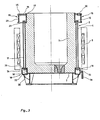
- French patents No. 2,366,079, No. 2,368,542, No. 2,368,543, No. 2,368,326 and No. 2,370,797 offer metallurgical bags of the type mentioned above -above. More particularly, French Patent No. 2,370,797 describes a metallurgical ladle, a schematic vertical section of which is shown in the appended figure.
- the pocket of the prior type is lined with a refractory lining 1.
- the tie rods 4 are held in place between two annular flanges, respectively upper 5 and lower 5 ', which are rigidly connected to a ferrule 6 and to the bottom 7 of the pocket.
- the ferrule 6 serves as a hoop at the upper end of the pocket and has two crowns, respectively upper 8 and lower 9, the lower ring 9 serving to support the pocket during its installation in an induction heating tank.
- the tie rods 4 are connected to the flanges 5 and 5 ′ by connection means 10 and have an axial internal conduit 11 which is connected to the zone 12 delimited by the crowns 8 and 9 via the connecting means 10 and a sealed extension 13.
- the cooling fluid is introduced at the lower end of the tie rods 4, rises in the conduit 11 and escapes into the zone 12.
- thermoelectric couples were implanted in different parts A (upper flange), B (bottom), C (ferrule), D (lower flange) and E (pulling) from the pocket, indicated on the figure 1.
- the attached figure 2 represents the results of this experiment.
- the highest temperature of the bag (450 ° C.) is noted on the upper flange 5 although the latter is located outside the heating zone.
- the temperature reached by the lower flange 5 ′ and the ferrule 6 is significantly lower (350 ° C).
- the temperature of the bottom 7 and of the tie rods 4 remains low (150 ° C.), which confirms the efficiency of the internal cooling described above.
- the object of the present invention is precisely to propose a metallurgical ladle, the solid metal parts of which do not overheat during high-power heating treatments and which at the same time has " good mechanical strength.
- the subject of the invention is a metallurgical ladle for the inductive treatment of metals, internally lined with a refractory lining and whose enclosure, of generally tubular shape, is constituted, in the heating zone, by metal tie rods longitudinal, electrically insulated from each other and protruding longitudinally above and below the heating zone, the tie rods being held in place by tightening at the upper part and at the lower part of the enclosure.
- the upper part of the enclosure is constituted by a box of generally annular shape and the tie rods are held in place at the upper part of the enclosure by connecting means, electrically insulating, between the upper ends of the tie rods and the bottom of the box.
- the lower part of the enclosure also consists of a box of generally annular shape which bears on the bottom of the pocket.
- the tie rods are also held in place at the lower part of the enclosure by electrically insulating connection means between the lower ends of the tie rods and the ceiling of the lower box.
- the connecting means consist of threaded connecting pieces at one of their ends and passing through openings in the bottom of the upper box and possibly in the ceiling of the lower box .
- the threaded ends of these parts are screwed into threads formed in the corresponding ends of the tie rods.
- each of the assembly parts consists of a threaded rod at its two ends. One of these ends is intended to be screwed into the thread of the corresponding tie rod and the other is intended to be screwed into a flange nut.
- each of the assembly pieces consists of a rod, one of the ends of which ends in a base and the other of which is threaded.
- the threaded end is intended to be screwed into the thread of the corresponding tie rod while the base is clamped against the internal face of the bottom of the upper box and possibly against the internal face of the ceiling of the lower box.
- each of the tie rods has an internal conduit, to allow the circulation of a cooling fluid.
- This duct communicates tightly with the interior of the box.
- the lower box is connected to a cooling fluid supply source and the upper box has an opening for the outlet of the fluid outside of the pocket.
- a downward circulation of the cooling fluid can be achieved by connecting the upper box to a source of fluid supply and by making an outlet opening for the fluid in the lower box.
- the device according to the invention has the advantage, compared to the bag of the prior type described above, that the upper and lower boxes are likely to be cooled quickly.
- the drawbacks due to the excessive heating of the flanges of the pocket of the previous type are avoided.
- the upper and lower boxes of the pocket according to the invention fulfill the function of holding in place and tightening the tie rods thanks to the special provisions of the connecting means between the tie rods and the boxes. Furthermore, the assembly and disassembly of the tie rods is easily carried out, as will be seen below.
- the pocket is lined internally with a refractory lining 1.
- the enclosure 2 of the pocket is formed in the inductive heating zone, that is to say in the part of the middle, by a large number of metallic tie rods 4.
- These tie rods 4 are made of non-magnetic material, for example non-magnetic stainless steel, so as not to channel the incident magnetic field lines to the detriment of the load to be treated.
- the tie rods 4 are distributed regularly around the refractory lining 1. The spaces formed between two consecutive tie rods 4 are occupied by seals 14 made of refractory material.
- the enclosure has an upper box 15 at its upper part and a lower box 16 at its lower part.
- Each of these boxes 15 and 16 is made up respectively of a ferrule 17 and 18 enveloping the refractory lining 1, of a ceiling 19 and 20, of a bottom 21 and 22 and of a wall 23 and 24.
- These various elements respectively define an interior space 25 and 26 of generally annular shape.
- the tie rods 4 are held in place by tightening between the upper box 15 and the lower box 16 by means of assembly 10.
- the upper box 15 has lateral pins 27 for the usual handling operations.
- the upper box 15 has, in addition to the function of tightening and maintaining the refractory lining 1, that of supporting, thanks to its bottom 21, the pocket during the installation of the latter in the induction heating tank.
- the boxes 15 and 16 preferably have openings 28 called “manholes" in their walls 23 and 24 to allow access to the assembly means 10. When the bag is put into service, the holes 28 men are blocked.
- a supply duct 29 supplies the lower box 16 with pressurized cooling fluid which generally is air.
- This fluid rises in the internal conduits I1 of the tie rods 4 and spreads inside 25 of the upper box 15. Then, the fluid escapes outside the pocket through the opening 30 provided for this purpose in the box. higher 15.
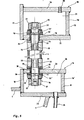
- the tie rods 4 are held by clamping between the bottom 21 of the upper box 15 and the ceiling 20 of the lower box 16 by means of the assembly means 10.
- Each of the tie rods 4 consists of 'a tubular rod 31, the ends 32 of which are internally threaded and bear on the external face of the bottom 21 of the upper box 15 and on the external face of the ceiling 20 of the lower box 16.
- These supports are provided by means of washers support 33 and flat annular seals 34.
- the assembly means 10 consist of a stud, the threaded rod 35 of which passes through an opening 36 provided for this purpose in the bottom 21 of the upper box 15 and in the ceiling 20 of the lower box 16.
- the assembly means 10 can be either a single piece stud, that is to say a rod ending at one of its ends by a thread and at the other by a base secured to the rod 35, either by a stud consisting of two parts separable from one another.
- the one-piece stud is more convenient for the assembly and disassembly of the tie rods 4. On the other hand, it is less easy to machine. In any case, the stud must have an internal conduit, so as to allow the passage of the cooling fluid.
- the assembly means 10 consist of two separable parts.
- the tubular rod 35 is threaded at its two ends. One of these ends is screwed into the thread 32 of the tie rod 4, and the other is engaged in a nut with base 37 by screwing, which allows the tightening of the tie rod 4 between the bottom 21 and the ceiling 20 of the boxes 15 and 16.
- the tightening of the nuts 37 is ensured against the internal face of the bottom 21 and the internal face of the ceiling 20 by l 'intermediate support washers 33' and flat annular seals 34 'identical to the support washers 33 and flat annular seals 34 described above.
- the openings 36 formed for the passage of the assembly means 10 in the bottom 21 of the upper box 15 and in the ceiling 20 of the lower box 16 have a diameter slightly greater than that of the threaded rods 35 which pass through them, so as to be able to place an annular seal 38 of the "cannon" type.
- Joints 33, 34, 33 ', 34' and 38 are above all good electrical and thermal insulators. They must also exhibit good resistance to temperature which can, where they are plastered, reach several hundred ° C., and good resistance to compression due to the inevitable expansions of the metallic structure during the commissioning of the pocket. Given all these requirements, the applicant recommends the use of a material sold under the name of "Syndanio", which is composed of a mixture of mineral stones and asbestos previously ground.
- the tie rods 4 and the corresponding studs 35 respectively have internal conduits II and 39 communicating with each other, so as to constitute passages for the cooling fluid between the interior 26 of the lower box 16 and the interior 25 of the upper box 15.
- the cooling fluid coming from a power source enters via line 29 in the lower box 16. It then circulates in the lower box 16, the tie rods 4 and the upper box 15 (via the conduits 11 and 39), cools them, then escapes outside the pocket through the opening 30 made in the upper box 15.
- the circulation of the cooling fluid is ascending, but it is also possible to produce a descending circulation.
- the upper box 15 is connected to a fluid supply source and the lower box 16 has an opening for letting the fluid exit outside the pocket.
- the invention has this additional advantage that the operation of replacing defective or used tie rods 4 is easy. Indeed, the assembly or disassembly of the enclosure 2 can be carried out at the level of the manholes 28 and 28 ′ without disassembling the boxes 15 and 16. During this operation, it is also possible to precisely adjust, tightening the tie rods 4 between the upper 15 and lower 16 boxes.
- the present invention cannot be limited to the particular embodiments described.
- the particular technology of the tie rods described with reference to FIG. 5 can be replaced by any other technology, the main thing being that the means of assembly of each of the tie rods with the upper box and, possibly, the lower box, are electrically insulating and keep the tie rods in place.
- cooling fluid air
- another gas for example water
Landscapes
- Physics & Mathematics (AREA)
- Electromagnetism (AREA)
- Engineering & Computer Science (AREA)
- Mechanical Engineering (AREA)
- Furnace Details (AREA)
Applications Claiming Priority (2)
| Application Number | Priority Date | Filing Date | Title |
|---|---|---|---|
| FR8024847A FR2494609B1 (fr) | 1980-11-21 | 1980-11-21 | Poche metallurgique pour le traitement inductif des metaux |
| FR8024847 | 1980-11-21 |
Publications (1)
| Publication Number | Publication Date |
|---|---|
| EP0053070A1 true EP0053070A1 (de) | 1982-06-02 |
Family
ID=9248265
Family Applications (1)
| Application Number | Title | Priority Date | Filing Date |
|---|---|---|---|
| EP81401821A Ceased EP0053070A1 (de) | 1980-11-21 | 1981-11-19 | Metallurgische Pfanne zum induktiven Behandeln von Metallen |
Country Status (8)
| Country | Link |
|---|---|
| US (1) | US4411412A (de) |
| EP (1) | EP0053070A1 (de) |
| JP (1) | JPS57115967A (de) |
| BR (1) | BR8107584A (de) |
| CA (1) | CA1179500A (de) |
| ES (1) | ES8300543A1 (de) |
| FR (1) | FR2494609B1 (de) |
| ZA (1) | ZA818005B (de) |
Cited By (12)
| Publication number | Priority date | Publication date | Assignee | Title |
|---|---|---|---|---|
| EP0144559A1 (de) * | 1983-09-09 | 1985-06-19 | Nippon Steel Corporation | Anlage zum Induktionserwärmen von geschmolzenem Metall |
| GB2161591A (en) * | 1984-07-14 | 1986-01-15 | Ipw Limited | Coreless induction furnace |
| DE4035552A1 (de) * | 1989-11-09 | 1991-05-16 | Fuji Electric Co Ltd | Vorrichtung zum erhitzen von geschmolzenem metall in einer giesspfanne |
| EP0439900A3 (en) * | 1990-01-31 | 1993-03-03 | Inductotherm Corp. | Induction heating apparatus and method |
| US5192488A (en) * | 1989-11-09 | 1993-03-09 | Fuji Electric Co., Ltd. | Apparatus for heating molten in a ladle |
| EP0576351A1 (de) * | 1992-06-24 | 1993-12-29 | Société CELES | Schutz und Kühlvorrichtung für die Pole eines elektromagnetischen Induktors |
| EP0612201A2 (de) | 1993-02-19 | 1994-08-24 | Inductotherm Corp. | Verbesserte Heizvorrichtung für Induktionsgefäss und Vakuumöfen |
| US5416794A (en) * | 1990-01-31 | 1995-05-16 | Inductotherm Corp. | Induction furnace havng a modular induction coil assembly |
| DE4410547A1 (de) * | 1994-03-26 | 1995-10-05 | Loewe Opta Gmbh | Verfahren zur Erstellung einer elektronischen Programmzeitschrift und Schaltung hierfür |
| CN104827018A (zh) * | 2015-04-02 | 2015-08-12 | 武汉西赛冶金工程有限责任公司 | 中间罐电磁定点靶区加热结构 |
| CN111957944A (zh) * | 2020-08-21 | 2020-11-20 | 佛山市南海创利有色金属制品有限公司 | 一种铝液运输保温装置 |
| WO2021036488A1 (zh) * | 2019-08-28 | 2021-03-04 | 南京星合精密智能制造研究院有限公司 | 一种低熔点合金异形芯模加工装置 |
Families Citing this family (5)
| Publication number | Priority date | Publication date | Assignee | Title |
|---|---|---|---|---|
| US5257281A (en) * | 1990-01-31 | 1993-10-26 | Inductotherm Corp. | Induction heating apparatus and method |
| US5550353A (en) * | 1990-01-31 | 1996-08-27 | Inductotherm Corp. | Induction heating coil assembly for prevent of circulating current in induction heating lines for continuous-cast products |
| US9004151B2 (en) * | 2012-09-27 | 2015-04-14 | Apple Inc. | Temperature regulated melt crucible for cold chamber die casting |
| US20150108325A1 (en) * | 2013-10-23 | 2015-04-23 | Keith Ryan | Method and apparatus for electrically-heated refractory moulds and mandrels |
| US20170048933A1 (en) * | 2014-10-24 | 2017-02-16 | Mario Metodiev | Air-cooled induction heating device |
Citations (3)
| Publication number | Priority date | Publication date | Assignee | Title |
|---|---|---|---|---|
| FR2225707A1 (de) * | 1973-04-11 | 1974-11-08 | Bbc Brown Boveri & Cie | |
| FR2368543A1 (fr) * | 1976-10-22 | 1978-05-19 | Siderurgie Fse Inst Rech | Perfectionnements aux poches metallurgiques a enceinte metallique fragmentee |
| FR2370797A1 (fr) * | 1976-11-16 | 1978-06-09 | Siderurgie Fse Inst Rech | Poche metallurgique pour traitements inductifs sous atmosphere controlee |
Family Cites Families (3)
| Publication number | Priority date | Publication date | Assignee | Title |
|---|---|---|---|---|
| US1823873A (en) * | 1930-01-23 | 1931-09-22 | Westinghouse Electric & Mfg Co | Induction furnace |
| SE432150B (sv) * | 1976-10-04 | 1984-03-19 | Siderurgie Fse Inst Rech | Apparat for metallurgisk induktionsbehandling av metaller och metalliska eller andra legeringar |
| FR2366079A1 (fr) * | 1976-10-04 | 1978-04-28 | Siderurgie Fse Inst Rech | Poche metallurgique a enceinte metallique fragmentee |
-
1980
- 1980-11-21 FR FR8024847A patent/FR2494609B1/fr not_active Expired
-
1981
- 1981-11-18 ZA ZA818005A patent/ZA818005B/xx unknown
- 1981-11-19 EP EP81401821A patent/EP0053070A1/de not_active Ceased
- 1981-11-20 BR BR8107584A patent/BR8107584A/pt unknown
- 1981-11-20 JP JP56186783A patent/JPS57115967A/ja active Pending
- 1981-11-20 ES ES507341A patent/ES8300543A1/es not_active Expired
- 1981-11-20 CA CA000390626A patent/CA1179500A/fr not_active Expired
- 1981-11-23 US US06/323,907 patent/US4411412A/en not_active Expired - Fee Related
Patent Citations (3)
| Publication number | Priority date | Publication date | Assignee | Title |
|---|---|---|---|---|
| FR2225707A1 (de) * | 1973-04-11 | 1974-11-08 | Bbc Brown Boveri & Cie | |
| FR2368543A1 (fr) * | 1976-10-22 | 1978-05-19 | Siderurgie Fse Inst Rech | Perfectionnements aux poches metallurgiques a enceinte metallique fragmentee |
| FR2370797A1 (fr) * | 1976-11-16 | 1978-06-09 | Siderurgie Fse Inst Rech | Poche metallurgique pour traitements inductifs sous atmosphere controlee |
Cited By (20)
| Publication number | Priority date | Publication date | Assignee | Title |
|---|---|---|---|---|
| EP0144559A1 (de) * | 1983-09-09 | 1985-06-19 | Nippon Steel Corporation | Anlage zum Induktionserwärmen von geschmolzenem Metall |
| GB2161591A (en) * | 1984-07-14 | 1986-01-15 | Ipw Limited | Coreless induction furnace |
| DE4035552A1 (de) * | 1989-11-09 | 1991-05-16 | Fuji Electric Co Ltd | Vorrichtung zum erhitzen von geschmolzenem metall in einer giesspfanne |
| GB2238496A (en) * | 1989-11-09 | 1991-06-05 | Fuji Electric Co Ltd | Ladle with apparatus for heating molten metal |
| US5164148A (en) * | 1989-11-09 | 1992-11-17 | Fuji Electric Corporation, Ltd. | Apparatus for heating molten metal in a ladle |
| US5192488A (en) * | 1989-11-09 | 1993-03-09 | Fuji Electric Co., Ltd. | Apparatus for heating molten in a ladle |
| GB2238496B (en) * | 1989-11-09 | 1994-07-06 | Fuji Electric Co Ltd | Apparatus for heating molten metal in a ladle |
| US5416794A (en) * | 1990-01-31 | 1995-05-16 | Inductotherm Corp. | Induction furnace havng a modular induction coil assembly |
| EP0439900A3 (en) * | 1990-01-31 | 1993-03-03 | Inductotherm Corp. | Induction heating apparatus and method |
| US5425048A (en) * | 1990-01-31 | 1995-06-13 | Inductotherm Corp. | Heating apparatus for induction ladle and vacuum furnaces |
| US5485483A (en) * | 1992-06-24 | 1996-01-16 | Celes | Device for protecting and cooling the poles of an electromagnetic inductor |
| FR2693073A1 (fr) * | 1992-06-24 | 1993-12-31 | Celes | Dispositif de protection et de refroidissement des pôles d'un inducteur électro-magnétique. |
| EP0576351A1 (de) * | 1992-06-24 | 1993-12-29 | Société CELES | Schutz und Kühlvorrichtung für die Pole eines elektromagnetischen Induktors |
| EP0612201A3 (en) * | 1993-02-19 | 1994-09-21 | Inductotherm Corp | Improved heating apparatus for induction ladle and vacuum furnaces. |
| EP0612201A2 (de) | 1993-02-19 | 1994-08-24 | Inductotherm Corp. | Verbesserte Heizvorrichtung für Induktionsgefäss und Vakuumöfen |
| DE4410547A1 (de) * | 1994-03-26 | 1995-10-05 | Loewe Opta Gmbh | Verfahren zur Erstellung einer elektronischen Programmzeitschrift und Schaltung hierfür |
| DE4410547C2 (de) * | 1994-03-26 | 1999-03-18 | Loewe Opta Gmbh | Verfahren zur Erstellung einer elektronischen Programmzeitschrift und Schaltung hierfür |
| CN104827018A (zh) * | 2015-04-02 | 2015-08-12 | 武汉西赛冶金工程有限责任公司 | 中间罐电磁定点靶区加热结构 |
| WO2021036488A1 (zh) * | 2019-08-28 | 2021-03-04 | 南京星合精密智能制造研究院有限公司 | 一种低熔点合金异形芯模加工装置 |
| CN111957944A (zh) * | 2020-08-21 | 2020-11-20 | 佛山市南海创利有色金属制品有限公司 | 一种铝液运输保温装置 |
Also Published As
| Publication number | Publication date |
|---|---|
| ZA818005B (en) | 1982-10-27 |
| FR2494609A1 (fr) | 1982-05-28 |
| BR8107584A (pt) | 1982-08-17 |
| ES507341A0 (es) | 1982-11-01 |
| US4411412A (en) | 1983-10-25 |
| FR2494609B1 (fr) | 1985-12-27 |
| JPS57115967A (en) | 1982-07-19 |
| ES8300543A1 (es) | 1982-11-01 |
| CA1179500A (fr) | 1984-12-18 |
Similar Documents
| Publication | Publication Date | Title |
|---|---|---|
| EP0053070A1 (de) | Metallurgische Pfanne zum induktiven Behandeln von Metallen | |
| EP0836751B1 (de) | Thermoelektrischer generator | |
| EP0056915B1 (de) | Anlage zum direkten Induktionsschmelzen in einem gekühlten Tiegel mit zusätzlicher elektromagnetischer Halterung des Schmelzgutes | |
| EP0235465B1 (de) | Elektrische Verbindungsvorrichtung zum Anbringen in die Wand eines metallurgischen Gleichstromofens | |
| EP0477066A1 (de) | Verfahren zum Austauschen eines Rohres eines Wärmetauschers und Anwendung dieses Verfahrens | |
| CA1091736A (fr) | Poches metallurgiques pour les traitements inductifs des metaux | |
| EP0178981B1 (de) | Elektrodenanordnung für Metallschmelzbad | |
| EP0169100B1 (de) | Wandelektrode eines metallurgischen Gefässes in Kontakt mit geschmolzenem Metall | |
| CA1086806A (fr) | Poche metallurgique pour les traitements inductifs des metaux | |
| CA1263679A (fr) | Electrode de paroi pour four metallurgique electrique a courant continu | |
| EP1753695B1 (de) | Siliziumverfeinerungsanlage | |
| EP0344245A1 (de) | Elektrischer tauchsieder | |
| FR2669470A1 (fr) | Procede de refroidissement d'une amenee de courant pour appareillage electrique a tres basse temperature et dispositif pour sa mise en óoeuvre. | |
| CH405536A (fr) | Procédé pour souder bout à bout deux tubes depuis l'intérieur et torche de soudure à l'arc électrique pour la mise en oeuvre de ce procédé | |
| FR2658277A1 (fr) | Recipient metallurgique equipe d'au moins une electrode traversant sa paroi. | |
| EP0161949B1 (de) | Mit flüssigem Metall gekühlter Kernreaktor | |
| FR2715941A1 (fr) | Four à courant continu de fusion de métal. | |
| CH504759A (fr) | Pot de stockage et de manutention d'un assemblage combustible nucléaire | |
| WO2012127152A1 (fr) | Creuset de four a induction | |
| EP0090743B1 (de) | Schutzvorrichtung gegen Wärme und Radiation für einen in einem Kernreaktorbehälter eingetauchten Wärmeübertrager | |
| BE567336A (de) | ||
| FR2593002A1 (fr) | Pompe electromagnetique pour liquide conducteur a refoulement par repulsion magnetique. | |
| FR2514981A1 (fr) | Dispositif de porte-electrode pour electrodes auto-durcissantes | |
| EP0095428A1 (de) | Gaskühleinrichtung für den Druckbehälterdeckel eines Kernreaktors | |
| BE559018A (de) |
Legal Events
| Date | Code | Title | Description |
|---|---|---|---|
| PUAI | Public reference made under article 153(3) epc to a published international application that has entered the european phase |
Free format text: ORIGINAL CODE: 0009012 |
|
| AK | Designated contracting states |
Designated state(s): AT BE DE FR GB IT LU NL SE |
|
| 17P | Request for examination filed |
Effective date: 19821125 |
|
| STAA | Information on the status of an ep patent application or granted ep patent |
Free format text: STATUS: THE APPLICATION HAS BEEN REFUSED |
|
| 18R | Application refused |
Effective date: 19870806 |
|
| RIN1 | Information on inventor provided before grant (corrected) |
Inventor name: LECHEVALLIER, CHRISTIAN |