EP0053103B1 - Schaltung zum Erfassen und Melden von Fehlern und von Betriebsunregelmässigkeiten einer Batterieladeeinrichtung - Google Patents
Schaltung zum Erfassen und Melden von Fehlern und von Betriebsunregelmässigkeiten einer Batterieladeeinrichtung Download PDFInfo
- Publication number
- EP0053103B1 EP0053103B1 EP81830211A EP81830211A EP0053103B1 EP 0053103 B1 EP0053103 B1 EP 0053103B1 EP 81830211 A EP81830211 A EP 81830211A EP 81830211 A EP81830211 A EP 81830211A EP 0053103 B1 EP0053103 B1 EP 0053103B1
- Authority
- EP
- European Patent Office
- Prior art keywords
- circuit
- voltage
- signal
- alternator
- output
- Prior art date
- Legal status (The legal status is an assumption and is not a legal conclusion. Google has not performed a legal analysis and makes no representation as to the accuracy of the status listed.)
- Expired
Links
Images


Classifications
-
- H—ELECTRICITY
- H02—GENERATION; CONVERSION OR DISTRIBUTION OF ELECTRIC POWER
- H02J—ELECTRIC POWER NETWORKS; CIRCUIT ARRANGEMENTS OR SYSTEMS FOR SUPPLYING OR DISTRIBUTING ELECTRIC POWER; SYSTEMS FOR STORING ELECTRIC ENERGY
- H02J7/00—Circuit arrangements for charging or discharging batteries or for supplying loads from batteries
- H02J7/14—Circuit arrangements for charging or discharging batteries or for supplying loads from batteries for charging batteries from dynamo-electric generators driven at varying speed, e.g. on vehicle
- H02J7/16—Regulation of the charging current or voltage by variation of field
-
- H—ELECTRICITY
- H02—GENERATION; CONVERSION OR DISTRIBUTION OF ELECTRIC POWER
- H02J—ELECTRIC POWER NETWORKS; CIRCUIT ARRANGEMENTS OR SYSTEMS FOR SUPPLYING OR DISTRIBUTING ELECTRIC POWER; SYSTEMS FOR STORING ELECTRIC ENERGY
- H02J7/00—Circuit arrangements for charging or discharging batteries or for supplying loads from batteries
- H02J7/60—Circuit arrangements for charging or discharging batteries or for supplying loads from batteries including safety or protection arrangements
- H02J7/64—Circuit arrangements for charging or discharging batteries or for supplying loads from batteries including safety or protection arrangements against overvoltage
-
- H—ELECTRICITY
- H02—GENERATION; CONVERSION OR DISTRIBUTION OF ELECTRIC POWER
- H02J—ELECTRIC POWER NETWORKS; CIRCUIT ARRANGEMENTS OR SYSTEMS FOR SUPPLYING OR DISTRIBUTING ELECTRIC POWER; SYSTEMS FOR STORING ELECTRIC ENERGY
- H02J7/00—Circuit arrangements for charging or discharging batteries or for supplying loads from batteries
- H02J7/80—Circuit arrangements for charging or discharging batteries or for supplying loads from batteries including monitoring or indicating arrangements
-
- Y—GENERAL TAGGING OF NEW TECHNOLOGICAL DEVELOPMENTS; GENERAL TAGGING OF CROSS-SECTIONAL TECHNOLOGIES SPANNING OVER SEVERAL SECTIONS OF THE IPC; TECHNICAL SUBJECTS COVERED BY FORMER USPC CROSS-REFERENCE ART COLLECTIONS [XRACs] AND DIGESTS
- Y10—TECHNICAL SUBJECTS COVERED BY FORMER USPC
- Y10S—TECHNICAL SUBJECTS COVERED BY FORMER USPC CROSS-REFERENCE ART COLLECTIONS [XRACs] AND DIGESTS
- Y10S320/00—Electricity: battery or capacitor charging or discharging
- Y10S320/13—Fault detection
Definitions
- the present invention relates to circuits for detecting and indicating faults and operating anomalies in a system for charging electric accumulators, particularly to circuits of the kind according to the first part of appended Claim 1.
- a fault detecting and indicating circuit of the above specified kind is disclosed in EP-A1-0 013 496.
- a processor circuit provides an output test signal substantially proportional to the signal present at the virtual star point of the armature windings.
- a circuit arrangement in which a processor circuit is connected to the real star point of the alternator windings is disclosed in FR-A-2 060 698.
- the processor circuit is a low-pass filter which provides an output signal proportional to the mean value of the signal present in operation at said star point.
- the voltage regulator is arranged so that the charging voltage varies as a function of the temperature in accordance with a predetermined law.
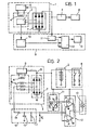
- FIG. 1 there is illustrated a conventional type of system, generally indicated 1, for recharging, for example, a battery 2 carried by a motor vehicle.
- the recharging system 1 includes a three-phase alternator 3 comprising a field winding 4 and a three-phase armature winding 5.
- the field winding 4 is connected to a voltage regulator. circuit 6, whilst the three-phase winding 5 is connected to a double half-wave rectifier circuit 7 of the Graetz bridge type.
- the output of the rectifier circuit 7 is connected to the input of the voltage regulator circuit 6 and the battery 2.
- the voltages generated in the three-phase windings 5 of the alternator 3 are rectified by the rectifier circuit 7 which supplies a recharging voltage to the battery 2.
- the voltage regulator circuit 6, as is known, modulates the current flowing in the field winding 4 in such a way as to maintain constant the recharging voltage (also called the regulation voltage) when variations occur in the speed of rotation of the alternator and the mains current.
- a circuit for detecting and indicating faults and operating anomalies which may occur in operation of the recharging system 1 described above is generally indicated 9.
- the detector and indicator circuit 9 includes a signal processor circuit 10 connected to the three-phase winding 5 of the alternator 3 in a manner which will be described below.
- a reference signal generator, generally indicated at 11, is connected to the output of the rectifier circuit 7.
- a comparison circuit 12 is connected to the signal processor circuit 10 and the reference signal generator 11.
- An alarm indicator device 13 for example of the visual type, is connected to the output of this comparison circuit.
- the signal processor circuit 10 can be constituted, in general, by a low-pass filter, and serves to integrate the signal present at the real or virtual star point of the three-phase winding 5 of the alternator 3. It may be constituted, for example, by a passive integrator of the RC type, as illustrated in Figures 2 and 3.
- Figure 2 shows a possible embodiment of the signal processor circuit 10 for a case in which the windings (the phases) of the three-phase winding 5 of the alternator 3 are star-connected.
- the integrator circuit 10 comprises a resistor 14 having one terminal connected to the star point of the three-phase winding 5 and the other terminal connected to an earthed capacitor 15.
- the signal processor circuit 10 can be formed in the manner illustrated in Figure 3.
- the signal processor circuit 10 is constituted by a group of three star-connected resistors 16 connected between the phases of the alternator 3.
- the common terminal S of the three resistors 16 represents the "virtual" star point of the three-phase winding 5.
- the potential of the terminal S with respect to earth corresponds to the potential which would occur at the star point of a star-connected three-phase winding equivalent to the delta-connected three-phase winding illustrated in Figure 3.
- the capacitor 15 is connected between the terminal S and earth.
- the signal processor circuit 10 can be constituted by any other passive or active integrator circuit of conventional type.
- the signal processor circuit 10 integrates the alternating signal present at the real or virtual star point of the armature winding of the alternator and provides an output signal substantially proportional to the mean d.c. value of the signal at the star point. If the output of the rectifier circuit 7 is indicated B and the voltage between this terminal and earth (that is, the charging voltage for the battery 2) is V B then, given the symmetry of the system and the absence of faults, there is present at the real or virtual star point of the alternator an alternating signal the mean d.c. value of which is equal to half the charging voltage V B . In the embodiment illustrated, therefore, the signal processor circuit 10 provides an output voltage V, substantially proportional to the mean d.c. value of the signal at the star point and, therefore, proportional to the battery charging voltage V B . In particular, in the examples of Figures 2 and 3 if the recharging system 1 is operating properly the voltage V i is equal to half the voltage V B .
- the proportionality factor between the voltage V i and the voltage V B can be varied by, for example, inserting a resistor 17 in parallel with the capacitor 15.
- the signal processor circuit 10 provides at its output a signal V i different from the voltage k.V B .
- the voltage V can, in general, rise or fall with respect to the value k.V B which it assumes in the absence of faults. If, for example, one of the diodes connected to the output terminal B in the rectifier circuit 7 is short-circuited the voltage V i increases. On the other hand, in the event of, for example, a short-circuit of one of the diodes connected to earth, the voltage V, falls.
- a comparison circuit 12 formed, for example, in the manner illustrated in Figure 2.
- This comparison circuit includes two comparator circuits 18, 19 each having a first input connected to the output of the signal processor circuit 10, and outputs which are connected together.
- the comparator circuits 18, 19 also have respective second inputs each connected to an output of the reference signal generator circuit 11.
- the latter circuit can be formed, for example, in the manner illustrated in Figure 2. In this example, it comprises two resistive voltage dividers connected in parallel between the output of the rectifier circuit 7 and earth. These two voltage dividers are so dimensioned that they provide at their outputs two voltages, V 1 and V 2 respectively, in accordance with the following relations:
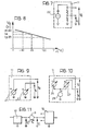
- the reference voltage level generator circuit 11 can be formed, alternatively, in the manner illustrated by way of example in Figure 3.
- the comparison circuit.12 can be constituted, for example, by a single integrated circuit (double comparator) of conventional type.
- the indicator lamp 13 may alternatively be connected between the output of the comparison circuit 12 and earth. In this case, it is necessary to connect a logic inverter circuit between the output of the comparison circuit 12 and the lamp 13 or, alternatively, it is necessary to utilise a comparison circuit formed in such a way that its output will be at the "low" level when V 1 ⁇ V i ⁇ V 2 and at a "high" level when V i ⁇ V i and when V i ⁇ V 2 .
- the outputs of the comparator circuits 18, 19, may be connected directly together as illustrated in Figure 2, or, alternatively, they can be connected to two separate inputs of a OR logic circuit (not shown) the output of which is connected to the lamp 13.
- the output of the comparison circuit 12 can be connected directly to the lamp 13 or through a commutator circuit C, for example, of the type illustrated in Figure 4.
- FIG 5 there is illustrated a variant in which the outputs of the comparator circuits 18, 19 are each connected to respective indicator lamps 13a, 13b.
- This arrangement makes it possible to discriminate between faults according to whether they are of the type which cause an increase in the voltage V i relative to the normal value, or the type which cause a fall in this voltage.
- the lamps 13a, 13b may be connected to the battery (as shown in Figure 5) or to earth, with the same considerations as discussed above with reference to a single indicator lamp being valid.
- commutator circuits of the type shown in Figure 4 may be connected between the outputs of the comparator circuits 18,19 and the lamps 13a, 13b.
- the reference voltage generator circuits illustrated in Figures 2 and 3 are operable to provide at their outputs reference voltages V 1 , V 2 proportional to the battery charging voltage V B set by the regulator circuit 6.
- the circuit 9 for detecting and indicating faults and operating anomalies of the recharging system 1 has a limitation for this reason. In fact, since even the voltage V ; is proportional to the voltage V B in normal operating conditions of the recharging system 1, the circuit 9 described with reference to Figures 2 and 3 is not able to indicate faults which cause a variation in the voltage V B relative to the set value determined by the regulator circuit 6.
- Figure 6 illustrates a circuit 11 operable to provide at its output two stabilised reference voltages V 1 , V 2 which are therefore independent of the voltage V B .
- the arrangement illustrated in Figure 6 makes use of a resistor 20 connected in series with a Zener diode 21 between the output of the rectifier circuit 7 and earth. Two resistive voltage dividers are connected in parallel with the Zener diode 21, which provide the reference voltages at their output.
- any other type of conventional circuit which can provide two different stabilised reference voltages can be adopted in place of the circuit illustrated in Figure 6.
- One possible variation may be constituted, for example, by the circuit illustrated in Figure 7.
- This variant envisages the use of a constant current generator 22 (of conventional type) which is connected to two resistors connected in the manner illustrated in Figure 7.
- a signal processor circuit 10 can be constituted, in general, by an integrating filter.
- the signal V, provided at the output can have a greater or lesser residual wave form (ripple).
- the residual alternating component present in the signal V has an amplitude greater than the value 2.AV, it is possible that the outputs of both the comparator circuits 18,19 will change state. This then causes the illumination of the indicator lamp (or both lamps).
- the circuit above described therefore allows the residual alternating component present in the signal V, to be used for the indication of some types of faults.
- the detecting and indicating circuit in the embodiments illustrated so far allows the detection and indication of the following faults:
- FIG. 9 shows a reference voltage generator circuit 11 employing two voltage generators 23, 24 operable to provide an output voltage V 1 and an output voltage V 2 respectively, having a coefficient of thermal variation equal to
- This arrangement ensures that, upon a variation in temperature, the width 2.AV of the band in which the voltage V, can vary without an alarm indication being given remains unaltered.
- Figure 10 illustrates a simple variant of the circuit illustrated in Figure 9.
- This arrangement comprises a reference level generator circuit 11 which is formed by a constant voltage generator 25 and two different voltage generators 26, 27 generating different voltages but having the same law of thermal variation as V,.
- FIG 11 illustrates an alternative variant to that shown in Figures 9 and 10, in which the reference voltages V 1 , V 2 vary as a function of temperature with the same law of voltage variation as the voltage V i ,.
- a conventional voltage generator G operable to generate a voltage V with a law of variation which is a function of the temperature and a value such that the voltage ( Figure 11) is unvarying upon variations in the temperature.
- the voltage V can therefore be compared with the stabilised reference voltages V io being the value assumed by V i in the absence of faults.
- Further variants may be developed easily by using current generators which vary as a function of temperature.
- the circuit according to the invention performs a comparison between a signal V i and two reference voltages (V i , V 2 ) which are respectively equal to V io - ⁇ V, and V io + ⁇ V.
- V i , V 2 reference voltages
- this embodiment comprises the provision of a signal processor circuit 10 formed in any of the ways described above, which has its output connected to a signal translator circuit 30.
- This circuit may be formed, for example, in the manner illustrated in Figure 13, and can include two voltage generators 31, 32 operable to generate a voltage AV.
- the negative terminal of the voltage generator 31 and the positive terminal of the voltage generator 32 are connected to the output of the integrator circuit 10. Therefore, the voltages V i - ⁇ V and V i + ⁇ V, as indicated in Figure 13, will be present at the output of the translator circuit 30.
- the outputs of the translator circuit 30 are connected to respective inputs of the comparator circuits 18, 19 of the comparison circuit 12.
- the output of this circuit 33 is connected to another input of the comparator circuits 18, 19.
- the output of the comparison circuit 12 passes from the "high” level to the "low” level when, because of a fault or an operating anomaly, the following relations occur:
- the indicator means may be constituted by a single lamp or two lamps, as described above with reference to Figures 4 and 5.
Landscapes
- Engineering & Computer Science (AREA)
- Power Engineering (AREA)
- Control Of Charge By Means Of Generators (AREA)
- Charge And Discharge Circuits For Batteries Or The Like (AREA)
- Remote Monitoring And Control Of Power-Distribution Networks (AREA)
- Control Of Eletrric Generators (AREA)
- Measurement Of Current Or Voltage (AREA)
- Selective Calling Equipment (AREA)
- Protection Of Generators And Motors (AREA)
- Protection Of Static Devices (AREA)
Claims (3)
Priority Applications (1)
| Application Number | Priority Date | Filing Date | Title |
|---|---|---|---|
| AT81830211T ATE17538T1 (de) | 1980-11-26 | 1981-10-28 | Schaltung zum erfassen und melden von fehlern und von betriebsunregelmaessigkeiten einer batterieladeeinrichtung. |
Applications Claiming Priority (2)
| Application Number | Priority Date | Filing Date | Title |
|---|---|---|---|
| IT6880480 | 1980-11-26 | ||
| IT68804/80A IT1130536B (it) | 1980-11-26 | 1980-11-26 | Circuito per la rivelazione e la segnalazione di guasti e di anomalie di funzionamento in un impianto di ricarica di accumulatori elettrici |
Publications (2)
| Publication Number | Publication Date |
|---|---|
| EP0053103A1 EP0053103A1 (de) | 1982-06-02 |
| EP0053103B1 true EP0053103B1 (de) | 1986-01-15 |
Family
ID=11310620
Family Applications (1)
| Application Number | Title | Priority Date | Filing Date |
|---|---|---|---|
| EP81830211A Expired EP0053103B1 (de) | 1980-11-26 | 1981-10-28 | Schaltung zum Erfassen und Melden von Fehlern und von Betriebsunregelmässigkeiten einer Batterieladeeinrichtung |
Country Status (7)
| Country | Link |
|---|---|
| US (1) | US4412169A (de) |
| EP (1) | EP0053103B1 (de) |
| JP (1) | JPS57119623A (de) |
| AT (1) | ATE17538T1 (de) |
| DE (1) | DE3173527D1 (de) |
| ES (1) | ES508008A0 (de) |
| IT (1) | IT1130536B (de) |
Families Citing this family (156)
| Publication number | Priority date | Publication date | Assignee | Title |
|---|---|---|---|---|
| JPS59148538A (ja) * | 1983-02-10 | 1984-08-25 | 株式会社日立製作所 | 充電発電機用電圧調整装置 |
| JPS6022429A (ja) * | 1983-07-18 | 1985-02-04 | 株式会社日立製作所 | 充電発電機用電圧調整装置 |
| JPS6087635A (ja) * | 1983-10-18 | 1985-05-17 | 三菱電機株式会社 | 直流発電機の出力端子の開放故障検出装置 |
| FR2649797B1 (fr) * | 1989-07-11 | 1991-10-31 | Valeo Equip Electr Moteur | Circuit de detection du signal phase alternateur polyphase de controle d'un regulateur de charge de batterie de vehicule automobile et son utilisation |
| EP0577994B1 (de) * | 1992-06-25 | 1997-05-21 | Motorola, Inc. | Wechselstromgeneratorspannungsregler mit Umdrehungsfeststeller und System zum Laden einer Batterie durch diesen Wechselstromgenerator |
| DE4226311A1 (de) * | 1992-08-08 | 1994-02-10 | Audi Ag | Drehstromgenerator |
| AT399235B (de) * | 1992-12-24 | 1995-04-25 | Vaillant Gmbh | Verfahren zur funktionskontrolle eines temperaturfühlers |
| US7246015B2 (en) | 1996-07-29 | 2007-07-17 | Midtronics, Inc. | Alternator tester |
| US6445158B1 (en) | 1996-07-29 | 2002-09-03 | Midtronics, Inc. | Vehicle electrical system tester with encoded output |
| US6885195B2 (en) | 1996-07-29 | 2005-04-26 | Midtronics, Inc. | Method and apparatus for auditing a battery test |
| US6633165B2 (en) | 1997-11-03 | 2003-10-14 | Midtronics, Inc. | In-vehicle battery monitor |
| US6566883B1 (en) | 1999-11-01 | 2003-05-20 | Midtronics, Inc. | Electronic battery tester |
| US6914413B2 (en) | 1996-07-29 | 2005-07-05 | Midtronics, Inc. | Alternator tester with encoded output |
| US6331762B1 (en) | 1997-11-03 | 2001-12-18 | Midtronics, Inc. | Energy management system for automotive vehicle |
| US6329793B1 (en) | 1996-07-29 | 2001-12-11 | Midtronics, Inc. | Method and apparatus for charging a battery |
| US6351102B1 (en) | 1999-04-16 | 2002-02-26 | Midtronics, Inc. | Automotive battery charging system tester |
| US6850037B2 (en) | 1997-11-03 | 2005-02-01 | Midtronics, Inc. | In-vehicle battery monitor |
| US7706991B2 (en) | 1996-07-29 | 2010-04-27 | Midtronics, Inc. | Alternator tester |
| US8872517B2 (en) | 1996-07-29 | 2014-10-28 | Midtronics, Inc. | Electronic battery tester with battery age input |
| US6051976A (en) * | 1996-07-29 | 2000-04-18 | Midtronics, Inc. | Method and apparatus for auditing a battery test |
| US6081098A (en) * | 1997-11-03 | 2000-06-27 | Midtronics, Inc. | Method and apparatus for charging a battery |
| US7003410B2 (en) | 1996-07-29 | 2006-02-21 | Midtronics, Inc. | Electronic battery tester with relative test output |
| US8198900B2 (en) | 1996-07-29 | 2012-06-12 | Midtronics, Inc. | Automotive battery charging system tester |
| US6332113B1 (en) | 1996-10-07 | 2001-12-18 | Midtronics, Inc. | Electronic battery tester |
| US5914605A (en) | 1997-01-13 | 1999-06-22 | Midtronics, Inc. | Electronic battery tester |
| FR2769771B1 (fr) * | 1997-10-15 | 1999-12-31 | Valeo Equip Electr Moteur | Dispositif pour le redressement synchrone d'un alternateur |
| US6586941B2 (en) | 2000-03-27 | 2003-07-01 | Midtronics, Inc. | Battery tester with databus |
| US7705602B2 (en) | 1997-11-03 | 2010-04-27 | Midtronics, Inc. | Automotive vehicle electrical system diagnostic device |
| US8958998B2 (en) | 1997-11-03 | 2015-02-17 | Midtronics, Inc. | Electronic battery tester with network communication |
| US7126341B2 (en) | 1997-11-03 | 2006-10-24 | Midtronics, Inc. | Automotive vehicle electrical system diagnostic device |
| US7774151B2 (en) | 1997-11-03 | 2010-08-10 | Midtronics, Inc. | Wireless battery monitor |
| US6871151B2 (en) | 1997-11-03 | 2005-03-22 | Midtronics, Inc. | Electronic battery tester with network communication |
| US7688074B2 (en) | 1997-11-03 | 2010-03-30 | Midtronics, Inc. | Energy management system for automotive vehicle |
| US6172505B1 (en) | 1998-04-27 | 2001-01-09 | Midtronics, Inc. | Electronic battery tester |
| WO2000007256A1 (en) | 1998-07-27 | 2000-02-10 | Gnb Technologies | Apparatus and method for carrying out diagnostic tests on batteries and for rapidly charging batteries |
| US6002238A (en) | 1998-09-11 | 1999-12-14 | Champlin; Keith S. | Method and apparatus for measuring complex impedance of cells and batteries |
| US6262563B1 (en) | 1998-09-11 | 2001-07-17 | Keith S. Champlin | Method and apparatus for measuring complex admittance of cells and batteries |
| US6037777A (en) | 1998-09-11 | 2000-03-14 | Champlin; Keith S. | Method and apparatus for determining battery properties from complex impedance/admittance |
| US6294896B1 (en) | 1998-09-11 | 2001-09-25 | Keith S. Champlin | Method and apparatus for measuring complex self-immitance of a general electrical element |
| US7505856B2 (en) | 1999-04-08 | 2009-03-17 | Midtronics, Inc. | Battery test module |
| AU4333000A (en) | 1999-04-08 | 2000-11-14 | Midtronics, Inc. | Electronic battery tester |
| US7058525B2 (en) | 1999-04-08 | 2006-06-06 | Midtronics, Inc. | Battery test module |
| US6795782B2 (en) | 1999-04-08 | 2004-09-21 | Midtronics, Inc. | Battery test module |
| US7039533B2 (en) | 1999-04-08 | 2006-05-02 | Midtronics, Inc. | Battery test module |
| US6456045B1 (en) | 1999-04-16 | 2002-09-24 | Midtronics, Inc. | Integrated conductance and load test based electronic battery tester |
| US6359441B1 (en) | 1999-04-30 | 2002-03-19 | Midtronics, Inc. | Electronic battery tester |
| US6316914B1 (en) | 1999-05-05 | 2001-11-13 | Midtronics, Inc. | Testing parallel strings of storage batteries |
| US6441585B1 (en) | 1999-06-16 | 2002-08-27 | Midtronics, Inc. | Apparatus and method for testing rechargeable energy storage batteries |
| US6313607B1 (en) | 1999-09-01 | 2001-11-06 | Keith S. Champlin | Method and apparatus for evaluating stored charge in an electrochemical cell or battery |
| US6737831B2 (en) | 1999-09-01 | 2004-05-18 | Keith S. Champlin | Method and apparatus using a circuit model to evaluate cell/battery parameters |
| US6137269A (en) | 1999-09-01 | 2000-10-24 | Champlin; Keith S. | Method and apparatus for electronically evaluating the internal temperature of an electrochemical cell or battery |
| US6163156A (en) * | 1999-11-01 | 2000-12-19 | Midtronics, Inc. | Electrical connection for electronic battery tester |
| US6249124B1 (en) | 1999-11-01 | 2001-06-19 | Midtronics, Inc. | Electronic battery tester with internal battery |
| US6363303B1 (en) | 1999-11-01 | 2002-03-26 | Midtronics, Inc. | Alternator diagnostic system |
| US6466025B1 (en) | 2000-01-13 | 2002-10-15 | Midtronics, Inc. | Alternator tester |
| US6225808B1 (en) | 2000-02-25 | 2001-05-01 | Midtronics, Inc. | Test counter for electronic battery tester |
| US7598744B2 (en) | 2000-03-27 | 2009-10-06 | Midtronics, Inc. | Scan tool for electronic battery tester |
| US6759849B2 (en) | 2000-03-27 | 2004-07-06 | Kevin I. Bertness | Battery tester configured to receive a removable digital module |
| US7446536B2 (en) | 2000-03-27 | 2008-11-04 | Midtronics, Inc. | Scan tool for electronic battery tester |
| US7598743B2 (en) | 2000-03-27 | 2009-10-06 | Midtronics, Inc. | Battery maintenance device having databus connection |
| US8513949B2 (en) | 2000-03-27 | 2013-08-20 | Midtronics, Inc. | Electronic battery tester or charger with databus connection |
| US7398176B2 (en) | 2000-03-27 | 2008-07-08 | Midtronics, Inc. | Battery testers with secondary functionality |
| US6967484B2 (en) | 2000-03-27 | 2005-11-22 | Midtronics, Inc. | Electronic battery tester with automotive scan tool communication |
| US6304087B1 (en) | 2000-09-05 | 2001-10-16 | Midtronics, Inc. | Apparatus for calibrating electronic battery tester |
| US6906523B2 (en) | 2000-09-14 | 2005-06-14 | Midtronics, Inc. | Method and apparatus for testing cells and batteries embedded in series/parallel systems |
| US6417669B1 (en) | 2001-06-11 | 2002-07-09 | Keith S. Champlin | Suppressing interference in AC measurements of cells, batteries and other electrical elements |
| US6788025B2 (en) | 2001-06-22 | 2004-09-07 | Midtronics, Inc. | Battery charger with booster pack |
| US7015674B2 (en) | 2001-06-22 | 2006-03-21 | Midtronics, Inc. | Booster pack with storage capacitor |
| US7501795B2 (en) | 2001-06-22 | 2009-03-10 | Midtronics Inc. | Battery charger with booster pack |
| US7479763B2 (en) | 2001-06-22 | 2009-01-20 | Midtronics, Inc. | Apparatus and method for counteracting self discharge in a storage battery |
| US6469511B1 (en) | 2001-07-18 | 2002-10-22 | Midtronics, Inc. | Battery clamp with embedded environment sensor |
| US6544078B2 (en) | 2001-07-18 | 2003-04-08 | Midtronics, Inc. | Battery clamp with integrated current sensor |
| US6466026B1 (en) | 2001-10-12 | 2002-10-15 | Keith S. Champlin | Programmable current exciter for measuring AC immittance of cells and batteries |
| US6941234B2 (en) | 2001-10-17 | 2005-09-06 | Midtronics, Inc. | Query based electronic battery tester |
| US7198510B2 (en) | 2001-11-14 | 2007-04-03 | Midtronics, Inc. | Kelvin connector for a battery post |
| US6696819B2 (en) | 2002-01-08 | 2004-02-24 | Midtronics, Inc. | Battery charge control device |
| EP1485726B1 (de) | 2002-03-14 | 2010-10-13 | Midtronics, Inc. | Elektronischer batterietester mit batteriefehlertemperaturbestimmung |
| US6906522B2 (en) | 2002-03-29 | 2005-06-14 | Midtronics, Inc. | Battery tester with battery replacement output |
| US7081755B2 (en) * | 2002-09-05 | 2006-07-25 | Midtronics, Inc. | Battery tester capable of predicting a discharge voltage/discharge current of a battery |
| US7723993B2 (en) | 2002-09-05 | 2010-05-25 | Midtronics, Inc. | Electronic battery tester configured to predict a load test result based on open circuit voltage, temperature, cranking size rating, and a dynamic parameter |
| US7012433B2 (en) | 2002-09-18 | 2006-03-14 | Midtronics, Inc. | Battery tester upgrade using software key |
| US6781382B2 (en) | 2002-12-05 | 2004-08-24 | Midtronics, Inc. | Electronic battery tester |
| JP3997969B2 (ja) * | 2002-12-10 | 2007-10-24 | 株式会社デンソー | 発電制御装置 |
| WO2004062010A1 (en) | 2002-12-31 | 2004-07-22 | Midtronics, Inc. | Apparatus and method for predicting the remaining discharge time of a battery |
| US6888468B2 (en) | 2003-01-22 | 2005-05-03 | Midtronics, Inc. | Apparatus and method for protecting a battery from overdischarge |
| US6891378B2 (en) | 2003-03-25 | 2005-05-10 | Midtronics, Inc. | Electronic battery tester |
| US7408358B2 (en) | 2003-06-16 | 2008-08-05 | Midtronics, Inc. | Electronic battery tester having a user interface to configure a printer |
| US6913483B2 (en) | 2003-06-23 | 2005-07-05 | Midtronics, Inc. | Cable for electronic battery tester |
| US7319304B2 (en) | 2003-07-25 | 2008-01-15 | Midtronics, Inc. | Shunt connection to a PCB of an energy management system employed in an automotive vehicle |
| US9018958B2 (en) | 2003-09-05 | 2015-04-28 | Midtronics, Inc. | Method and apparatus for measuring a parameter of a vehicle electrical system |
| US8164343B2 (en) | 2003-09-05 | 2012-04-24 | Midtronics, Inc. | Method and apparatus for measuring a parameter of a vehicle electrical system |
| US9255955B2 (en) | 2003-09-05 | 2016-02-09 | Midtronics, Inc. | Method and apparatus for measuring a parameter of a vehicle electrical system |
| US7154276B2 (en) | 2003-09-05 | 2006-12-26 | Midtronics, Inc. | Method and apparatus for measuring a parameter of a vehicle electrical system |
| US6919725B2 (en) | 2003-10-03 | 2005-07-19 | Midtronics, Inc. | Electronic battery tester/charger with integrated battery cell temperature measurement device |
| US7977914B2 (en) | 2003-10-08 | 2011-07-12 | Midtronics, Inc. | Battery maintenance tool with probe light |
| US7595643B2 (en) | 2003-11-11 | 2009-09-29 | Midtronics, Inc. | Apparatus and method for simulating a battery tester with a fixed resistance load |
| US7116109B2 (en) | 2003-11-11 | 2006-10-03 | Midtronics, Inc. | Apparatus and method for simulating a battery tester with a fixed resistance load |
| US7598699B2 (en) | 2004-02-20 | 2009-10-06 | Midtronics, Inc. | Replaceable clamp for electronic battery tester |
| US7119686B2 (en) | 2004-04-13 | 2006-10-10 | Midtronics, Inc. | Theft prevention device for automotive vehicle service centers |
| US7777612B2 (en) | 2004-04-13 | 2010-08-17 | Midtronics, Inc. | Theft prevention device for automotive vehicle service centers |
| JP3994982B2 (ja) * | 2004-04-14 | 2007-10-24 | 株式会社デンソー | 車両用充電系の異常検出システム |
| US7642786B2 (en) | 2004-06-01 | 2010-01-05 | Midtronics, Inc. | Battery tester capable of identifying faulty battery post adapters |
| US7772850B2 (en) | 2004-07-12 | 2010-08-10 | Midtronics, Inc. | Wireless battery tester with information encryption means |
| US7106070B2 (en) | 2004-07-22 | 2006-09-12 | Midtronics, Inc. | Broad-band low-inductance cables for making Kelvin connections to electrochemical cells and batteries |
| US8344685B2 (en) | 2004-08-20 | 2013-01-01 | Midtronics, Inc. | System for automatically gathering battery information |
| US9496720B2 (en) | 2004-08-20 | 2016-11-15 | Midtronics, Inc. | System for automatically gathering battery information |
| US8442877B2 (en) | 2004-08-20 | 2013-05-14 | Midtronics, Inc. | Simplification of inventory management |
| US8436619B2 (en) | 2004-08-20 | 2013-05-07 | Midtronics, Inc. | Integrated tag reader and environment sensor |
| US7483796B2 (en) * | 2004-12-08 | 2009-01-27 | Trw Automotive U.S. Llc | Method and apparatus for determining faults in an electric assist steering system |
| US7710119B2 (en) | 2004-12-09 | 2010-05-04 | Midtronics, Inc. | Battery tester that calculates its own reference values |
| US7545146B2 (en) | 2004-12-09 | 2009-06-09 | Midtronics, Inc. | Apparatus and method for predicting battery capacity and fitness for service from a battery dynamic parameter and a recovery voltage differential |
| US8227941B2 (en) * | 2009-07-23 | 2012-07-24 | C.E. Niehoff & Co. | System and method for generator phase signal monitoring and control |
| US8283810B2 (en) | 2005-01-21 | 2012-10-09 | C.E. Niehoff & Co. | System and method for generator phase signal monitoring and control of electrical current distribution |
| US7498767B2 (en) | 2005-02-16 | 2009-03-03 | Midtronics, Inc. | Centralized data storage of condition of a storage battery at its point of sale |
| US20070013387A1 (en) * | 2005-07-12 | 2007-01-18 | Pratt & Whitney Canada Corp. | Means of detecting faults in alternators |
| US7791348B2 (en) | 2007-02-27 | 2010-09-07 | Midtronics, Inc. | Battery tester with promotion feature to promote use of the battery tester by providing the user with codes having redeemable value |
| US7808375B2 (en) | 2007-04-16 | 2010-10-05 | Midtronics, Inc. | Battery run down indicator |
| GB2491304B (en) | 2007-07-17 | 2013-01-09 | Midtronics Inc | Battery tester and electric vehicle |
| US9274157B2 (en) | 2007-07-17 | 2016-03-01 | Midtronics, Inc. | Battery tester for electric vehicle |
| CN201811997U (zh) | 2007-11-13 | 2011-04-27 | 艾默生环境优化技术有限公司 | 三相检测设备 |
| US8203345B2 (en) | 2007-12-06 | 2012-06-19 | Midtronics, Inc. | Storage battery and battery tester |
| US9588185B2 (en) | 2010-02-25 | 2017-03-07 | Keith S. Champlin | Method and apparatus for detecting cell deterioration in an electrochemical cell or battery |
| CN102804478B (zh) | 2010-03-03 | 2015-12-16 | 密特电子公司 | 用于前部接线端电池的监控器 |
| US9229062B2 (en) | 2010-05-27 | 2016-01-05 | Midtronics, Inc. | Electronic storage battery diagnostic system |
| US10046649B2 (en) | 2012-06-28 | 2018-08-14 | Midtronics, Inc. | Hybrid and electric vehicle battery pack maintenance device |
| US11740294B2 (en) | 2010-06-03 | 2023-08-29 | Midtronics, Inc. | High use battery pack maintenance |
| US8738309B2 (en) | 2010-09-30 | 2014-05-27 | Midtronics, Inc. | Battery pack maintenance for electric vehicles |
| US20110300416A1 (en) | 2010-06-03 | 2011-12-08 | Bertness Kevin I | Battery pack maintenance for electric vehicle |
| US9419311B2 (en) | 2010-06-18 | 2016-08-16 | Midtronics, Inc. | Battery maintenance device with thermal buffer |
| US9201120B2 (en) | 2010-08-12 | 2015-12-01 | Midtronics, Inc. | Electronic battery tester for testing storage battery |
| DE112012004706T5 (de) | 2011-11-10 | 2014-08-21 | Midtronics, Inc. | Batteriepack-Testvorrichtung |
| US11325479B2 (en) | 2012-06-28 | 2022-05-10 | Midtronics, Inc. | Hybrid and electric vehicle battery maintenance device |
| US9851411B2 (en) | 2012-06-28 | 2017-12-26 | Keith S. Champlin | Suppressing HF cable oscillations during dynamic measurements of cells and batteries |
| US9244100B2 (en) | 2013-03-15 | 2016-01-26 | Midtronics, Inc. | Current clamp with jaw closure detection |
| US9312575B2 (en) | 2013-05-16 | 2016-04-12 | Midtronics, Inc. | Battery testing system and method |
| US10843574B2 (en) | 2013-12-12 | 2020-11-24 | Midtronics, Inc. | Calibration and programming of in-vehicle battery sensors |
| EP2897229A1 (de) | 2014-01-16 | 2015-07-22 | Midtronics, Inc. | Batterieklemme mit Endoskelettentwurf |
| US10473555B2 (en) | 2014-07-14 | 2019-11-12 | Midtronics, Inc. | Automotive maintenance system |
| US10222397B2 (en) | 2014-09-26 | 2019-03-05 | Midtronics, Inc. | Cable connector for electronic battery tester |
| US10317468B2 (en) | 2015-01-26 | 2019-06-11 | Midtronics, Inc. | Alternator tester |
| US9966676B2 (en) | 2015-09-28 | 2018-05-08 | Midtronics, Inc. | Kelvin connector adapter for storage battery |
| US10608353B2 (en) | 2016-06-28 | 2020-03-31 | Midtronics, Inc. | Battery clamp |
| US12320857B2 (en) | 2016-10-25 | 2025-06-03 | Midtronics, Inc. | Electrical load for electronic battery tester and electronic battery tester including such electrical load |
| US11054480B2 (en) | 2016-10-25 | 2021-07-06 | Midtronics, Inc. | Electrical load for electronic battery tester and electronic battery tester including such electrical load |
| US11513160B2 (en) | 2018-11-29 | 2022-11-29 | Midtronics, Inc. | Vehicle battery maintenance device |
| US11566972B2 (en) | 2019-07-31 | 2023-01-31 | Midtronics, Inc. | Tire tread gauge using visual indicator |
| US11545839B2 (en) | 2019-11-05 | 2023-01-03 | Midtronics, Inc. | System for charging a series of connected batteries |
| US11668779B2 (en) | 2019-11-11 | 2023-06-06 | Midtronics, Inc. | Hybrid and electric vehicle battery pack maintenance device |
| US11474153B2 (en) | 2019-11-12 | 2022-10-18 | Midtronics, Inc. | Battery pack maintenance system |
| DE102020216599A1 (de) | 2019-12-31 | 2021-07-01 | Midtronics, Inc. | Intelligente Modulschnittstelle für eine Batteriewartungsvorrichtung |
| US11973202B2 (en) | 2019-12-31 | 2024-04-30 | Midtronics, Inc. | Intelligent module interface for battery maintenance device |
| US11486930B2 (en) | 2020-01-23 | 2022-11-01 | Midtronics, Inc. | Electronic battery tester with battery clamp storage holsters |
| US12517178B2 (en) | 2021-05-27 | 2026-01-06 | Midtronics, Inc. | Battery monitoring system |
| US12555965B2 (en) | 2021-08-24 | 2026-02-17 | Midtronics, Inc. | Power adapter for automotive vehicle maintenance device |
| US12330513B2 (en) | 2022-02-14 | 2025-06-17 | Midtronics, Inc. | Battery maintenance device with high voltage connector |
| US12392833B2 (en) | 2022-05-09 | 2025-08-19 | Midtronics, Inc. | Electronic battery tester |
Family Cites Families (10)
| Publication number | Priority date | Publication date | Assignee | Title |
|---|---|---|---|---|
| LU59394A1 (de) * | 1969-09-03 | 1970-01-07 | ||
| US4056765A (en) * | 1975-10-20 | 1977-11-01 | Howard H. Morse | Battery-generator output monitor |
| US4041369A (en) * | 1975-12-17 | 1977-08-09 | General Motors Corporation | Storage battery charging system fault indicating circuit |
| US4000453A (en) * | 1975-12-17 | 1976-12-28 | General Motors Corporation | Storage battery charging system with alternator output fault indicating circuit |
| JPS5827625B2 (ja) * | 1976-03-01 | 1983-06-10 | 日本電池株式会社 | 密閉形鉛蓄電池 |
| GB1578923A (en) * | 1976-03-03 | 1980-11-12 | Lucas Industries Ltd | Battery charging systems for road vehicles |
| EP0013496B1 (de) * | 1979-01-06 | 1983-10-19 | LUCAS INDUSTRIES public limited company | Warnlampe-Vorrichtungen für Ladesysteme einer Fahrzeugbatterie |
| US4277738A (en) * | 1979-06-18 | 1981-07-07 | General Motors Corporation | Generator voltage regulator |
| US4316134A (en) * | 1980-04-04 | 1982-02-16 | Motorola, Inc. | Fault indicating circuit for an automotive alternator battery charging system |
| JPS5722334A (en) * | 1980-07-11 | 1982-02-05 | Nippon Denso Co | Automotive voltage regulator |
-
1980
- 1980-11-26 IT IT68804/80A patent/IT1130536B/it active
-
1981
- 1981-10-28 DE DE8181830211T patent/DE3173527D1/de not_active Expired
- 1981-10-28 AT AT81830211T patent/ATE17538T1/de not_active IP Right Cessation
- 1981-10-28 EP EP81830211A patent/EP0053103B1/de not_active Expired
- 1981-11-25 US US06/324,938 patent/US4412169A/en not_active Expired - Fee Related
- 1981-11-25 ES ES508008A patent/ES508008A0/es active Granted
- 1981-11-25 JP JP56191672A patent/JPS57119623A/ja active Pending
Also Published As
| Publication number | Publication date |
|---|---|
| JPS57119623A (en) | 1982-07-26 |
| IT1130536B (it) | 1986-06-18 |
| EP0053103A1 (de) | 1982-06-02 |
| ATE17538T1 (de) | 1986-02-15 |
| US4412169A (en) | 1983-10-25 |
| ES8302317A1 (es) | 1983-01-16 |
| IT8068804A0 (it) | 1980-11-26 |
| ES508008A0 (es) | 1983-01-16 |
| DE3173527D1 (en) | 1986-02-27 |
Similar Documents
| Publication | Publication Date | Title |
|---|---|---|
| US4412169A (en) | Circuit for detecting and indicating faults and operating anomalies in a system for recharging electric accumulators | |
| CA1150351A (en) | Ripple detector for automotive alternator battery charging systems | |
| US4651081A (en) | Control apparatus for vehicular charging generator | |
| US7235953B2 (en) | System and method for determining whether a charging wire is broken | |
| CA1150352A (en) | Stator fault detector for automotive alternator battery charging systems | |
| US4280161A (en) | Over-voltage protected, self-contained mobile electrical network system, particularly for automotive applications | |
| US20090167314A1 (en) | Method and Device for Detecting Ground Faults in a Supply Cable | |
| US4583086A (en) | Circuit for monitoring the operating condition of an electric load | |
| EP1265337B1 (de) | Fehlererkennungsvorrichtung für Fahrzeugwechselstromgenerator | |
| EP0118779B1 (de) | Spannungsregler für einen Ladegenerator | |
| US6534959B1 (en) | Voltage sensing for automotive voltage regulator | |
| EP1289113B1 (de) | Wechselstromgenerator für Fahrzeuge mit einem Detektor um den Anlauf zu erfassen | |
| US5617011A (en) | Method and system for limiting generator field voltage in the event of regulator failure in an automotive vehicle | |
| JP3374543B2 (ja) | 車両用交流発電機の制御装置 | |
| US4413222A (en) | Self-contained, particularly vehicular network with malfunction indication | |
| JP3481966B2 (ja) | 自動車バッテリ充電システムにおける欠陥を識別する装置及び方法 | |
| EP0289608B1 (de) | Gleichstromdynamo für fahrzeuge | |
| US4471287A (en) | Charging generator control apparatus | |
| KR0123543B1 (ko) | 차량용 교류발전기의 전압조정기 | |
| WO1985002948A1 (en) | Apparatus and method for detecting a rotating rectifier fault | |
| US4242674A (en) | Alternator failure warning indicator | |
| HK1000928B (en) | Ac generator for vehicles | |
| US4222005A (en) | Testing device for generator output voltage regulators | |
| US6750635B2 (en) | Apparatus and method for comparing output signals indicative of engine rotational speed and/or generator rotational speed | |
| GB1216928A (en) | Real load unbalance protection circuit for alternating current power sources connected for parallel operation |
Legal Events
| Date | Code | Title | Description |
|---|---|---|---|
| PUAI | Public reference made under article 153(3) epc to a published international application that has entered the european phase |
Free format text: ORIGINAL CODE: 0009012 |
|
| AK | Designated contracting states |
Designated state(s): AT BE CH DE FR GB IT LU NL SE |
|
| 17P | Request for examination filed |
Effective date: 19821213 |
|
| ITF | It: translation for a ep patent filed | ||
| RAP1 | Party data changed (applicant data changed or rights of an application transferred) |
Owner name: MARELLI AUTRONICA S.P.A. |
|
| GRAA | (expected) grant |
Free format text: ORIGINAL CODE: 0009210 |
|
| AK | Designated contracting states |
Designated state(s): AT BE CH DE FR GB IT LI LU NL SE |
|
| REF | Corresponds to: |
Ref document number: 17538 Country of ref document: AT Date of ref document: 19860215 Kind code of ref document: T |
|
| REF | Corresponds to: |
Ref document number: 3173527 Country of ref document: DE Date of ref document: 19860227 |
|
| ET | Fr: translation filed | ||
| PG25 | Lapsed in a contracting state [announced via postgrant information from national office to epo] |
Ref country code: LU Free format text: LAPSE BECAUSE OF NON-PAYMENT OF DUE FEES Effective date: 19861031 |
|
| PLBE | No opposition filed within time limit |
Free format text: ORIGINAL CODE: 0009261 |
|
| STAA | Information on the status of an ep patent application or granted ep patent |
Free format text: STATUS: NO OPPOSITION FILED WITHIN TIME LIMIT |
|
| 26N | No opposition filed | ||
| PGFP | Annual fee paid to national office [announced via postgrant information from national office to epo] |
Ref country code: SE Payment date: 19890907 Year of fee payment: 9 |
|
| PGFP | Annual fee paid to national office [announced via postgrant information from national office to epo] |
Ref country code: AT Payment date: 19890911 Year of fee payment: 9 |
|
| PGFP | Annual fee paid to national office [announced via postgrant information from national office to epo] |
Ref country code: CH Payment date: 19890915 Year of fee payment: 9 |
|
| PGFP | Annual fee paid to national office [announced via postgrant information from national office to epo] |
Ref country code: BE Payment date: 19890927 Year of fee payment: 9 |
|
| PGFP | Annual fee paid to national office [announced via postgrant information from national office to epo] |
Ref country code: LU Payment date: 19890928 Year of fee payment: 9 |
|
| PGFP | Annual fee paid to national office [announced via postgrant information from national office to epo] |
Ref country code: GB Payment date: 19890930 Year of fee payment: 9 |
|
| PGFP | Annual fee paid to national office [announced via postgrant information from national office to epo] |
Ref country code: DE Payment date: 19891002 Year of fee payment: 9 |
|
| ITTA | It: last paid annual fee | ||
| PGFP | Annual fee paid to national office [announced via postgrant information from national office to epo] |
Ref country code: NL Payment date: 19891031 Year of fee payment: 9 Ref country code: FR Payment date: 19891031 Year of fee payment: 9 |
|
| PG25 | Lapsed in a contracting state [announced via postgrant information from national office to epo] |
Ref country code: GB Effective date: 19901028 Ref country code: AT Effective date: 19901028 |
|
| PG25 | Lapsed in a contracting state [announced via postgrant information from national office to epo] |
Ref country code: SE Effective date: 19901029 |
|
| PG25 | Lapsed in a contracting state [announced via postgrant information from national office to epo] |
Ref country code: LI Effective date: 19901031 Ref country code: CH Effective date: 19901031 Ref country code: BE Effective date: 19901031 |
|
| BERE | Be: lapsed |
Owner name: MARELLI AUTRONICA S.P.A. Effective date: 19901031 |
|
| PG25 | Lapsed in a contracting state [announced via postgrant information from national office to epo] |
Ref country code: NL Effective date: 19910501 |
|
| NLV4 | Nl: lapsed or anulled due to non-payment of the annual fee | ||
| GBPC | Gb: european patent ceased through non-payment of renewal fee | ||
| PG25 | Lapsed in a contracting state [announced via postgrant information from national office to epo] |
Ref country code: FR Effective date: 19910628 |
|
| REG | Reference to a national code |
Ref country code: CH Ref legal event code: PL |
|
| PG25 | Lapsed in a contracting state [announced via postgrant information from national office to epo] |
Ref country code: DE Effective date: 19910702 |
|
| REG | Reference to a national code |
Ref country code: FR Ref legal event code: ST |
|
| EUG | Se: european patent has lapsed |
Ref document number: 81830211.9 Effective date: 19910603 |