EP0053218A1 - Dispositif de lubrification à impulsion d'une machine à tisser - Google Patents
Dispositif de lubrification à impulsion d'une machine à tisser Download PDFInfo
- Publication number
- EP0053218A1 EP0053218A1 EP80810376A EP80810376A EP0053218A1 EP 0053218 A1 EP0053218 A1 EP 0053218A1 EP 80810376 A EP80810376 A EP 80810376A EP 80810376 A EP80810376 A EP 80810376A EP 0053218 A1 EP0053218 A1 EP 0053218A1
- Authority
- EP
- European Patent Office
- Prior art keywords
- lubricant
- reservoir
- oil
- pressure
- pulse
- Prior art date
- Legal status (The legal status is an assumption and is not a legal conclusion. Google has not performed a legal analysis and makes no representation as to the accuracy of the status listed.)
- Granted
Links
Images

Classifications
-
- D—TEXTILES; PAPER
- D03—WEAVING
- D03J—AUXILIARY WEAVING APPARATUS; WEAVERS' TOOLS; SHUTTLES
- D03J1/00—Auxiliary apparatus combined with or associated with looms
- D03J1/003—Devices for lubricating machine parts
-
- F—MECHANICAL ENGINEERING; LIGHTING; HEATING; WEAPONS; BLASTING
- F16—ENGINEERING ELEMENTS AND UNITS; GENERAL MEASURES FOR PRODUCING AND MAINTAINING EFFECTIVE FUNCTIONING OF MACHINES OR INSTALLATIONS; THERMAL INSULATION IN GENERAL
- F16N—LUBRICATING
- F16N7/00—Arrangements for supplying oil or unspecified lubricant from a stationary reservoir or the equivalent in or on the machine or member to be lubricated
- F16N7/30—Arrangements for supplying oil or unspecified lubricant from a stationary reservoir or the equivalent in or on the machine or member to be lubricated the oil being fed or carried along by another fluid
- F16N7/32—Mist lubrication
- F16N7/34—Atomising devices for oil
Definitions
- the invention relates to a pulse lubrication device for a weaving machine, with a lubricant reservoir, at least one nebulizer sucking the lubricant out of the reservoir and a coarse separator arranged downstream of it and arranged above the reservoir.
- the coarse separator is used to separate the larger lubricant particles from the nebulizer, while the small lubricant particles are fed to the lubrication points of the weaving machine in the form of lubricant mist.
- oil is assumed as the lubricant.
- the larger oil particles separated in the coarse separator are passed into the oil reservoir located below. There is no separation between the coarse separator and the oil reservoir.
- the oil storage container should have a not too small volume of at least one liter or more, so that the Weber oil does not have to be refilled too often during operation. If the oil level gradually drops during operation, a more and more develops in the oil reservoir above the oil level Increasing dead volume, which forms an air cushion in which the nebulizing impulses that leave the nebulizer can be caught. As a result, the pressure in the area between the oil outflow opening of the nebulizer and the lubrication points decreases more and more at the moment of an oil mist pulse as the level in the oil reservoir drops. This also reduces the lubrication intensity, ie the amount of oil mist emitted at a lubrication point and the intensity of the oil mist, so that the lubricating effect becomes undesirably less during operation.
- the invention has for its object to provide a pulse lubrication device which is particularly improved in this regard, in particular with a constant pressure of the oil mist pulses to be emitted at the lubrication points, which pressure is independent of the oil level in the oil reservoir.
- the invention consists in that, below the coarse separator, a lubricant collecting container protruding into the storage container is arranged in a pressure-resistant manner, the volume of which is considerably smaller than the volume of the lubricant storage container.
- the collection container designed in this way below the coarse separator can ensure that a relatively small dead volume exists above the oil level in the collection container. This is also relatively small in relation to the volume of the lines or spaces between the oil outlet opening of the nebulizer and the lubrication points. It follows from this that in the event of fluctuations in the dead volume mentioned, the pressure changes (secondary pressure) resulting from the pulse lubrication are also relatively small, so that a practically constant lubricating effect can be achieved at the lubrication points.
- the secondary pressure falls on the lubricant switch off in the known device with the drop in the level in the oil reservoir relatively strong with the same pulse duration. This is due to the relatively large dead volume above the level in the reservoir, which occurs when the oil level drops during operation. As a result of this large dead volume, the secondary pressure at the lubrication points also drops in the known device. The consequence of this is that the lubricating effect or the efficiency of the lubrication also deteriorate. This results from the fact that when the secondary pressure drops, a relatively large proportion of oil droplets of the lubricating mist can escape into the environment instead of specifically reaching the respective lubrication point.
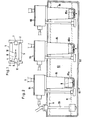
- the weaving machine designated as a whole by 1, contains two side cheeks 2, 3, a warp beam arranged between them. 4 and a goods tree 5, a weft mechanism 6 and a catch mechanism 7 for the projectile 10 entering the weft thread 8 into the shed.
- a pulse lubrication device designated as a whole as 11, for various lubrication points 9 of the weaving machine is attached to the cheek 2.
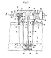
- the lubricating device 11 contains an oil reservoir 62 for the lubricating oil 63.
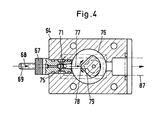
- three oil nebulizer heads 64, 65, 66 are arranged in the example, all of which are of identical design and one of which is shown in FIG. 3, 4.
- Each oil nebulizer head contains an oil nebulizer nozzle 67, to which air pulses (primary pressure) according to arrow 69 are supplied via a channel 68 from a control device. Due to the venturi effect achieved in the channel 71 by enlarging the cross-section, oil is sucked up from the reservoir 62 according to arrow 73 via an intake pipe 72. The oil enters channel 71 via a check valve 74 and a channel 75.
- the parts 78, 79 form a coarse separator for the oil.
- a collecting container 84 is flanged, which is pressure-resistant to the outside and to the oil storage container 62.
- the volume U (eg 50 cm 3 ) of the collecting container 84 is small relative to the volume V (eg 1000 cm 3 ) of the storage container 62.
- the dead volume R (for example 10 cm 3 ) located above the oil level N in the collecting container 84 is also relatively small relative to the dead volume S (for example 200 cm 3 ) above the oil level in the reservoir 62.
- the generated oil mist pulse is conducted via a line 87 into a distribution space 88 and from here on to several lubrication points 17 of the weaving machine 1.
- At the lower end of the collecting container 84 is one of one In the reservoir 62 located float 85 controlled check valve 86 is arranged, through which the volume U is connected to the volume V in the open position.
- a flap valve 86a + can also be used)
- the level in the collecting container 84 drops because of the recurring compensation through the opening 87.
- the dead space R will be used. ++) monitors. this means that it remains larger, but relative to the rooms 76, 88 and the line system 87, it still remains low, so that there is sufficient pressure in each case for the oil mist pulses. in these rooms and in the pipe system to the lubrication points 9.
- the lubricating effect at the lubrication points 17 is therefore practically independent of the instantaneous level of the oil present in the reservoir 62, which can fluctuate between the values N and M.
- FIG. 5 shows, for example, three lubrication points 17a, b, c in the weft housing 25 of the weaving machine.
- Each lubrication point contains a feed line 12a, b, c and a nozzle 9a, b, c.
- oil mist and air impulses are introduced through a spray chamber 29 or 29a during the back and forth movement of the drive sliding piece 28 of a thread feeder or return means, not shown, which runs perpendicular to the plane of the drawing.
- the oil mist partially reaches an opposite baffle 51 of the spray chambers.
- the oil particles reach the surfaces 31 and 31a to be lubricated between the sliding piece 28 and a fixed guide rail 32.
- oil mist and air impulses alternately reach a lubrication point 35 or 34 during the movement of a projectile impact piece 33, which also moves back and forth perpendicular to the plane of the drawing, depending on whether the impact piece 33 covers the nozzle opening 36 or releases it.
- a further lubrication point 17c is provided for the striking piece 33.
- the oil mist pulse coming through the nozzle 9c and the purging air pulse pass through a spray space 37 with a baffle surface 39 in the plane of the drawing and through a spray space 37a behind the plane of the drawing with two lubrication surfaces 38, 41.
- the collecting container 84 projects downward with its lower end 91, which carries the valve 86, in the container 62 so that the valve 86 and the bore 87 lie below the minimum permissible, lower oil level M.
- the suction head 92 of the suction pipe 72 is arranged so deep that it is also below the M level.
- the suction pipe 72 is located outside the collecting container 84 in the storage container 62.
- check valve 86 the plate 93 of which can slide on the rod 94 mounted in the core 79
- another check valve e.g. a flap valve provided with a movable plate can be used.
- the aim is that only oil particles of low weight or volume are contained; the particles of larger oil volume should be separated in the coarse separator 79. In this way, so-called lean lubrication can be achieved. They prevent the fabric or the threads being fed from being contaminated by excessively lubricated machine parts, such as, in particular, by the projectile 10.
- oil mist pulses which emerge from the lubrication points 17 can also be used to clean the lubrication points from fiber fly.
Landscapes
- Engineering & Computer Science (AREA)
- General Engineering & Computer Science (AREA)
- Textile Engineering (AREA)
- Chemical & Material Sciences (AREA)
- Combustion & Propulsion (AREA)
- Oil, Petroleum & Natural Gas (AREA)
- Mechanical Engineering (AREA)
- Auxiliary Weaving Apparatuses, Weavers' Tools, And Shuttles (AREA)
Priority Applications (2)
| Application Number | Priority Date | Filing Date | Title |
|---|---|---|---|
| DE8080810376T DE3068467D1 (en) | 1980-12-02 | 1980-12-02 | Pulse lubricating device for a weaving loom |
| EP19800810376 EP0053218B1 (fr) | 1980-12-02 | 1980-12-02 | Dispositif de lubrification à impulsion d'une machine à tisser |
Applications Claiming Priority (1)
| Application Number | Priority Date | Filing Date | Title |
|---|---|---|---|
| EP19800810376 EP0053218B1 (fr) | 1980-12-02 | 1980-12-02 | Dispositif de lubrification à impulsion d'une machine à tisser |
Publications (2)
| Publication Number | Publication Date |
|---|---|
| EP0053218A1 true EP0053218A1 (fr) | 1982-06-09 |
| EP0053218B1 EP0053218B1 (fr) | 1984-07-04 |
Family
ID=8187468
Family Applications (1)
| Application Number | Title | Priority Date | Filing Date |
|---|---|---|---|
| EP19800810376 Expired EP0053218B1 (fr) | 1980-12-02 | 1980-12-02 | Dispositif de lubrification à impulsion d'une machine à tisser |
Country Status (2)
| Country | Link |
|---|---|
| EP (1) | EP0053218B1 (fr) |
| DE (1) | DE3068467D1 (fr) |
Citations (5)
| Publication number | Priority date | Publication date | Assignee | Title |
|---|---|---|---|---|
| GB105386A (fr) * | 1900-01-01 | |||
| US1960715A (en) * | 1930-07-02 | 1934-05-29 | Motor Improvements Inc | Lubricator |
| US2887181A (en) * | 1956-09-18 | 1959-05-19 | Watts Regulator Co | Air line lubricator |
| GB1227276A (fr) * | 1969-08-13 | 1971-04-07 | ||
| US3606936A (en) * | 1969-12-12 | 1971-09-21 | Houdaille Industries Inc | Oil mist lubrication system |
-
1980
- 1980-12-02 DE DE8080810376T patent/DE3068467D1/de not_active Expired
- 1980-12-02 EP EP19800810376 patent/EP0053218B1/fr not_active Expired
Patent Citations (5)
| Publication number | Priority date | Publication date | Assignee | Title |
|---|---|---|---|---|
| GB105386A (fr) * | 1900-01-01 | |||
| US1960715A (en) * | 1930-07-02 | 1934-05-29 | Motor Improvements Inc | Lubricator |
| US2887181A (en) * | 1956-09-18 | 1959-05-19 | Watts Regulator Co | Air line lubricator |
| GB1227276A (fr) * | 1969-08-13 | 1971-04-07 | ||
| US3606936A (en) * | 1969-12-12 | 1971-09-21 | Houdaille Industries Inc | Oil mist lubrication system |
Also Published As
| Publication number | Publication date |
|---|---|
| EP0053218B1 (fr) | 1984-07-04 |
| DE3068467D1 (en) | 1984-08-09 |
Similar Documents
| Publication | Publication Date | Title |
|---|---|---|
| EP0282049A2 (fr) | Système encreur pour une imprimante matricielle à jet d'encre | |
| DE60113122T2 (de) | Roboter zur vakuumreinigung von schwimmbädern unter druckzufuhr und vefahren | |
| CH650850A5 (de) | Impuls-schmiervorrichtung fuer eine webmaschine. | |
| DE563579C (de) | Strahlregler | |
| EP0053218B1 (fr) | Dispositif de lubrification à impulsion d'une machine à tisser | |
| DE2653220A1 (de) | Webstuhl mit fluidstrahleinschuss | |
| DE2807126A1 (de) | Verfahren und vorrichtung zum vorschieben eines schussfadens bei einem webvorgang | |
| DE4444641C1 (de) | Luftgepulste Setzmaschine mit Abluftabsaugung | |
| DE69010220T2 (de) | Tintenauffänger mit variabler Ausrichtung. | |
| DE2534166A1 (de) | Verfahren und vorrichtung zum reinigen von staubhaltigen gasen | |
| DE865C (de) | Kondensationsvorrichtung an Dampfmaschinen, bestehend aus Vorkondensator und Düsenapparat | |
| DE3315124A1 (de) | Vorrichtung zur erzeugung pulsierend einwirkender mechanischer und hydraulischer energie zum zerkleinern von gestein | |
| DE680323C (de) | Vorrichtung zur selbsttaetigen Grob- und Feinregelung des Austrages der spezifisch schweren Teile des Waschgutes in Kolbensetzmaschinen | |
| DE233112C (fr) | ||
| DE222847C (fr) | ||
| DE111493C (fr) | ||
| DE11394C (de) | Selbstthätiger Dampf kessel - Speiseapparat | |
| DE958330C (de) | Verfahren und Vorrichtung zur Abscheidung von Fluessigkeiten aus Gasen mittels Prallflaechenabscheidern | |
| DE3247290A1 (de) | Hydraulische pumpe | |
| DE2529422A1 (de) | Vorrichtung zur uebernahme von milch aus milchbehaeltern in milchsammelbehaelter, insbesondere milchsammelwagen | |
| DE72755C (de) | Flüssigkeitszerstäuber mit Füllvorrichtung | |
| DE947168C (de) | UEberwachungseinrichtung fuer Dampfwasserableitung | |
| DE102008024605A1 (de) | Vorrichtung zur Regulierung des Saugluftstroms eines Saugers | |
| DE729525C (de) | Vorrichtung zum Einfuehren ungerichtet in einem Fuellschacht liegender Patronen in Magazine usw. | |
| AT113232B (de) | Relais für Regelungsvorrichtungen. |
Legal Events
| Date | Code | Title | Description |
|---|---|---|---|
| PUAI | Public reference made under article 153(3) epc to a published international application that has entered the european phase |
Free format text: ORIGINAL CODE: 0009012 |
|
| 17P | Request for examination filed |
Effective date: 19801204 |
|
| AK | Designated contracting states |
Designated state(s): DE FR GB IT |
|
| RBV | Designated contracting states (corrected) |
Designated state(s): DE FR GB IT |
|
| ITF | It: translation for a ep patent filed | ||
| GRAA | (expected) grant |
Free format text: ORIGINAL CODE: 0009210 |
|
| AK | Designated contracting states |
Designated state(s): DE FR GB IT |
|
| REF | Corresponds to: |
Ref document number: 3068467 Country of ref document: DE Date of ref document: 19840809 |
|
| ET | Fr: translation filed | ||
| PLBE | No opposition filed within time limit |
Free format text: ORIGINAL CODE: 0009261 |
|
| STAA | Information on the status of an ep patent application or granted ep patent |
Free format text: STATUS: NO OPPOSITION FILED WITHIN TIME LIMIT |
|
| 26N | No opposition filed | ||
| PGFP | Annual fee paid to national office [announced via postgrant information from national office to epo] |
Ref country code: FR Payment date: 19881213 Year of fee payment: 9 |
|
| ITTA | It: last paid annual fee | ||
| PGFP | Annual fee paid to national office [announced via postgrant information from national office to epo] |
Ref country code: DE Payment date: 19890131 Year of fee payment: 9 |
|
| PG25 | Lapsed in a contracting state [announced via postgrant information from national office to epo] |
Ref country code: GB Effective date: 19891202 |
|
| GBPC | Gb: european patent ceased through non-payment of renewal fee | ||
| PG25 | Lapsed in a contracting state [announced via postgrant information from national office to epo] |
Ref country code: FR Effective date: 19900831 |
|
| PG25 | Lapsed in a contracting state [announced via postgrant information from national office to epo] |
Ref country code: DE Effective date: 19900901 |
|
| REG | Reference to a national code |
Ref country code: FR Ref legal event code: ST |