EP0053218B1 - Pulse lubricating device for a weaving loom - Google Patents
Pulse lubricating device for a weaving loom Download PDFInfo
- Publication number
- EP0053218B1 EP0053218B1 EP19800810376 EP80810376A EP0053218B1 EP 0053218 B1 EP0053218 B1 EP 0053218B1 EP 19800810376 EP19800810376 EP 19800810376 EP 80810376 A EP80810376 A EP 80810376A EP 0053218 B1 EP0053218 B1 EP 0053218B1
- Authority
- EP
- European Patent Office
- Prior art keywords
- oil
- reservoir
- lubricant
- pressure
- pulse
- Prior art date
- Legal status (The legal status is an assumption and is not a legal conclusion. Google has not performed a legal analysis and makes no representation as to the accuracy of the status listed.)
- Expired
Links
- 230000001050 lubricating effect Effects 0.000 title claims description 9
- 238000009941 weaving Methods 0.000 title claims description 9
- 239000000314 lubricant Substances 0.000 claims description 20
- 239000007921 spray Substances 0.000 claims description 6
- 239000003921 oil Substances 0.000 description 60
- 238000005461 lubrication Methods 0.000 description 32
- 239000003595 mist Substances 0.000 description 23
- 239000006199 nebulizer Substances 0.000 description 11
- 239000002245 particle Substances 0.000 description 7
- 230000007423 decrease Effects 0.000 description 2
- 230000000694 effects Effects 0.000 description 1
- 239000004744 fabric Substances 0.000 description 1
- 239000000835 fiber Substances 0.000 description 1
- 239000010687 lubricating oil Substances 0.000 description 1
- 238000010926 purge Methods 0.000 description 1
- 238000000926 separation method Methods 0.000 description 1
Images


Classifications
-
- D—TEXTILES; PAPER
- D03—WEAVING
- D03J—AUXILIARY WEAVING APPARATUS; WEAVERS' TOOLS; SHUTTLES
- D03J1/00—Auxiliary apparatus combined with or associated with looms
- D03J1/003—Devices for lubricating machine parts
-
- F—MECHANICAL ENGINEERING; LIGHTING; HEATING; WEAPONS; BLASTING
- F16—ENGINEERING ELEMENTS AND UNITS; GENERAL MEASURES FOR PRODUCING AND MAINTAINING EFFECTIVE FUNCTIONING OF MACHINES OR INSTALLATIONS; THERMAL INSULATION IN GENERAL
- F16N—LUBRICATING
- F16N7/00—Arrangements for supplying oil or unspecified lubricant from a stationary reservoir or the equivalent in or on the machine or member to be lubricated
- F16N7/30—Arrangements for supplying oil or unspecified lubricant from a stationary reservoir or the equivalent in or on the machine or member to be lubricated the oil being fed or carried along by another fluid
- F16N7/32—Mist lubrication
- F16N7/34—Atomising devices for oil
Definitions
- the invention relates to a pulse lubrication device for a weaving machine, with a lubricant reservoir, at least one nebulizer sucking the lubricant out of the reservoir and a coarse separator arranged downstream of it and arranged above the reservoir.
- the coarse separator is used to separate the larger lubricant particles from the nebulizer, while the small lubricant particles are fed to the lubrication points of the weaving machine in the form of lubricant mist.
- oil is assumed as the lubricant.
- the larger oil particles separated in the coarse separator are passed into the oil reservoir located below. There is no separation between the coarse separator and the oil reservoir (see e.g. G.B-A-1227276).
- the oil storage container should have a not too small volume of at least one liter or more, so that the Weber oil does not have to be refilled too frequently during operation. If the oil level gradually drops during operation, there is a more and more increasing dead volume in the oil reservoir above the oil level, which forms an air cushion in which the oil mist impulses that leave the nebulizer can be caught. As a result, the pressure in the area between the oil outflow opening of the nebulizer and the lubrication points decreases more and more at the moment of an oil mist pulse as the level in the oil reservoir drops. This also reduces the lubrication intensity, i.e. H. the amount of oil mist emitted at a lubrication point and the intensity of the oil mist also decrease, so that the lubricating effect becomes undesirably less and less during operation.
- the lubrication intensity i.e. H. the amount of oil mist emitted at a lubrication point and the intensity of the oil mist also decrease
- the secondary pressure drops relatively strongly at the lubrication points in the known device with the drop in the level in the oil reservoir with the same pulse duration. This is due to the relatively large dead volume above the level in the reservoir, which occurs when the oil level drops during operation. As a result of this large dead volume, the secondary pressure at the lubrication points also drops in the known device. The consequence of this is that the lubricating effect or the efficiency of the lubrication also deteriorate. This results from the fact that when the secondary pressure drops, a relatively large proportion of oil droplets from the lubricating mist can escape into the environment instead of specifically reaching the respective lubrication point.
- the invention has for its object to provide a pulse lubrication device which is particularly improved in this regard, in particular with a constant pressure of the oil mist pulses to be emitted at the lubrication points, which pressure is independent of the oil level in the oil reservoir.
- the invention consists in that, below the coarse separator, a lubricant collecting container protruding into the storage container is arranged in a pressure-resistant manner, the volume of which is considerably smaller than the volume of the lubricant storage container, and that a check valve is attached to the lower end of the collecting container, which valve is under the current overpressure of a lubricant mist pulse closes and then opens again.
- the collection container designed in this way below the coarse separator can ensure that a relatively small dead volume exists above the oil level in the collection container. This is also relatively small in relation to the volume of the lines or spaces between the oil outlet opening of the nebulizer and the lubrication points. It follows from this that in the event of fluctuations in the dead volume mentioned, the pressure changes (secondary pressure) resulting from the pulse lubrication are also relatively small, so that a practically constant lubricating effect can be achieved at the lubrication points.
- the weaving machine designated as a whole by 1 contains two side cheeks 2, 3, a warp beam 4 arranged in between and a warp beam 5, a weft mechanism 6 and a catch mechanism 7 for the projectile 10 that enters the weft thread 8 into the shed Entire with 11 designated pulse lubrication device for various lubrication points 17 attached to the loom.
- the lubricating device 11 contains an oil reservoir 62 for the lubricating oil 63.
- three oil nebulizer heads 64, 65, 66 are arranged in the example, all of which are of identical design and one of which is shown in FIGS. 3, 4.
- Each oil nebulizer head contains an oil nebulizer nozzle 67, to which air pulses (primary pressure) according to arrow 69 are supplied via a channel 68 from a control device. Because of that Channel 71 Venturi effect achieved by enlarging the cross section is sucked up oil from the reservoir 62 according to arrow 73 via an intake pipe 72.
- the oil enters channel 71 via a check valve 74 and a channel 75.
- the parts 78, 79 form a coarse separator for the oil.
- a collecting container 84 is flanged, which is pressure-resistant to the outside and to the oil reservoir 62.
- the volume U (eg 50 cm 3 ) of the collecting container 84 is small relative to the volume V (eg 1000 cm 3 ) of the storage container 62.
- the dead volume R (for example 10 cm 3 ) located above the oil level N in the collecting container 84 is also relatively small relative to the dead volume S (for example 200 cm 3 ) above the oil level in the reservoir 62.
- the generated oil mist pulse is conducted via a line 97 into a distribution space 88 and from here on to several lubrication points 17 of the weaving machine 1.
- a check valve 86 controlled by a float 85 located in the storage container 62, through which the volume U is connected to the volume V when open.
- a flap valve 86a can also be used.
- the pressure in the rooms 76 and R drops again, so that the check valve 86 is opened under the action of the float 85 moved upward in FIG. 3.
- the level N in the interior of the collecting container 84 and in the storage container 62 can be compensated for, i. H. be brought to the same level.
- a certain amount of oil is separated according to arrow 81 and passed into the collecting container 84, so that the level N in the container 84 can temporarily rise somewhat when the check valve 86 is closed. This increase is compensated for in the following open phase of valve 86, i. H. the excess oil can flow through the opening 87 into the reservoir 62.
- the oil level is monitored by a level monitor 99.
- the level in the collecting container 84 drops because of the recurring compensation through the opening 87.
- the dead space R becomes larger as a result, it still remains small relative to the spaces 76, 88 and the line system 97, so that there is sufficient pressure in each of these spaces and in the line system to the lubrication points 17 in the oil mist pulses.
- the lubricating effect at the lubrication points 17 is therefore practically independent of the instantaneous level of the oil present in the reservoir 62, which can fluctuate between the values N and M.
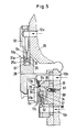
- FIG. 5 shows, for example, three lubrication points 17a, b, c in the weft housing 25 of the weaving machine.
- Each lubrication point contains a feed line 12a, b, c and a nozzle 9a, b, c.
- oil mist and air impulses are introduced through a spray chamber 29 and 29a, respectively, during the back and forth movement of the drive sliding piece 28 of a thread feeder or retractor, not shown, perpendicular to the plane of the drawing.
- the oil mist partially reaches an opposite baffle 51 of the spray chambers.
- the oil particles reach the surfaces 31 and 31 to be lubricated between the sliding piece 28 and a stationary guide rail 32.
- oil mist and air impulses alternately reach a lubrication point 35 or 34 during the movement of a projectile impact piece 33, which also moves back and forth perpendicularly to the plane of the drawing, depending on whether the impact piece 33 covers or clears the nozzle opening 36.
- a further lubrication point 17c is provided for the striking piece 33.
- the oil mist pulse coming through the nozzle 9c and the purging air pulse pass through two spray areas 37 with a baffle surface 39 in the plane of the drawing and two spray areas 38 through a spray room 37a behind the plane of the drawing.
- An opening 61 with a ball valve 60 can be provided for extracting the oil mist (lost oil mist) by suction impulses in a suitable program sequence.
- the collecting container 84 projects so far down in the container 62 that the valve 86 and the bore 87 lie below the minimum permissible lower oil level M.
- the suction head 92 of the suction pipe 72 is arranged so deep that it is also below the M level. As can also be seen from Fig. 3, that is Intake pipe 72 outside the collecting container 84 in the storage container 62.
- check valve 86 the plate 93 of which can slide on the rod 94 mounted in the core 79
- another check element e.g. B. a flap valve 86a provided with a movable plate can be used.
- the aim is that only oil particles of low weight or volume are contained; the particles of larger oil volume should be separated in the coarse separator 78, 79. In this way, so-called lean lubrication can be achieved. They prevent the fabric or the threads being fed from being contaminated by excessively lubricated machine parts, such as, in particular, by the projectile 10.
- the oil mist pulses which emerge from the lubrication points 17 can also be used to clean the lubrication points from fiber fly.
Landscapes
- Engineering & Computer Science (AREA)
- General Engineering & Computer Science (AREA)
- Chemical & Material Sciences (AREA)
- Combustion & Propulsion (AREA)
- Oil, Petroleum & Natural Gas (AREA)
- Mechanical Engineering (AREA)
- Textile Engineering (AREA)
- Auxiliary Weaving Apparatuses, Weavers' Tools, And Shuttles (AREA)
Description
Die Erfindung betrifft eine Impuls-Schmiervorrichtung für eine Webmaschine, mit einem Schmiermittelvorratsbehälter, mindestens einem das Schmiermittel aus dem Vorratsbehälter ansaugenden Vernebler und einem diesem nachgeschalteten, oberhalb des Vorratsbehälters angeordneten Grobabscheider. Der Grobabscheider dient dabei zur Abscheidung der aus dem Vernebler stammenden, grösseren Schmiermittelpartikel, während die kleinen Schmiermittelpartikel in Form von Schmiermittelnebel zu den Schmierstellen der Webmaschine geleitet werden. Im folgenden ist als Schmiermittel beispielsweise Oel angenommen.The invention relates to a pulse lubrication device for a weaving machine, with a lubricant reservoir, at least one nebulizer sucking the lubricant out of the reservoir and a coarse separator arranged downstream of it and arranged above the reservoir. The coarse separator is used to separate the larger lubricant particles from the nebulizer, while the small lubricant particles are fed to the lubrication points of the weaving machine in the form of lubricant mist. In the following, for example, oil is assumed as the lubricant.
Bei einer bisherigen Vorrichtung der genannten Art werden die im Grobabscheider abgetrennten, grösseren Oelpartikel in den darunter befindlichen Oelvorratsbehälter geleitet. Es besteht keine Trennung zwischen Grobabscheider und Oelvorratsbehälter (siehe z. B. G.B-A-1227276).In a previous device of the type mentioned, the larger oil particles separated in the coarse separator are passed into the oil reservoir located below. There is no separation between the coarse separator and the oil reservoir (see e.g. G.B-A-1227276).
Der Oelvorratsbehälter soll ein nicht zu geringes Volumen von mindestens ein Liter oder mehr aufweisen, damit nicht zu häufig durch den Weber Oel während des Betriebes nachgefüllt werden muss. Wenn das Oelniveau während des Betriebes allmählich absinkt, so entsteht oberhalb des Oelniveaus in dem Oelvorratsbehälter ein sich mehr und mehr vergrösserndes Totvolumen, welches ein Luftkissen bildet, in welches die Oelnebelimpulse, welche den Vernebler verlassen, aufgefangen werden können. Dadurch nimmt der Druck in dem Bereich zwischen der Oelausströmöffnung des Verneblers und den Schmierstellen im Moment eines Oelnebelimpulses mit dem Absinken des Niveaus in dem Oelvorratsbehälter mehr und mehr ab. Hierdurch sinkt auch die Schmierintensität, d. h. die an einer Schmierstelle ausgestossene Oelnebelmenge sowie die Intensität des Oelnebels ebenfalls ab, so dass die Schmierwirkung in unerwünschter Weise während des Betriebes immer geringer wird.The oil storage container should have a not too small volume of at least one liter or more, so that the Weber oil does not have to be refilled too frequently during operation. If the oil level gradually drops during operation, there is a more and more increasing dead volume in the oil reservoir above the oil level, which forms an air cushion in which the oil mist impulses that leave the nebulizer can be caught. As a result, the pressure in the area between the oil outflow opening of the nebulizer and the lubrication points decreases more and more at the moment of an oil mist pulse as the level in the oil reservoir drops. This also reduces the lubrication intensity, i.e. H. the amount of oil mist emitted at a lubrication point and the intensity of the oil mist also decrease, so that the lubricating effect becomes undesirably less and less during operation.
Der Sekundärdruck fällt an den Schmierstellen bei der bekannten Vorrichtung mit dem Absinken des Niveaus im Oelvorratsbehälter bei gleicher Impulsdauer verhältnismässig stark ab. Dies ist bedingt durch das relativ grosse Totvolumen oberhalb des Niveaus im Vorratsbehälter, welches bei Absinken des Oelniveaus während des Betriebes entsteht. Infolge dieses grossen Totvolumens sinkt bei der bekannten Vorrichtung auch der Sekundärdruck an den Schmierstellen ab. Die Folge davon ist, dass auch die Schmierwirkung bzw. der Wirkungsgrad der Schmierung nachlassen. Dies ergibt sich daraus, dass bei absinkendem Sekundärdruck ein relativ grosser Anteil von Oeltröpfchen des Schmiernebels in die Umgebung entweichen kann anstatt gezielt auf die jeweilige Schmierstelle zu gelangen.The secondary pressure drops relatively strongly at the lubrication points in the known device with the drop in the level in the oil reservoir with the same pulse duration. This is due to the relatively large dead volume above the level in the reservoir, which occurs when the oil level drops during operation. As a result of this large dead volume, the secondary pressure at the lubrication points also drops in the known device. The consequence of this is that the lubricating effect or the efficiency of the lubrication also deteriorate. This results from the fact that when the secondary pressure drops, a relatively large proportion of oil droplets from the lubricating mist can escape into the environment instead of specifically reaching the respective lubrication point.
Der Erfindung liegt die Aufgabe zugrunde, eine besonders in dieser Hinsicht verbesserte Impuls-Schmiervorrichtung, insbesondere mit konstantem, vom Oelniveau in dem Oelvorratsbehälter unabhängigem Druck der an den Schmierstellen auszustossenden Oelnebelimpulse zu schaffen.The invention has for its object to provide a pulse lubrication device which is particularly improved in this regard, in particular with a constant pressure of the oil mist pulses to be emitted at the lubrication points, which pressure is independent of the oil level in the oil reservoir.
Die Erfindung besteht darin, dass unterhalb des Grobabscheiders ein in den Vorratsbehälter hineinragender Schmiermittelauffangbehälter druckfest angeordnet ist, dessen Volumen relativ zu dem Volumen des Schmiermittelvorratsbehälters wesentlich kleiner ist und dass am unteren Ende des Auffangbehälters ein Rückschlag- ventil angebracht ist, welches unter dem Momentan-Ueberdruck eines Schmiernebelimpulses schliesst und danach wieder öffnet.The invention consists in that, below the coarse separator, a lubricant collecting container protruding into the storage container is arranged in a pressure-resistant manner, the volume of which is considerably smaller than the volume of the lubricant storage container, and that a check valve is attached to the lower end of the collecting container, which valve is under the current overpressure of a lubricant mist pulse closes and then opens again.
Durch den so gestalteten Auffangbehälter unterhalb des Grobabscheiders kann erreicht werden, dass oberhalb des in dem Auffangbehälter befindlichen Oelniveaus ein relativ kleines Totvolumen existiert. Dieses ist relativ zu dem Volumen der Leitungen bzw. Räume zwischen der Oelausströmöffnung des Verneblers und den Schmierstellen ebenfalls verhältnsimässig gering. Hieraus folgt, dass bei Schwankungen des genannten Totvolumens die durch die ImpulsSchmierung entstehenden Druckänderungen (Sekundärdruck) ebenfalls relativ gering sind, so dass sich an den Schmierstellen eine praktisch konstante Schmierwirkung erreichen lässt.The collection container designed in this way below the coarse separator can ensure that a relatively small dead volume exists above the oil level in the collection container. This is also relatively small in relation to the volume of the lines or spaces between the oil outlet opening of the nebulizer and the lubrication points. It follows from this that in the event of fluctuations in the dead volume mentioned, the pressure changes (secondary pressure) resulting from the pulse lubrication are also relatively small, so that a practically constant lubricating effect can be achieved at the lubrication points.
Weitere Merkmale ergeben sich aus der folgenden Beschreibung von Ausführungsbeispielen in Verbindung mit der Zeichnung und den Ansprüchen.
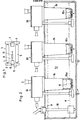
- Figur 1 zeigt eine schematische Draufsicht auf eine Webmaschine mit der erfindungsgemäss ausgebildeten Schmiervorrichtung,
- Figur 2 ist ein Schnitt durch wesentliche Teile der Schmiervorrichtung in grösserem Massstab,
- Figur 3 ist ein Vertikalschnitt durch ein Detail nach Fig. 2, in noch grösserem Massstab,
Figur 4 ein Schnitt nach Linie IV-IV in Fig. 3 undFigur 5 veranschaulicht einige Schmierstellen an der Webmaschine.
- FIG. 1 shows a schematic top view of a weaving machine with the lubrication device designed according to the invention,
- FIG. 2 is a section through essential parts of the lubricating device on a larger scale,
- FIG. 3 is a vertical section through a detail according to FIG. 2, on an even larger scale,
- Figure 4 is a section along line IV-IV in Fig. 3 and
- Figure 5 illustrates some lubrication points on the weaving machine.
Die als Ganzes mit 1 bezeichnete Webmaschine enthält zwei Seitenwangen 2, 3, einen dazwischen angeordneten Kettbaum 4 und einen Warenbaum 5, ein Schusswerk 6 und ein Fangwerk 7 für das den Schussfaden 8 in das Webfach eintragende Projektil 10. An der Wange 2 ist eine als Ganzes mit 11 bezeichnete Impuls-schmiervorrichtung für verschiedene Schmierstellen 17 der Webmaschine angebracht.The weaving machine designated as a whole by 1 contains two side cheeks 2, 3, a
Die Schmiervorrichtung 11 enthält einen Oelvorratsbehälter 62 für das Schmieröl 63. Oberhalb des Vorratsbehälters 62 sind bei dem Beispiel drei Oelverneblerköpfe 64, 65, 66 angeordnet, die sämtlich gleich ausgebildet sind und von denen einer in Fig. 3, 4 dargestellt ist. Jeder Oelverneblerkopf enthält eine Oelverneblerdüse 67, welcher über einen Kanal 68 von einer Steuervorrichtung Luftimpulse (Primärdruck) gemäss Pfeil 69 zugeführt werden. Aufgrund der in dem Kanal 71 durch Querschnittsvergrösserung erzielten Venturi-Wirkung wird über ein Ansaugrohr 72 Oel aus dem Vorratsbehälter 62 entsprechend Pfeil 73 nach oben gesaugt. Das Oel gelangt über ein Rückschlagventil 74 und einen Kanal 75 in den Kanal 71. In diesem wird es mit der zugeführten Luft vermischt, so dass Oelnebel unter Sekundärdruck in einen Raum 76 des Verneblerkopfes gelangt, (vgl. Pfeil 77). Das Oel gelangt auf eine Prallfläche 78 eines nierenförmigen Querschnitt aufweisenden Kernes 79 des Verneblerkopfes 64, wodurch die Oelpartikel von grösserer Gestalt und grösserem Gewicht ausgeschieden werden und gemäss Pfeil 81 absinken.The
Die Teile 78, 79 bilden einen Grobabscheider für das Oel. Unterhalb des Grobabscheiders ist unter Zwischenlage von Dichtungen 82, 83 ein Auffangbehälter 84 angeflanscht, der nach aussen und gegenüber dem Oelvorratsbehälter 62 druckfest ist. Das Volumen U (z. B. 50 cm3) des Auffangbehälters 84 ist relativ zu dem Volumen V (z. B. 1 000 cm3) des Vorratsbehälters 62 gering. Infolgedessen ist auch das oberhalb des Oelniveaus N befindliche Totvolumen R (z. B. 10 cm3) in dem Auffangbehälter 84 relativ zu dem Totvolumen S (z. B. 200 cm3) oberhalb des Oelniveaus im Vorratsbehälter 62 relativ gering.The
Der erzeugte Oelnebelimpuls wird über eine Leitung 97 in einen Verteilraum 88 und von hier weiter zu mehreren Schmierstellen 17 der Webmaschine 1 geleitet.The generated oil mist pulse is conducted via a
Am unteren Ende des Auffangbehälters 84 ist ein von einem in dem Vorratsbehälter 62 befindlichen Schwimmer 85 gesteuertes Rückschlagventil 86 angeordnet, durch welches bei Offenstellung das Volumen U mit dem Volumen V in Verbindung steht. Es kann auch ein Flatterventil 86a benutzt werden.At the lower end of the collecting
Wenn während des Betriebes Luftimpulse unter dem Primärdruck entsprechend Pfeil 69 in den Oelvernebler 64 geleitet werden, stellt sich jedesmal in Raum 76 und dem Totvolumen R kurzfristig der Sekundärdruck ein, durch welchen das Rückschlagventil 86 in die in Fig. 3 dargestellte Schliessstellung geführt wird. Dadurch lässt sich in den Räumen 76, 88 konstanter und genügend grosser Druck aufrechterhalten, so dass während der Oelnebelimpulse eine immer ausreichende Oelnebelmenge zu den Schmierstellen 9 gelangen kann.If, during operation, air pulses under the primary pressure according to
Nach Beendigung eines eingeleiteten Luftimpulses und des zugehörigen Oelnebelimpulses sinkt der Druck in den Räumen 76 und R wieder ab, so dass das Rückschlagventil 86 unter der Wirkung des in Fig. 3 aufwärts bewegten Schwimmers 85 geöffnet wird. Dadurch kann das Niveau N im Innern des Auffangbehälters 84 und im Vorratsbehälter 62 ausgeglichen, d. h. auf gleiche Höhe gebracht werden. Während des Oelnebelimpulses wird entsprechend Pfeil 81 jeweils eine gewisse Oelmenge abgeschieden und in den Auffangbehälter 84 geleitet, so dass bei geschlossenem Rückschlagventil 86 das Niveau N im Behälter 84 vorübergehend etwas ansteigen kann. Dieser Anstieg wird in der folgenden Offenphase des Ventiles 86 ausgeglichen, d. h. das überschüssige Oel kann durch die Oeffnung 87 in den Vorratsbehälter 62 überströmen. Das Ölniveau wird durch einen Niveauwächter 99 überwacht.After the end of an introduced air pulse and the associated oil mist pulse, the pressure in the
Wenn nach einiger Betriebsdauer das Oelniveau N von seinem in Fig. 3 dargestellten Maximalwert absinkt und allmählich auf den Minimalwert M gelangt, so sinkt das Niveau im Auffangbehälter 84 wegen des immer wieder kehrenden Ausgleiches durch die Oeffnung 87 ab. Der Totraum R wird dadurch zwar grösser, aber relativ zu den Räumen 76, 88 und dem Leitungssystem 97 bleibt er immer noch gering, so dass bei den Oelnebelimpulsen jeweils genügend Druck in diesen Räumen und im Leitungssystem zu den Schmierstellen 17 besteht. Die Schmierwirkung an den Schmierstellen 17 ist daher praktisch unabhängig von dem im Vorratsbehälter 62 vorhandenen Momentanniveau des Oeles, das zwischen den Werten N und M schwanken kann.If after a certain period of operation the oil level N drops from its maximum value shown in FIG. 3 and gradually reaches the minimum value M, the level in the collecting
In Fig. 5 sind beispielsweise drei Schmierstellen 17a, b, c im Schusswerkgehäuse 25 der Webmaschine dargestellt. Jede Schmierstelle enthält eine Zuführungsleitung 12a, b, c und eine Düse 9a, b, c. Bei Schmierstelle 17a werden Oelnebel und Luftimpulse während des senkrecht zur Zeichenebene Verlaufenden Hin- und Herganges des Antriebsgleitstückes 28 eines nicht gezeichneten Fadengebers bzw. -rückholers durch einen Sprühraum 29 bzw. 29a eingeleitet. Der Oelnebel gelangt teilweise auf eine gegenüberliegende Prallfläche 51 der Sprühräume. Die Oelpartikel gelangen auf die zu schmierenden Flächen 31 bzw. 31 zwischen dem Gleitstück 28 und einer ortsfesten Führungsschiene 32.5 shows, for example, three
Bei der Schmierstelle 17b gelangen Oelnebel und Luftimpulse während der ebenfalls senkrecht zur Zeichenebene hin- und herverlaufenden Bewegung eines Projektilschlagstückes 33 wechselweise auf eine Schmierstelle 35 bzw. 34, je nachdem ob das Schlagstück 33 die Düsenöffnung 36 abdeckt oder frei gibt.At the
Ausserdem ist eine weitere Schmierstelle 17c für das Schlagstück 33 vorgesehen. Der durch Düse 9c kommende Oelnebelimpuls sowie der Spülluftimpuls gelangen durch einen in der Zeichenebene liegenden Sprühraum 37 mit Prallfläche 39 sowie durch einen hinter der Zeichenebene liegenden Sprühraum 37a auf zwei Schmierflächen 38.In addition, a
Es kann eine Oeffnung 61 mit Kugelventil 60 zum Absaugen des Oelnebels (Verlustölnebel) durch Absaugimpulse in passender Programmfolge vorgesehen sein.An
Wie aus Fig. 3 ersichtlich ist, ragt der Auffangbehälter 84 mit seinem unteren, das Ventil 86 tragenden Ende 91 im Behälter 62 soweit nacht unten, dass Ventil 86 und Bohrung 87 unterhalb des minimal zulässigen, unteren Oelniveaus M liegen. Ebenso ist der Saugkopf 92 des Ansaugrohres 72 so tief angeordnet, dass er ebenfalls unterhalb des Niveaus M liegt. Wie ebenfalls aus Fig. 3 ersichtlich, befindet sich das Ansaugrohr 72 ausserhalb des Auffangbehälters 84 in dem Vorratsbehälter 62.As can be seen from FIG. 3, the collecting
Statt des Rückschlagventiles 86, dessen Teller 93 auf der im Kern 79 angebrachten Stange 94 zu gleiten vermag, kann auch ein anderes Rückschlagorgan, z. B. ein mit einer beweglichen Platte versehenes Flatterventil 86a verwendet werden.Instead of the
Bei dem für die Schmierstellen 17 bestimmten Oelnebel ist angestrebt, dass nur Oelpartikel von geringem Gewicht bzw. Volumen enthalten sind, die Partikel von grösserem Oelvolumen sollen im Grobabscheider 78, 79 abgeschieden werden. Auf diese Weise lässt sich eine sogenannte Magerschmierung erzielen. Durch sie lässt sich vermeiden, dass das Gewebe bzw. die zugeführten Fäden durch übermässig geschmierte Maschinenteile wie insbesondere durch das Projektil 10 verschmutzt werden können.In the case of the oil mist intended for the lubrication points 17, the aim is that only oil particles of low weight or volume are contained; the particles of larger oil volume should be separated in the
- Ferner lässt sich durch die Oelnebelimpulse, welche aus den Schmierstellen 17 treten, auch eine Reinigung der Schmierstellen von Faserflug erzielen.- Furthermore, the oil mist pulses which emerge from the lubrication points 17 can also be used to clean the lubrication points from fiber fly.
Claims (5)
Priority Applications (2)
| Application Number | Priority Date | Filing Date | Title |
|---|---|---|---|
| DE8080810376T DE3068467D1 (en) | 1980-12-02 | 1980-12-02 | Pulse lubricating device for a weaving loom |
| EP19800810376 EP0053218B1 (en) | 1980-12-02 | 1980-12-02 | Pulse lubricating device for a weaving loom |
Applications Claiming Priority (1)
| Application Number | Priority Date | Filing Date | Title |
|---|---|---|---|
| EP19800810376 EP0053218B1 (en) | 1980-12-02 | 1980-12-02 | Pulse lubricating device for a weaving loom |
Publications (2)
| Publication Number | Publication Date |
|---|---|
| EP0053218A1 EP0053218A1 (en) | 1982-06-09 |
| EP0053218B1 true EP0053218B1 (en) | 1984-07-04 |
Family
ID=8187468
Family Applications (1)
| Application Number | Title | Priority Date | Filing Date |
|---|---|---|---|
| EP19800810376 Expired EP0053218B1 (en) | 1980-12-02 | 1980-12-02 | Pulse lubricating device for a weaving loom |
Country Status (2)
| Country | Link |
|---|---|
| EP (1) | EP0053218B1 (en) |
| DE (1) | DE3068467D1 (en) |
Family Cites Families (5)
| Publication number | Priority date | Publication date | Assignee | Title |
|---|---|---|---|---|
| GB105386A (en) * | 1900-01-01 | |||
| US1960715A (en) * | 1930-07-02 | 1934-05-29 | Motor Improvements Inc | Lubricator |
| US2887181A (en) * | 1956-09-18 | 1959-05-19 | Watts Regulator Co | Air line lubricator |
| GB1227276A (en) * | 1969-08-13 | 1971-04-07 | ||
| US3606936A (en) * | 1969-12-12 | 1971-09-21 | Houdaille Industries Inc | Oil mist lubrication system |
-
1980
- 1980-12-02 DE DE8080810376T patent/DE3068467D1/en not_active Expired
- 1980-12-02 EP EP19800810376 patent/EP0053218B1/en not_active Expired
Also Published As
| Publication number | Publication date |
|---|---|
| DE3068467D1 (en) | 1984-08-09 |
| EP0053218A1 (en) | 1982-06-09 |
Similar Documents
| Publication | Publication Date | Title |
|---|---|---|
| EP3851013B1 (en) | Filter cleaning | |
| EP0282049A2 (en) | Ink system for an ink jet matrix printer | |
| DE60113122T2 (en) | ROBOT FOR VACUUM CLEANING OF SWIMMING POOLS UNDER PRESSURE AND EXPERIENCE | |
| CH650850A5 (en) | IMPULSE LUBRICATION DEVICE FOR A WEAVING MACHINE. | |
| DE3002578C2 (en) | Device for degassing a liquid | |
| DE563579C (en) | Aerator | |
| EP0053218B1 (en) | Pulse lubricating device for a weaving loom | |
| DE2653220A1 (en) | LOOM WITH FLUID JET | |
| CH643893A5 (en) | DEVICE FOR INSERTING A WIDE THREAD IN THE POCKET OF A NOZZLE WEAVING MACHINE. | |
| DE4444641C1 (en) | Air=pulsating settling machine for processing minerals | |
| DE69010220T2 (en) | Variable orientation ink catcher. | |
| DE3315124A1 (en) | DEVICE FOR PRODUCING PULSING ACTION MECHANICAL AND HYDRAULIC ENERGY FOR CRUSHING STONE | |
| DE865C (en) | Condensation device on steam engines, consisting of a precondenser and nozzle apparatus | |
| DE2031081A1 (en) | Spray box | |
| DE142812C (en) | ||
| DE958330C (en) | Method and device for separating liquids from gases by means of baffle separators | |
| DE2529422A1 (en) | Milk road tanker transfer system - has valve rod closed by preload spring and float controlled two stage air bleed | |
| DE947168C (en) | Monitoring device for steam water drainage | |
| DE68911526T2 (en) | Device for cleaning flow-conducting tubes. | |
| DE111493C (en) | ||
| DE222847C (en) | ||
| DE574801C (en) | Sieve device | |
| DE102008024605A1 (en) | Device for regulating the suction air flow of a vacuum cleaner | |
| DE325578C (en) | Condensation device with liquid jet pump | |
| DE72755C (en) | Liquid atomizer with filling device |
Legal Events
| Date | Code | Title | Description |
|---|---|---|---|
| PUAI | Public reference made under article 153(3) epc to a published international application that has entered the european phase |
Free format text: ORIGINAL CODE: 0009012 |
|
| 17P | Request for examination filed |
Effective date: 19801204 |
|
| AK | Designated contracting states |
Designated state(s): DE FR GB IT |
|
| RBV | Designated contracting states (corrected) |
Designated state(s): DE FR GB IT |
|
| ITF | It: translation for a ep patent filed | ||
| GRAA | (expected) grant |
Free format text: ORIGINAL CODE: 0009210 |
|
| AK | Designated contracting states |
Designated state(s): DE FR GB IT |
|
| REF | Corresponds to: |
Ref document number: 3068467 Country of ref document: DE Date of ref document: 19840809 |
|
| ET | Fr: translation filed | ||
| PLBE | No opposition filed within time limit |
Free format text: ORIGINAL CODE: 0009261 |
|
| STAA | Information on the status of an ep patent application or granted ep patent |
Free format text: STATUS: NO OPPOSITION FILED WITHIN TIME LIMIT |
|
| 26N | No opposition filed | ||
| PGFP | Annual fee paid to national office [announced via postgrant information from national office to epo] |
Ref country code: FR Payment date: 19881213 Year of fee payment: 9 |
|
| ITTA | It: last paid annual fee | ||
| PGFP | Annual fee paid to national office [announced via postgrant information from national office to epo] |
Ref country code: DE Payment date: 19890131 Year of fee payment: 9 |
|
| PG25 | Lapsed in a contracting state [announced via postgrant information from national office to epo] |
Ref country code: GB Effective date: 19891202 |
|
| GBPC | Gb: european patent ceased through non-payment of renewal fee | ||
| PG25 | Lapsed in a contracting state [announced via postgrant information from national office to epo] |
Ref country code: FR Effective date: 19900831 |
|
| PG25 | Lapsed in a contracting state [announced via postgrant information from national office to epo] |
Ref country code: DE Effective date: 19900901 |
|
| REG | Reference to a national code |
Ref country code: FR Ref legal event code: ST |