EP0053252A1 - Adapter für elektrische Installationsgeräte - Google Patents
Adapter für elektrische Installationsgeräte Download PDFInfo
- Publication number
- EP0053252A1 EP0053252A1 EP81108258A EP81108258A EP0053252A1 EP 0053252 A1 EP0053252 A1 EP 0053252A1 EP 81108258 A EP81108258 A EP 81108258A EP 81108258 A EP81108258 A EP 81108258A EP 0053252 A1 EP0053252 A1 EP 0053252A1
- Authority
- EP
- European Patent Office
- Prior art keywords
- adapter
- busbars
- terminal
- contact
- adapter according
- Prior art date
- Legal status (The legal status is an assumption and is not a legal conclusion. Google has not performed a legal analysis and makes no representation as to the accuracy of the status listed.)
- Granted
Links
- 238000010616 electrical installation Methods 0.000 title description 4
- 238000009434 installation Methods 0.000 claims description 37
- 239000004020 conductor Substances 0.000 claims description 5
- 125000006850 spacer group Chemical group 0.000 claims description 4
- 210000000078 claw Anatomy 0.000 description 7
- 230000005611 electricity Effects 0.000 description 2
- 239000011810 insulating material Substances 0.000 description 2
- 230000000284 resting effect Effects 0.000 description 2
- 238000011161 development Methods 0.000 description 1
- 230000018109 developmental process Effects 0.000 description 1
- 230000007935 neutral effect Effects 0.000 description 1
Images

Classifications
-
- H—ELECTRICITY
- H02—GENERATION; CONVERSION OR DISTRIBUTION OF ELECTRIC POWER
- H02B—BOARDS, SUBSTATIONS OR SWITCHING ARRANGEMENTS FOR THE SUPPLY OR DISTRIBUTION OF ELECTRIC POWER
- H02B1/00—Frameworks, boards, panels, desks, casings; Details of substations or switching arrangements
- H02B1/20—Bus-bar or other wiring layouts, e.g. in cubicles, in switchyards
- H02B1/21—Bus-bar arrangements for rack-mounted devices with withdrawable units
Definitions
- the invention relates to an adapter for installation devices, in particular line circuit breakers, earth leakage circuit breakers and the like, by means of which at least one installation device can be fastened in installation distributors or metering stations directly via current collecting rails.
- a meter space field is in a lower connection space, in which the access-side power supply lines enter Meter field, in which one or more electricity meters are installed, and divided into an upper connection area, in which the consumer-side circuit breakers are located.
- the access-side busbars are on one level in the lower terminal compartment. Electrical installation devices, which are primarily used to interrupt power when working on the house installation and when changing meters, as well as to protect against overload and fault currents, are mounted on adapters above this busbar level. In addition, due to the different regulations of the various energy supply companies, there are often other different installation devices in the lower connection compartment.
- the object of the invention is to dispense with the individual connection terminals for current feed and to carry out the current feed on the adapters for the installation devices.
- the adapter carries connecting parts which can be electrically connected to a busbar and which can be connected to the power supply lines for feeding current to the busbars.
- the connecting parts for the electrical connection of a busbar to a power supply line consist of a contact rail running transversely to the busbars, one end of which can be electrically connected to the current busbar to be connected and the other end of which carries an electrical connection terminal for a power supply line.
- a box terminal, a clamp terminal or a socket terminal can be used as the connecting terminal for the current feed.
- the adapter has a base or a support plate for holding electrical installation devices, in which at least one contact rail serving to feed the current on current busbars is embedded.
- Support plates for holding electrical installation devices with contact rails running transversely to the busbars are known from DE-OS 26 46 123. In the known embodiment, this contact rail is used for the electrical connection of the installation devices to the busbars. However, there is no device for feeding current onto the busbars.
- the contact rails serving the current feed on current busbars can be fastened to the current busbars by insulating contact pieces.
- the contact rails generally also run transversely to the current busbars, but they are not in a compact support plate is embedded.
- Another particularly advantageous embodiment of the adapter according to the invention consists in that its connection parts, which serve for the electrical connection of the current busbars to the power supply lines, have conductors which can be connected to the electrical connection terminals of the installation devices on the access side.
- These conductors are advantageously designed as contact tabs, which are either molded onto the contact rails or onto the connecting terminals for the power supply lines or can be fastened thereon.
- the conductor can advantageously be designed as an electrical connecting line, one end of which can be fastened in the connecting terminal of the contact rail and the other end of which can be fastened in the access-side connecting terminal of the installation device.
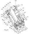
- the adapter 15 essentially consists of a flat base 17, made of insulating material, resting on the busbars 11, 12, 13, 14 and having a vertically angled wall 19 in its end region 18.
- Embedded in the base 17 are three contact rails 20 of different lengths, arranged transversely to the busbars 11, 12, 13, 14, of which only one is visible, which are only exposed to the installation device side of the base 17, but through to the busbar side of the base 17 Insulating material of the base 17 are covered.
- the visible contact rail 20 has a bent portion 21, which is visible through a region shown broken away from the base 17.
- the surface of the offset 21 facing the busbar 13 closes on the one hand with the surface of the base 17 resting on the busbars 11, 12, 13, 14.
- it is screwed to the third busbar 13 by means of a claw 22 and cylinder head screw 23, which results in the necessary contact pressure.
- the claw 22 is angular.
- Your one leg 24 has a non-visible threaded hole for receiving the cylinder head screw 23 and engages behind the busbar 13.
- the other leg 25 is narrower than the first leg 24, engages through a recess 26 located in the base 17 and lies on the front side of the Contact rail 20 on, resulting in a rotation protection for the claw 22.
- the non-cranked end region 27 of the contact rail 20 protrudes from the base 17 in the end region of the base 17 on which the angled wall 19 is formed. It carries a box clamp 30 which has two screws 31 and a wire guard 32. A contact tab 33 is formed on the box terminal 30, which is angled such that its free leg 34 runs parallel to the contact rail 20 and projects over the wall 19 onto the side of the base 17 facing away from the box terminal 30.
- the free leg 34 is tapered in its end region.
- the two invisible contact rails are designed in the same way as the visible contact rail 20. They are arranged parallel to the visible contact rail 20 and likewise protrude from the base 17 with their respective end regions 28, 29. These end regions 28, 29 carry box terminals with molded contact tabs in the same way as the end region 27 of the visible contact rail 20.
- the free leg 44 of the middle contact lug 43 projects into the access-side terminal 35 of the installation device 16.
- the parts of the invisible contact rails which are embedded in the base 17, like the visible contact rail 20, have offsets which are pressed onto the busbars 11, 12 by means of claws and screws.
- the contact rail adjacent to the visible contact rail 20 is connected in this way to the second busbar 12, while the rear contact rail contacts the first, front busbar 11.
- spring elements 38 with U-shaped, bent tabs 39 are snapped into a recess 37 in the end region 36 of the base 17 facing away from the wall 19.
- rectangular stops 40 are formed on the edge of the base 17.
- the base 17 according to Figure 1 is for Suitable for three insiailations 16 mounted next to each other, of which only the middle is shown.
- the free leg 34 of the contact tab 33 is first inserted into the access-side terminal 35 of the installation device 16. Then the installation device 16 is pressed onto the base 17, so that the tab 39 of the Federelenentes38 latches over an invisible projection in the housing of the installation device 16. The wall 19 and the stops 40 ensure that the installation device 16 is fixed in position. Finally, the access-side connecting terminal 35 is tightened so that the installation device 16 is held by the tab 39 of the spring element 38 and by the leg 34 of the contact tab 33.
- the attachment of the adapter 15 to the busbars 11, 12, 13 takes place in the embodiment according to FIG. 1 only via the previously described attachment of the three cranked contact bars 20 embedded in the base 17 on a busbar 11, 12, 13 in each case by means of claws 22 and Cylinder head bolts 23.
- An adapter 15 according to FIG. 1 on the one hand enables direct power supply to the power busbars 11, 12, 13 via feed lines 41 clamped in the box terminals 13.
- installation devices 16 fastened on this adapter 15 can be electrically connected on the access side directly by means of the contact tabs 33.
- FIG. 2 shows an adapter fastened on busbars 51, 52, 53, which carries an installation device 50.
- the adapter consists of three transverse to the busbars 51, 52, 53 and the neutral busbar 54, in essentially exposed contact rails 55, 56 57, each with a claw 58 and a box terminal 59, 60 61. It also consists of two insulating spacers 62, 63 and a top-hat rail 64.
- the contact rails 55, 56, 57 are identical to the contact rails 20 shown in FIG. 1. They are electrically connected with their cranked ends 65 by means of a claw 58 and a screw 66, each with a Stromsawmelschiene 51, 52, 53. In this way, the front contact bar 55 is connected to the third bus bar 53, the middle contact bar 56 to the second bus bar 52 and the rear contact bar 57 to the first bus bar 51. This connection also serves to fasten the adapter to the busbars 51, 52, 53.
- two insulating spacers 62, 63 which have a longitudinal groove on their underside, in which the respective busbar 52, 53 lies, and the top side T- have shaped transverse grooves 69, into which the respective contact rails 55, 56, 57 are inserted upright and then rotated, so that they finally latch in the transverse legs of the T-shaped groove 69 and lie flat over the busbars 51, 52, 53.
- a longitudinally aligned top-hat rail 64 is screwed onto the insulating spacer 62 lying above the middle busbar 52, and an installation device 50 is usually snapped onto it.
- the box terminals 59, 60, 61 of the contact rails 55, 56, 57 differ from those shown in Figure 1 box terminals 30 only in that they do not have any contact tabs.
- the electrical connection of the installation device 50 takes place according to FIG. 2 by a flexible connecting line 67, one end of which is fastened in the box terminal 60 of the contact rail 56 and the other end of which is fastened in the access-side terminal 68 of the installation device 50.
- the current is fed to the busbars 51, 52, 53 via feed lines 71 which are fastened in the box terminals 59, 60, 61.
- a further installation device can be mounted on the adapter on the right and left.
Landscapes
- Engineering & Computer Science (AREA)
- Power Engineering (AREA)
- Installation Of Bus-Bars (AREA)
- Breakers (AREA)
- Distribution Board (AREA)
Abstract
Description
- Die Erfindung betrifft einen Adapter für Installationsgeräte, insbesondere Leitungsschutsschalter, Fehlerstromschutxschalter und dergleichen, mittels dessen wenigstens ein Installationsgerät in Installationsverteilern oder Zählerplätzen direkt über Stromsarnmelschienen befestigbar ist.
- Bei der Hausinstallationsverteilung finden sunehmend Zählerplätze gemäß DIN 43 870 Anwendung. Hiernach ist ein Zählerplatzfeld in einen unteren Anschlußraum, in dem die zugangsseitigen Strcmversorgungsleitungen einlaufen, in ein Zählerfeld, in welchem ein oder mehrere Stromzähler installiert werden, und in einen oberen Anschlußraum, in welchem sich die verbraucherseitigen Sicherungsautomaten befinden, unterteilt.
- Im unteren Anschlußraum liegen die zugangsseitigen Stromsammelschienen in einer Ebene. Elektrische Installationsgeräte, die vor allem der Stromunterbrechung bei Arbeiten an der Hausinstallation und bei Zählerwechsel sowie dem Schutz vor überlast- und Fehlerströmen dienen, werden auf Adapternüber dieser Stromsammelschienenebene montiert. Im unteren Anschlußraum befinden sich darüber hinaus häufig, bedingt durch unterschiedliche Vorschriften der verschiedenen Energieversorgungsunternehmen, weitere unterschiedliche Installationsgeräte.
- Es ist üblich, die Stromsammelschienen mit handelsüblichen Einzel-Anschlußklemmen an die Stromversorgungsleitungen anzuschließen. Da der zur Verfügung stehende Raum durch die Normung begrenzt ist, ist es jedoch oft schwierig, alle diese Installationsgeräte, Befestigungselemente der Stromsammelschienen, Adapter und Einzel-Anschlußklemmen im unteren Anschlußraum unterzubringen. Dies gilt insbesondere in den Fällen, wo mehrere Stromzähler in einem Zählerplatzfeld untergebracht werden sollen, wodurch eine erhöhte Anzahl von Installationsgeräten in dem unteren Anschlußraum untergebracht werden muß. Für den Stromzugang auf die Stromsammelschienen verbleibt dabei kein Raum. Das Einspeisen muß daher über ein zusätzliches Einspeisefeld erfolgen. Dies erfordert jedoch eine größere und damit oft verteuerte Verteilungsanlage.
- Aufgabe der Erfindung ist es, auf die Einzel-Anschlußklemmen zur Stromeinspeisung zu verzichten und die Stromeinspeisung an den Adaptern für die Installationsgeräte vorzunehmen.
- Diese Aufgabe wird erfindungsgemäß dadurch gelöst, daß der Adapter Anschlußteile trägt, die elektrisch mit jeweils einer Stromsammelschiene verbindbar sind und die an die Stromversorgungsleitungen zur Stromeinspeisung auf die Stromsammelschienen anschließbar sind.
- In vorteilhafter Weise bestehen die Anschlußteile zum elektrischen Anschluß einer Stromsammelschiene an eine Stromversorgungsleitung aus einer quer zu den Stromsammelschienen verlaufenden Kontaktschiene, deren eines Ende elektrisch mit der anzuschließenden Stromsamunelschiene verbindbar ist und deren anderes Ende eine elektrische Anschlußklemme für eine Stromversorgungsleitung trägt. Als Anschlußklemme für die Stromeinspeisung kann insbesondere eine Kastenklemme, eine Schellenklemme oder eine Buchsenklemme verwendet werden.
- Einer besonderen Ausgestaltung zur Folge weist der Adapter einen Sockel oder eine Tragplatte zur Halterung von elektrischen Installationsgeräten auf, in dem/der wenigstens eine der Stromeinspeisung auf Stromsammeischienen dienende Kontaktschiene eingebettet ist. Tragplatten zur Halterung von elektrischen Installationsgeräten mit quer zu den Stromsammeischienen verlaufenden Kontaktschienen sind aus der DE-OS 26 46 123 bekannt. In der bekannten Ausführung dient diese Kontaktschiene dem elektrischen Anschluß der Installationsgeräte an die Stromsammelschienen. Es ist dort jedoch keine Vorrichtung zur Stromeinspeisung auf die Stromsammelschienen vorgesehen.
- Eine weitere erfinderische Ausführungsform besteht darin, daß die der Stromeinspeisung auf Stromsammeischienen dienenden Kontaktschienen durch Isolierkontaktstücke auf den Stromsammelschienen befestigbar sind. Bei dieser Ausführungsform verlaufen die Kontaktschienen in der Regel zwar ebenfalls quer zu den Stromsammeischienen, sie sind jedoch nicht in eine kompakte Tragplatte eingebettet. Eine weitere besonders vorteilhafte Ausgestaltung des erfindungsgemäßen Adapters besteht darin, daß seine Anschlußteile, die der elektrischen Verbindung der Stromsammeischienen mit den Stromversorgungsleitungen dienen, Leiter aufweisen, die an die zugangsseitigen elektrischen Anschlußklemmen der Installationsgeräte anschließbar sind.
- Diese Leiter werden in vorteilhafter Weise als Kontaktfahnen ausgebildet, die entweder an die Kontaktschienen oder an die Anschlußklemmen für die Stromversorgungsleitungen angeformt oder an diesen befestigbar sind.
- In einigen Anwendungsfällen läßt sich der Leiter in vorteilhafter Weise als elektrische Verbindungsleitung ausbilden, deren eines Ende in der Anschlußklemme der Kontaktschiene und deren anderes Ende in der zugangsseitigen Anschlußklemme des Installationsgerätes befestigbar ist.
- Anhand der Zeichnung, in der zwei Ausführungsbeispiele der Erfindung gezeigt sind, sollen die Erfindung sowie weitere vorteilhafte Ausgestaltungen und Weiterbildungen näher erläutert werden.
- Es zeigt:
- Figur 1 einen erfindungsgemäßen Adapter mit in einem Sockel eingebetteten Kontaktschienen, mittels dessen ein Installationsgerät über Stromsammelschienen montiert ist, und
- Figur 2 einen erfindungsgemäßen Adapter mit freiliegenden Kontaktschienen, der ebenfalls ein Installationsgerät über Stromsammelschienen trägt.
- Gemäß Figur 1 sind in einem nicht weiter dargestellten Installationsverteilen Stromsammelschienen 11, 12, 13 für drei Phasen sowie eine Nuliaiter-Sammelschiene 14 parallel nebeneinander und in einer Ebene liegend angeordnet. Auf den Sammelschienen 11,12,13,14 ist ein Adapter 15 befestigt, der seinerseits ein Installationsgerät 16 trägt.
- Der Adapter 15 besteht im wesentlichen aus einem flachen, auf den Sammelschienen 11, 12, 13, 14 aufliegenden Sockel 17 aus Isolierstoff, der in seinem Endbereich 18 eine senkrecht abgewinkelte Wand 19 aufweist.
- In dem Sockel 17 sind drei unterschiedlich lange, quer zu den Sammelschienen 11, 12, 13, 14 angeordnete Kontaktschienen 20, von denen nur eine sichtbar ist, eingebettet, die lediglich zur Installationsgeräteseite des Sockels 17 freiliegen, zur Sammelschienenseite des Sockels 17 hin jedoch durch Isoliermaterial des Sockels 17 abgedeckt sind.
- Die sichtbare Kontaktschiene 20 weist in ihrem einen Endbereich eine Abkröpfung 21 auf, die durch einen aus dem Sockel 17 herausgebrochen dargestellten Bereich sichtbar wird. Die der Sammelschiene 13 zugewandte Fläche der Abkröpfung 21 schließt einerseits eben mit der auf den Sammelschienen 11, 12, 13, 14 aufliegenden Fläche des Sockels 17 ab. Sie wird andererseits mit der dritten Stromsammelschiene 13 mittels Pratze 22 und Zylinderkopfschraube 23 verschraubt, wodurch sich der notwendige Kontaktdruck ergibt. Die Pratze 22 ist winkelförmig ausgebildet. Ihr einer Schenkel 24 weist eine nicht sichtbare Gewindebohrung zur Aufnahme der Zylinderkopfschraube 23 auf und hintergreift die Stromsammelschiene 13. Der andere Schenkel 25 ist schmaler als der erste Schenkel 24 ausgebildet, ergreift durch eine in dem Sockel 17 befindliche Ausnehmung 26 und liegt an der Stirnseite der Kontaktschiene 20 an, wodurch sich ein Verdrehschutz für die Pratze 22 ergibt.
- Der nicht abgekröpfte Endbereich 27 der Kontaktschiene 20 ragt in dem Endbereich des Sockels 17, an dem die abgewinkelte Wand 19 angeformt ist, aus dem Sockel 17 heraus. Er trägt eine Kastenklemme 30, welche zwei Schrauben 31 und einen Drahtschutz 32 aufweist. An der Kastenklemme 30 ist eine Kontaktfahne 33 angeformt, welche derart abgewinkelt ist, daß ihr freier Schenkel 34 parallel zur Kontaktschiene 20 verläuft und über die Wand 19 auf die der Kastenklemme 30 abgewandten Seite des Sockels 17 ragt. Der freie Schenkel 34 ist in seinem Endbereich verjüngt ausgebildet.
- Die beiden nicht sichtbaren Kontaktschienen sind in gleicher Weise ausgebildet wie die sichtbare Kontaktschiene 20. Sie sind parallel zu der-sichtbaren Kontaktschiene 20 angeordnet und ragen ebenfalls mit ihrem jeweils einen Endbereich 28, 29 aus dem Sockel 17 heraus. Diese Endbereiche 28, 29 tragen in gleicher Weise wie der Endbereich 27 der sichtbaren Kontaktschiene 20 Kastenklemmen mit angeformten Kontaktfahnen. Der freie Schenkel 44 der mittleren Kontaktfahne 43 ragt in die zugangsseitige Anschlußklemme 35 des Installationsgerätes 16.
- Die in dem Sockel 17 eingebetteten Teile der nicht sichtbaren Kontaktschienen weisen wie die sichtbare Kontaktschiene 20 Abkröpfungen auf, die mittels Pratzen und Schrauben auf die Stromsammelschienen 11, 12 gepreßt werden. Die zur sichtbaren Kontaktschiene 20 benachbarte Kontaktschiene ist auf diese Weise mit der zweiten Stromsammelschiene 12 verbunden, während die hintere Kontaktschiene mit der ersten, vorderen Stromsammelschiene 11 kontaktiert.
- Zur Halterung von Installationsgeräten 16 sind in dem der Wand 19 abgewandten Endbereich 36 des Sockels 17 in einer Ausnehmung 37 Federelemente 38 mit U-förmig abgebogenen, federnden Laschen 39 eingeschnappt. Neben den äußeren Federelementen 38 sind am Rand des Sockels 17 quaderförmige Anschläge 40 angeformt. Der Sockel 17 gemäß Figur 1 ist zur Aufnahme von drei nebeneinander montierten Insiailationsgeräten 16 geeignet, von denen jedoch nur das mittlere dargestellt ist.
- Bei der Montage des Installationsgerätes 16 auf dem Adapter 15 wird zunächst der freie Schenkel 34 der Kontaktfahne 33 in die zugangsseitige Anschlußklemme 35 des Installationsgerätes 16 eingeführt. Dann wird das Installationsgerät 16 auf den Sockel 17 gedrückt, so daß die Lasche 39 des Federelenentes38 über einen nicht sichtbaren Vorsprung im Gehäuse des Installationsgerätes 16 verrastet. Die Wand 19 und die Anschläge 40 besorgen die Lagefixierung des Installationsgerätes 16. Schließlich wird die zugangsseitige Anschlußklemme 35 angezogen, so daß das Installationsgerät 16 von der Lasche 39 des Federelementes 38 und von dem Schenkel 34 der Kontaktfahne 33 gehalten wird.
- Die Befestigung des Adapters 15 auf den Stromsammelschienen 11, 12, 13 erfolgt in dem Ausführungsbeispiel gemäß Figur 1 lediglich über die bereits beschriebene Befestigung der drei abgekröpften, in den Sockel 17 eingebetteten Kontaktschienen 20 auf jeweils einer Stromsammelschiene 11, 12, 13 mittels Pratzen 22 und Zylinderkopfschrauben 23.
- Ein Adapter 15 gemäß Figur 1 ermöglicht einerseits eine direkte Stromeinspeisung auf die Stromsammeischienen 11,12,13 über in den Kastenklemmen 13 eingespannte Einspeiseleitungen 41. Andererseits können auf diesem Adapter 15 befestigte Installationsgeräte 16 zugangsseitig direkt mittels der Kontaktfahnen 33 elektrisch angeschlossen werden.
- Die Figur 2 zeigt einen auf Stromsammelschienen 51, 52, 53 befestigten Adapter, der ein Installationsgerät 50 trägt. Der Adapter besteht aus drei quer zu den Stromsammelschienen 51, 52, 53 sowie der Nulleiter-Sammelschiene 54 verlaufenden, im wesentlichen freiliegenden Kontaktschienen 55, 56 57 mit je einer Pratze 58 und einer Kastenklemme 59, 60 61. Er besteht ferner aus zwei Isolier-Distanzstücken 62,63 und einer Hutprofilschiene 64.
- Die Kontaktschienen 55,56,57 sind identisch wie die in Figur 1 gezeigten Kontaktschienen 20 ausgebildet. Sie sind mit ihren abgekröpften Enden 65 mittels je einer Pratze 58 und einer Schraube 66 mit jeweils einer Stromsawmelschiene 51, 52, 53 elektrisch verbunden. Auf diese Weise ist die vordere Kontaktschiene 55 mit der dritten Stromsammelschiene 53, die mittlere Kontaktschiene 56 mit der zweiten Stromsammelschiene 52 und die hintere Kontaktschiene 57 mit der ersten Stromsammelschiene 51 verbunden. Diese Verbindung dient gleichzeitig der Befestigung des Adapters auf den Stromsammelschienen 51, 52, 53.
- Zur isolierten Abstützung der Kontaktschienen 55, 56, 57 auf den Stromsammelschienen 51, 52, 53 dienen zwei Isolier-Distanzstücke 62, 63, die auf ihrer Unterseite eine Längsnut aufweisen, in der die jeweilige Stromsammelschiene 52, 53 liegt, und deren Oberseite T-förmige Quernuten 69 aufweisen, in die die jeweiligen Kontaktschienen 55, 56, 57 hochkant eingeführt und dann verdreht werden, so daß sie schließlich in den Querschenkeln der T-förmigen Nut 69 verrasten und flach über den Stromsammelschienen 51, 52, 53 liegen.
- Auf dem über der mittleren Stromsammelschiene 52 liegenden Isolier-Distanzstück 62 ist eine längsausgerichtete Hutprofilschiene 64 aufgeschraubt, auf die in üblicherweise ein Installationsgerät 50 aufgeschnappt ist.
- Die Kastenklemmen 59,60, 61 der Kontaktschienen 55, 56, 57 unterscheiden sich von denen in Figur 1 dargestellten Kastenklemmen 30 lediglich dadurch, daß sie keine Kontaktfahnen tragen. Der elektrische Anschluß des Installationsgerätes 50 erfolgt gemäß Figur2 durch eine flexible Verbindungsleitung 67, deren eines Ende in der Kastenklemme 60 der Kontaktschiene 56 und deren anderes Ende in der zugangsseitigen Anschlußklemme 68 des Installationsgerätes 50 befestigt ist. Die Stromeinspeisung auf die Stromsammelschienen 51, 52, 53 erfolgt über Einspeiseleitungen 71, die in den Kastenklemmen 59, 60, 61 befestigt werden.
- Neben dem in Figur 2 dargestellten Installationsgerät 50 lassen sich rechts und links je ein weiteres Installationsgerät auf den Adapter montieren.
Claims (9)
Priority Applications (1)
| Application Number | Priority Date | Filing Date | Title |
|---|---|---|---|
| AT81108258T ATE16542T1 (de) | 1980-12-02 | 1981-10-13 | Adapter fuer elektrische installationsgeraete. |
Applications Claiming Priority (2)
| Application Number | Priority Date | Filing Date | Title |
|---|---|---|---|
| DE19803045358 DE3045358A1 (de) | 1980-12-02 | 1980-12-02 | "adapter fuer installationsgeraete" |
| DE3045358 | 1980-12-02 |
Publications (2)
| Publication Number | Publication Date |
|---|---|
| EP0053252A1 true EP0053252A1 (de) | 1982-06-09 |
| EP0053252B1 EP0053252B1 (de) | 1985-11-13 |
Family
ID=6118079
Family Applications (1)
| Application Number | Title | Priority Date | Filing Date |
|---|---|---|---|
| EP81108258A Expired EP0053252B1 (de) | 1980-12-02 | 1981-10-13 | Adapter für elektrische Installationsgeräte |
Country Status (3)
| Country | Link |
|---|---|
| EP (1) | EP0053252B1 (de) |
| AT (1) | ATE16542T1 (de) |
| DE (1) | DE3045358A1 (de) |
Cited By (7)
| Publication number | Priority date | Publication date | Assignee | Title |
|---|---|---|---|---|
| EP0170161A3 (en) * | 1984-08-03 | 1987-06-16 | Alfred Wohner Gmbh | Installation apparatus for bus-bar systems |
| DE4437011A1 (de) * | 1994-10-15 | 1996-04-18 | Abb Patent Gmbh | Kontaktierungseinrichtung |
| EP0762583A3 (de) * | 1995-08-21 | 1997-09-24 | Weber Ag | Niederspannungs-Sammelschienensystem |
| DE19729410C1 (de) * | 1997-07-09 | 1998-12-03 | Siemens Ag | Elektrische Steckvorrichtung |
| DE102016202023A1 (de) * | 2016-02-10 | 2017-08-10 | Te Connectivity Germany Gmbh | Stromübertragungsvorrichtung mit Überwachungsvorrichtung |
| CN112736597A (zh) * | 2020-12-16 | 2021-04-30 | 国网福建省电力有限公司 | 一种快速转接口的电缆连接件 |
| CN112736598A (zh) * | 2020-12-16 | 2021-04-30 | 国网福建省电力有限公司 | 一种通用接口的电缆连接件 |
Families Citing this family (5)
| Publication number | Priority date | Publication date | Assignee | Title |
|---|---|---|---|---|
| DE3922732C1 (en) * | 1989-07-11 | 1990-10-31 | Rittal-Werk Rudolf Loh Gmbh & Co Kg, 6348 Herborn, De | Device for connecting electrical appts. to terminal rail - uses contact bows to connect bus=bars over guide rail |
| DE19506056C2 (de) * | 1995-02-22 | 1998-10-01 | Peterreins Schalttechnik Gmbh | Adapterplatte zur Anbringung an ein mehrphasiges Stromschienensystem |
| DE29612416U1 (de) * | 1996-07-17 | 1996-09-05 | Abb Patent Gmbh, 68309 Mannheim | Adapter zur Halterung wenigstens eines elektrischen Installationsgerätes an einer Sammelschienenanordnung in einer Installationsverteilung |
| DE10003349B4 (de) * | 2000-01-27 | 2009-02-05 | Abb Ag | Halterungseinrichtung zur Befestigung wenigstens eines elektrischen Schaltgerätes auf einer Hutprofiltragschiene |
| DE102005047045B3 (de) * | 2005-09-30 | 2007-06-21 | Siemens Ag | Anschlussadapter |
Citations (3)
| Publication number | Priority date | Publication date | Assignee | Title |
|---|---|---|---|---|
| US3590332A (en) * | 1969-03-20 | 1971-06-29 | Westinghouse Canada Ltd | Panelboard with insulative circuit breaker supports mounted on the bus bars |
| DE2646123A1 (de) * | 1976-10-13 | 1978-06-29 | Bbc Brown Boveri & Cie | Tragplatte zur halterung von elektrischen installationsgeraeten |
| FR2438359A1 (fr) * | 1978-10-07 | 1980-04-30 | Bbc Brown Boveri & Cie | Systeme a barres omnibus de connexion de materiels electriques encastres d'installation domestique |
Family Cites Families (3)
| Publication number | Priority date | Publication date | Assignee | Title |
|---|---|---|---|---|
| DE1024139B (de) * | 1954-04-10 | 1958-02-13 | Voigt & Haeffner Ag | System fuer elektrische Stromverteilungen unter Verwendung von Installationsgeraeten, insbesondere von Klein-installationsselbstschaltern |
| DE1946714A1 (de) * | 1969-09-16 | 1971-03-25 | Friedel Goedde | Isolierstoffgekapselte Sammelschienen zum drehstrommaessigen Anschliessen von Sicherungs-Schmalautomaten unter Verwendung von steckbaren Anschlussstuecken |
| DE7240787U (de) * | 1972-11-07 | 1973-01-25 | Bbc Ag | Rangierklemme |
-
1980
- 1980-12-02 DE DE19803045358 patent/DE3045358A1/de active Granted
-
1981
- 1981-10-13 AT AT81108258T patent/ATE16542T1/de not_active IP Right Cessation
- 1981-10-13 EP EP81108258A patent/EP0053252B1/de not_active Expired
Patent Citations (3)
| Publication number | Priority date | Publication date | Assignee | Title |
|---|---|---|---|---|
| US3590332A (en) * | 1969-03-20 | 1971-06-29 | Westinghouse Canada Ltd | Panelboard with insulative circuit breaker supports mounted on the bus bars |
| DE2646123A1 (de) * | 1976-10-13 | 1978-06-29 | Bbc Brown Boveri & Cie | Tragplatte zur halterung von elektrischen installationsgeraeten |
| FR2438359A1 (fr) * | 1978-10-07 | 1980-04-30 | Bbc Brown Boveri & Cie | Systeme a barres omnibus de connexion de materiels electriques encastres d'installation domestique |
Cited By (8)
| Publication number | Priority date | Publication date | Assignee | Title |
|---|---|---|---|---|
| EP0170161A3 (en) * | 1984-08-03 | 1987-06-16 | Alfred Wohner Gmbh | Installation apparatus for bus-bar systems |
| DE4437011A1 (de) * | 1994-10-15 | 1996-04-18 | Abb Patent Gmbh | Kontaktierungseinrichtung |
| EP0762583A3 (de) * | 1995-08-21 | 1997-09-24 | Weber Ag | Niederspannungs-Sammelschienensystem |
| DE19729410C1 (de) * | 1997-07-09 | 1998-12-03 | Siemens Ag | Elektrische Steckvorrichtung |
| EP0891012A3 (de) * | 1997-07-09 | 2000-02-02 | Siemens Aktiengesellschaft | Elektrische Steckvorrichtung |
| DE102016202023A1 (de) * | 2016-02-10 | 2017-08-10 | Te Connectivity Germany Gmbh | Stromübertragungsvorrichtung mit Überwachungsvorrichtung |
| CN112736597A (zh) * | 2020-12-16 | 2021-04-30 | 国网福建省电力有限公司 | 一种快速转接口的电缆连接件 |
| CN112736598A (zh) * | 2020-12-16 | 2021-04-30 | 国网福建省电力有限公司 | 一种通用接口的电缆连接件 |
Also Published As
| Publication number | Publication date |
|---|---|
| ATE16542T1 (de) | 1985-11-15 |
| EP0053252B1 (de) | 1985-11-13 |
| DE3045358C2 (de) | 1989-04-20 |
| DE3045358A1 (de) | 1982-07-01 |
Similar Documents
| Publication | Publication Date | Title |
|---|---|---|
| EP0229590B1 (de) | Niederspannungsverteilung | |
| EP0170161B1 (de) | Installationsgerät für Sammelschienensysteme | |
| DE69932764T2 (de) | Abpassbare Abgangsbaugruppe einer Niederspannungs-Schaltzelle | |
| EP0053252B1 (de) | Adapter für elektrische Installationsgeräte | |
| EP0270995B1 (de) | Geräteadapter | |
| DE4327715A1 (de) | Vorrichtung zum Zuführen elektrischer Energie zu wenistens einem elektrischen Installationsgerät | |
| DE4013223C2 (de) | Netzeinspeiseklemme | |
| EP0821454B1 (de) | Anschlussvorrichtung für elektrische Installationsgeräte | |
| EP0252512B1 (de) | Mehrfach-Steckverbindungseinheit | |
| DE2646123A1 (de) | Tragplatte zur halterung von elektrischen installationsgeraeten | |
| EP0762583A2 (de) | Niederspannungs-Sammelschienensystem | |
| DE3813099A1 (de) | Niederspannungsverteiler | |
| DE4440602C2 (de) | Einrichtung zum Sichern von elektrischen Leitungen | |
| EP0262554B1 (de) | Einrichtung zum Verbinden von Installationsgeräten mit Stromsammelschiene eines Grundsammelschienensystems | |
| DE10146503A1 (de) | Elektrische Installationsverteilung | |
| DE9202912U1 (de) | Elektrische Buchsen aufweisender Frontabschluß für elektrische Schränke, Gehäuse, Gestelle od. dgl. | |
| DE10204934A1 (de) | Anschluß- oder Verteilvorrichtung für elektrische Installationsgeräte | |
| EP0975079A2 (de) | Installationsverteiler | |
| EP0818072B1 (de) | Vorrichtung zum anschluss von elektrischen installationsgeräten | |
| DE19639400B4 (de) | System zum Verschienen mit flexiblen isoliergekapselten Stromschienen | |
| DE3427531C2 (de) | ||
| DE3102102C2 (de) | ||
| DE19534690B4 (de) | Abgangskasten für Schienenverteiler | |
| DE8032036U1 (de) | Adapter für Installationsgeräte | |
| EP0872002A1 (de) | Niederspannungs-schaltanlage zur abgabe oder verteilung elektrischer energie |
Legal Events
| Date | Code | Title | Description |
|---|---|---|---|
| PUAI | Public reference made under article 153(3) epc to a published international application that has entered the european phase |
Free format text: ORIGINAL CODE: 0009012 |
|
| AK | Designated contracting states |
Designated state(s): AT BE CH FR GB IT NL |
|
| 17P | Request for examination filed |
Effective date: 19820901 |
|
| ITF | It: translation for a ep patent filed | ||
| GRAA | (expected) grant |
Free format text: ORIGINAL CODE: 0009210 |
|
| AK | Designated contracting states |
Designated state(s): AT BE CH FR GB IT LI NL |
|
| REF | Corresponds to: |
Ref document number: 16542 Country of ref document: AT Date of ref document: 19851115 Kind code of ref document: T |
|
| ET | Fr: translation filed | ||
| PLBE | No opposition filed within time limit |
Free format text: ORIGINAL CODE: 0009261 |
|
| STAA | Information on the status of an ep patent application or granted ep patent |
Free format text: STATUS: NO OPPOSITION FILED WITHIN TIME LIMIT |
|
| 26N | No opposition filed | ||
| PGFP | Annual fee paid to national office [announced via postgrant information from national office to epo] |
Ref country code: GB Payment date: 19900723 Year of fee payment: 10 |
|
| PGFP | Annual fee paid to national office [announced via postgrant information from national office to epo] |
Ref country code: CH Payment date: 19900726 Year of fee payment: 10 |
|
| PGFP | Annual fee paid to national office [announced via postgrant information from national office to epo] |
Ref country code: AT Payment date: 19900806 Year of fee payment: 10 |
|
| ITTA | It: last paid annual fee | ||
| PGFP | Annual fee paid to national office [announced via postgrant information from national office to epo] |
Ref country code: NL Payment date: 19901031 Year of fee payment: 10 Ref country code: BE Payment date: 19901031 Year of fee payment: 10 |
|
| PG25 | Lapsed in a contracting state [announced via postgrant information from national office to epo] |
Ref country code: GB Effective date: 19911013 Ref country code: AT Effective date: 19911013 |
|
| PG25 | Lapsed in a contracting state [announced via postgrant information from national office to epo] |
Ref country code: LI Effective date: 19911031 Ref country code: CH Effective date: 19911031 Ref country code: BE Effective date: 19911031 |
|
| BERE | Be: lapsed |
Owner name: BROWN BOVERI & CIE A.G. Effective date: 19911031 |
|
| PGFP | Annual fee paid to national office [announced via postgrant information from national office to epo] |
Ref country code: FR Payment date: 19920430 Year of fee payment: 11 |
|
| PG25 | Lapsed in a contracting state [announced via postgrant information from national office to epo] |
Ref country code: NL Effective date: 19920501 |
|
| GBPC | Gb: european patent ceased through non-payment of renewal fee | ||
| NLV4 | Nl: lapsed or anulled due to non-payment of the annual fee | ||
| REG | Reference to a national code |
Ref country code: CH Ref legal event code: PL |
|
| PG25 | Lapsed in a contracting state [announced via postgrant information from national office to epo] |
Ref country code: FR Effective date: 19930630 |
|
| REG | Reference to a national code |
Ref country code: FR Ref legal event code: ST |