EP0053284A1 - Colonne de direction de sécurité pour automobiles - Google Patents
Colonne de direction de sécurité pour automobiles Download PDFInfo
- Publication number
- EP0053284A1 EP0053284A1 EP81109082A EP81109082A EP0053284A1 EP 0053284 A1 EP0053284 A1 EP 0053284A1 EP 81109082 A EP81109082 A EP 81109082A EP 81109082 A EP81109082 A EP 81109082A EP 0053284 A1 EP0053284 A1 EP 0053284A1
- Authority
- EP
- European Patent Office
- Prior art keywords
- strands
- steering column
- safety
- fiber
- sleeve
- Prior art date
- Legal status (The legal status is an assumption and is not a legal conclusion. Google has not performed a legal analysis and makes no representation as to the accuracy of the status listed.)
- Granted
Links
Images

Classifications
-
- B—PERFORMING OPERATIONS; TRANSPORTING
- B62—LAND VEHICLES FOR TRAVELLING OTHERWISE THAN ON RAILS
- B62D—MOTOR VEHICLES; TRAILERS
- B62D1/00—Steering controls, i.e. means for initiating a change of direction of the vehicle
- B62D1/02—Steering controls, i.e. means for initiating a change of direction of the vehicle vehicle-mounted
- B62D1/16—Steering columns
- B62D1/18—Steering columns yieldable or adjustable, e.g. tiltable
- B62D1/19—Steering columns yieldable or adjustable, e.g. tiltable incorporating energy-absorbing arrangements, e.g. by being yieldable or collapsible
- B62D1/192—Yieldable or collapsible columns
-
- Y—GENERAL TAGGING OF NEW TECHNOLOGICAL DEVELOPMENTS; GENERAL TAGGING OF CROSS-SECTIONAL TECHNOLOGIES SPANNING OVER SEVERAL SECTIONS OF THE IPC; TECHNICAL SUBJECTS COVERED BY FORMER USPC CROSS-REFERENCE ART COLLECTIONS [XRACs] AND DIGESTS
- Y10—TECHNICAL SUBJECTS COVERED BY FORMER USPC
- Y10T—TECHNICAL SUBJECTS COVERED BY FORMER US CLASSIFICATION
- Y10T74/00—Machine element or mechanism
- Y10T74/20—Control lever and linkage systems
- Y10T74/20396—Hand operated
- Y10T74/20402—Flexible transmitter [e.g., Bowden cable]
- Y10T74/20456—Specific cable or sheath structure
Definitions
- the invention relates to a safety steering column for automobiles according to the preamble of claim 1.
- steering columns today Due to the existing safety regulations, steering columns today have to be designed in such a way that they transmit the torsional moments that occur when the automobile is in motion, with as little torsion as possible, but can deform lengthways in the event of an impact.
- the work taken up by the steering column during the deformation must be reversibly returned in the initial area of the deformation, the steering column remaining functional.
- the steering column may break if the longitudinal deformation increases. However, the force causing the break may not exceed a defined maximum value, since otherwise the driver of the automobile may be injured in the event of an accident.
- the second construction principle used in practice for safety steering columns uses the elastic and plastic properties of metallic materials.
- the safety steering columns here are made, at least in the Be2eLch, which are shortened in the event of an impact, from a metallic grid or corrugated tube.
- the grid and corrugated pipes must be manufactured extremely precisely, since the above-mentioned safety requirements are as precise as possible, i.e. must be complied with virtually without tolerances.
- the production of such safety tubes for steering columns is very difficult and expensive for these reasons.
- even lattice tubes have a very high weight so that the torsional forces occurring during steering movements can be transmitted with little torsion.
- the invention has for its object to provide a steering column with a safety sleeve designed as a grid tube, which is easy to manufacture and with which the safety requirements are met very easily and accurately.
- the steering column or at least the area referred to as the safety sleeve which is shortened in the event of an impact, is wound from fiber-reinforced plastic.
- the security sleeve is made according to a known method wound on a mandrel from one or more impregnated fiber strands, cured and then removed from the mandrel.
- the specific properties of fiber composite materials are used, in particular the directional load-bearing capacity of the winding body in accordance with the selected winding process and the design of the security sleeve also possible by the winding process with regard to very specific desired properties.
- safety steering columns can be produced in this way that precisely meet the above-mentioned properties, but are relatively light and can be produced inexpensively.
- the lattice strands of the lattice-tube-shaped security sleeve which are wound one above the other from individual fiber strands in several layers, preferably have an orientation angle of ⁇ 45 ° with respect to the longitudinal axis of the security sleeve.
- the fiber strands of the lattice strand running in the + 45 ° orientation and the fiber strands of the lattice strand running in the -45 ° orientation are wound one above the other in alternate layers, so that at these points the individual lattice strands are virtually interlocked he follows.
- the requirements for the rigidity of the safety pillar can be varied in a wide range, for. B. by the number of fiber strand layers in the individual lattice strands or by the choice of the width of the wound fiber strands and by the orientation angle which the wound lattice strands make with respect to the longitudinal axis of the security sleeve.
- the orientation of the fiber strands wound on a mandrel is basically freely selectable, but is expediently chosen in such a way that with optimum torsional rigidity and torsional strength the lowest possible longitudinal stiffness and longitudinal strength of the safety sleeve is achieved.
- This optimum is at an orientation angle of ⁇ 45 °, because only then are the individual lattice strands between the crossing points subjected to torsion under tension and compression, but with a longitudinal force on bending and shear.
- the safety sleeve therefore has a high stiffness for torsional forces and a low stiffness for longitudinal forces.
- the strength as well as the rigidity of the individual lattice strands is much greater when loaded in the longitudinal direction than with bending loads, where the breaking of the lattice strands is triggered by interlaminar shear fracture.
- This tendency towards the desired failure in the longitudinal direction can be increased in that with an open network winding of the safety sleeve, the shear areas between the grid strands running in + 45 orientation and in - 45 ° orientation are greatly reduced and thus at the crossing points when the safety sleeve is loaded longitudinally the desired early failure occurs.
- the ratio of height and width of the individual lattice strands can z. B. vary by choosing fiber strands with different widths in combination with the number of winding layers. Even with this possibility, the longitudinal stiffness of the safety sleeve can be changed without the torsional stiffness or strength being influenced too much, since the longitudinal strength of the individual lattice strands on tension and compression only depends on their cross-section, i.e. is independent of the ratio of height to width.
- the security sleeve can, for. B. have a circular cross-section, i.e. the individual fiber strands are wound on a round mandrel.
- the individual lattice strands of the security sleeve are slightly curved in this case, so that the torsional loads not only run in the longitudinal direction of the individual lattice strands, but also have a component perpendicular to the lattice bars. In order to avoid kinking of individual lattice strands in the case of extreme torsional loads, these can be dimensioned accordingly in the winding.
- the security sleeve is preferably wound on a mandrel with the cross section of a regular polygon, so that the security sleeve also has the cross section of a regular polygon.
- the fiber strands are deposited in such a way that the crossing points lie on the edges of the mandrel, that is to say on the polygon edges in the finished safety sleeve.
- the individual lattice strands between two crossing points are straight bars that are almost exclusively stressed in the longitudinal axis under torsional loads and are only at risk of kinking at significantly higher torsional loads than the slightly curved lattice bars of a security sleeve with a circular cross-section.
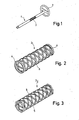
- FIG. 1 part of a steering device of an automobile is shown schematically.
- the steering device consists of a safety steering column 1, the upper end of which is connected to a hand steering wheel 2 and the lower end of which extends into a steering gear (not shown).
- the steering column In its central area, the steering column has a safety sleeve 3 made of fiber-reinforced plastic, which is designed as a lattice tube.
- the remaining parts of the steering column are of conventional construction and are connected coaxially to the safety sleeve 3 by means not shown here.
- FIG. 2 shows a security sleeve 3 1 with a circular cross section.
- the security sleeve is produced by winding fiber strands or rovings impregnated with a synthetic resin binder onto a winding mandrel with a circular cross section according to known techniques.
- the two end sides of the security sleeve are provided with a continuous edge 4 made of fiber-reinforced plastic, between which an open net-shaped structure in the form of a lattice tube extends. This space tube corresponds to a multiple winding pattern with no degree of progress.
- FIG. 4 shows a development of a part of the trellis pattern from intersecting fiber strands.
- each grid strand is composed of several, in this case four layers of flat, impregnated fiber strands 6.
- the longitudinal stiffness of the safety sleeve and thus the safety steering column can be varied by varying the cross section of the lattice strands without significantly influencing the torsional stiffness of the safety sleeve.
- the lattice strands 5 are composed of four layers of flat fiber strands 6, according to FIG. 6B the lattice strands 5 'are also composed of four layers of relatively narrow but strong fiber strands 6'.
- one half of the grid strands 5 runs at an angle ⁇ of + 45 ° with respect to the longitudinal axis 7 of the security sleeve, while the other half of the grid strands runs at an angle of -45 ° to the longitudinal axis 7.
- the safety sleeves are wound in such a way that the fiber strands of the lattice strands 5 with a positive orientation designated by 6 + in FIGS Alternate negative angle orientation.
- the stiffness of the safety sleeve and thus of the safety steering column can also be influenced by the number of layers and the cross section of the fiber strands at the crossing points.
- FIG. 5A four flat but relatively wide fiber strands 6 are used for the grid strands
- FIG. 5B likewise four, but relatively narrow and thick fiber strands 6 'are used for each grid strand.
- there is a relatively large shear area in the embodiment according to FIG. 5B a relatively small shear area, which is shown in dashed lines in this figure.
- a second embodiment of a security sleeve 3 2 which has a cross section of a regular Octagon.
- the security sleeve is wound from fiber strands on a mandrel also with an octagonal cross section, in such a way that the crossing points of the grid strands 5 come to rest on the edges of the mandrel.
- the crossing points 8 of the lattice strands each lie on a line that corresponds to an edge of the polygonal sleeve.
- the lattice strands between each two neighboring crossing points are straight and all of them run in one plane.
- FIG. 4 shows the load force F which occurs during normal operation of the longitudinal column and which acts in the longitudinal direction of the lattice strands.
- this loading force is approximately maintained, so that it also lies in the longitudinal axis of the straight lattice strands.
- the force F has a component perpendicular to the longitudinal axis of the grid strands due to the slightly curved profile of the grid strands 5.
- FIG. 4 the deformation of some lattice strands in the event of an automobile crash is shown in broken lines.
- a safety steering column according to the invention can be adapted to the safety requirements desired for each special case by a corresponding construction made of fiber-reinforced plastic and appropriate dimensioning.
- the manufacture of a steering column according to the invention is simple and inexpensive; in addition, the steering column is light in weight due to the material used.
Landscapes
- Engineering & Computer Science (AREA)
- Chemical & Material Sciences (AREA)
- Combustion & Propulsion (AREA)
- Transportation (AREA)
- Mechanical Engineering (AREA)
- Moulding By Coating Moulds (AREA)
- Steering Controls (AREA)
Applications Claiming Priority (2)
| Application Number | Priority Date | Filing Date | Title |
|---|---|---|---|
| DE3045141 | 1980-11-29 | ||
| DE3045141A DE3045141C2 (de) | 1980-11-29 | 1980-11-29 | Sicherheitslenksäule für Kraftfahrzeuge |
Publications (2)
| Publication Number | Publication Date |
|---|---|
| EP0053284A1 true EP0053284A1 (fr) | 1982-06-09 |
| EP0053284B1 EP0053284B1 (fr) | 1985-05-02 |
Family
ID=6117965
Family Applications (1)
| Application Number | Title | Priority Date | Filing Date |
|---|---|---|---|
| EP81109082A Expired EP0053284B1 (fr) | 1980-11-29 | 1981-10-28 | Colonne de direction de sécurité pour automobiles |
Country Status (4)
| Country | Link |
|---|---|
| US (1) | US4465301A (fr) |
| EP (1) | EP0053284B1 (fr) |
| JP (1) | JPS57114760A (fr) |
| DE (1) | DE3045141C2 (fr) |
Cited By (6)
| Publication number | Priority date | Publication date | Assignee | Title |
|---|---|---|---|---|
| EP0091671A3 (en) * | 1982-04-10 | 1984-04-25 | Audi Nsu Auto Union Aktiengesellschaft | Safety steering column for motor vehicles |
| FR2547259A1 (fr) * | 1983-06-11 | 1984-12-14 | Messerschmitt Boelkow Blohm | Colonne de direction de surete en matieres plastiques renforcees de fibres et enroulees |
| EP0130009A1 (fr) * | 1983-06-18 | 1985-01-02 | Ford Motor Company Limited | Dispositif absorbeur d'énergie |
| FR2558105A1 (fr) * | 1983-06-11 | 1985-07-19 | Messerschmitt Boelkow Blohm | Tube, en particulier pour une colonne de direction de surete pour vehicules automobiles |
| EP0165394A1 (fr) * | 1984-05-23 | 1985-12-27 | Messerschmitt-Bölkow-Blohm Gesellschaft mit beschränkter Haftung | Elément pouvant transmettre des couples |
| DE102015100797A1 (de) | 2015-01-20 | 2016-07-21 | Ford-Werke Gmbh | Plastiklenksäule |
Families Citing this family (15)
| Publication number | Priority date | Publication date | Assignee | Title |
|---|---|---|---|---|
| DE3049425C2 (de) * | 1980-12-30 | 1991-09-05 | Messerschmitt-Bölkow-Blohm GmbH, 8000 München | Aufprall-Schutz-Bauteil |
| JPS5981253A (ja) * | 1982-11-02 | 1984-05-10 | Mitsubishi Electric Corp | 衝撃吸収ステアリングシヤフト |
| JPS6164581A (ja) * | 1984-09-06 | 1986-04-02 | Toyota Motor Corp | 繊維強化樹脂製ステアリングホイ−ル |
| DE3520252A1 (de) * | 1985-06-05 | 1986-12-11 | Metzeler Kautschuk GmbH, 8000 München | Antriebswelle |
| DE3520251A1 (de) * | 1985-06-05 | 1986-12-11 | Metzeler Kautschuk GmbH, 8000 München | Verformbare antriebswelle |
| DE3836685C1 (en) * | 1988-10-28 | 1990-01-25 | Audi Ag, 8070 Ingolstadt, De | Safety steering column for motor vehicles |
| DE3838594A1 (de) * | 1988-11-15 | 1990-05-17 | Kolbenschmidt Ag | Einbauteil zur absorption von energie |
| DE10000286A1 (de) * | 2000-01-07 | 2001-07-26 | Wagon Automotive Gmbh | Aufpralldämpfer |
| GB2368894B (en) * | 2000-11-14 | 2005-07-20 | Nastech Europ Ltd | Steering column assembly for a vehicle |
| US6692026B2 (en) * | 2001-09-13 | 2004-02-17 | Visteon Global Technologies, Inc. | Polymer composite steering column support housing and assembly |
| FR2857323B1 (fr) * | 2003-07-11 | 2005-09-02 | Nacam | Dispositif d'absorption evolutive d'energie d'une colonne de direction de vehicule automobile |
| US20050167963A1 (en) * | 2004-01-30 | 2005-08-04 | Mirjana Jurik | Energy absorbing steering column geometric sleeve |
| DE102016221461B4 (de) | 2016-11-02 | 2020-07-16 | Ford Global Technologies, Llc | Knautschelement für eine Sicherheitslenksäule |
| DE102016221462A1 (de) | 2016-11-02 | 2018-05-03 | Ford Global Technologies, Llc | Knautschelement für eine Sicherheitslenksäule |
| DE202017100169U1 (de) | 2016-11-02 | 2017-03-27 | Ford Global Technologies, Llc | Knautschelement für eine Sicherheitslenksäule |
Citations (4)
| Publication number | Priority date | Publication date | Assignee | Title |
|---|---|---|---|---|
| FR1020948A (fr) * | 1950-06-26 | 1953-02-12 | Diection souple pour automobiles | |
| DE1298010B (de) * | 1966-06-04 | 1969-06-19 | Volkswagenwerk Ag | Sicherheitslenksaeule fuer Kraftfahrzeuge |
| DE2210809A1 (de) * | 1971-03-10 | 1972-09-14 | Societe Quillery, La Garenne Colom bes, Hauts de Seine (Frankreich) | Energieabsorptionsvorrichtung |
| DE2918280A1 (de) * | 1978-05-10 | 1979-11-22 | Textron Inc | Stossdaempfungseinrichtung |
Family Cites Families (10)
| Publication number | Priority date | Publication date | Assignee | Title |
|---|---|---|---|---|
| US3373629A (en) * | 1966-04-29 | 1968-03-19 | Gen Motors Corp | Steering column assembly |
| US3564688A (en) * | 1966-07-14 | 1971-02-23 | Koppy Tool Corp | Method for forming a shock absorbing structural member |
| US3495474A (en) * | 1966-11-24 | 1970-02-17 | Nissan Motor | Impact absorbing means for vehicles |
| US3482466A (en) * | 1967-01-24 | 1969-12-09 | Helmut Orlich | Torsion device for steering columns |
| US3508633A (en) * | 1967-05-17 | 1970-04-28 | Nissan Motor | Plastically deformable impact absorbing means for vehicles |
| JPS492728B1 (fr) * | 1968-12-17 | 1974-01-22 | ||
| DE2150061C3 (de) * | 1971-10-07 | 1975-08-07 | Adam Opel Ag, 6090 Ruesselsheim | Aus Blech bestehendes, plastisch verformbares Deformationsglied für Sicherheitslenkungen von Kraftfahrzeugen |
| US3983963A (en) * | 1972-09-22 | 1976-10-05 | Nissan Motor Co., Ltd. | Multifacially formed panel impact absorber |
| JPS5018248A (fr) * | 1973-06-13 | 1975-02-26 | ||
| DE2738074A1 (de) * | 1976-05-26 | 1979-03-08 | Porsche Ag | Deformationsglied fuer ein kraftfahrzeug |
-
1980
- 1980-11-29 DE DE3045141A patent/DE3045141C2/de not_active Expired
-
1981
- 1981-10-28 EP EP81109082A patent/EP0053284B1/fr not_active Expired
- 1981-11-20 US US06/323,357 patent/US4465301A/en not_active Expired - Fee Related
- 1981-11-28 JP JP56189918A patent/JPS57114760A/ja active Granted
Patent Citations (4)
| Publication number | Priority date | Publication date | Assignee | Title |
|---|---|---|---|---|
| FR1020948A (fr) * | 1950-06-26 | 1953-02-12 | Diection souple pour automobiles | |
| DE1298010B (de) * | 1966-06-04 | 1969-06-19 | Volkswagenwerk Ag | Sicherheitslenksaeule fuer Kraftfahrzeuge |
| DE2210809A1 (de) * | 1971-03-10 | 1972-09-14 | Societe Quillery, La Garenne Colom bes, Hauts de Seine (Frankreich) | Energieabsorptionsvorrichtung |
| DE2918280A1 (de) * | 1978-05-10 | 1979-11-22 | Textron Inc | Stossdaempfungseinrichtung |
Cited By (8)
| Publication number | Priority date | Publication date | Assignee | Title |
|---|---|---|---|---|
| EP0091671A3 (en) * | 1982-04-10 | 1984-04-25 | Audi Nsu Auto Union Aktiengesellschaft | Safety steering column for motor vehicles |
| FR2547259A1 (fr) * | 1983-06-11 | 1984-12-14 | Messerschmitt Boelkow Blohm | Colonne de direction de surete en matieres plastiques renforcees de fibres et enroulees |
| FR2558105A1 (fr) * | 1983-06-11 | 1985-07-19 | Messerschmitt Boelkow Blohm | Tube, en particulier pour une colonne de direction de surete pour vehicules automobiles |
| EP0130009A1 (fr) * | 1983-06-18 | 1985-01-02 | Ford Motor Company Limited | Dispositif absorbeur d'énergie |
| EP0165394A1 (fr) * | 1984-05-23 | 1985-12-27 | Messerschmitt-Bölkow-Blohm Gesellschaft mit beschränkter Haftung | Elément pouvant transmettre des couples |
| DE102015100797A1 (de) | 2015-01-20 | 2016-07-21 | Ford-Werke Gmbh | Plastiklenksäule |
| US9919728B2 (en) | 2015-01-20 | 2018-03-20 | Ford-Werke Gmbh | Steering column made of plastic |
| DE102015100797B4 (de) * | 2015-01-20 | 2021-01-07 | Ford-Werke Gmbh | Plastiklenksäule |
Also Published As
| Publication number | Publication date |
|---|---|
| DE3045141A1 (de) | 1982-06-24 |
| EP0053284B1 (fr) | 1985-05-02 |
| US4465301A (en) | 1984-08-14 |
| JPS57114760A (en) | 1982-07-16 |
| JPH0134183B2 (fr) | 1989-07-18 |
| DE3045141C2 (de) | 1987-07-09 |
Similar Documents
| Publication | Publication Date | Title |
|---|---|---|
| DE3045141C2 (de) | Sicherheitslenksäule für Kraftfahrzeuge | |
| DE3049425C2 (de) | Aufprall-Schutz-Bauteil | |
| DE2611235C2 (de) | Rotorblatt für Drehflügler, insbesondere Hubschrauber | |
| EP2082131B1 (fr) | Mât pour éolienne | |
| DE2942519C2 (fr) | ||
| DE1755897A1 (de) | Kautschukfederelement fuer Fahrzeugaufhaengung od.dgl. | |
| DE2757965A1 (de) | Schubuebertragungselement und verfahren zu dessen herstellung | |
| DE3321198C1 (de) | Sicherheitslenksaeule aus gewickelten faserverstaerkten Kunststoffen | |
| AT392525B (de) | Blattfeder aus faser-kunststoff-verbundwerkstoff | |
| DE2907528C2 (fr) | ||
| EP4263317B1 (fr) | Traverse pour un bogie et son procédé de production | |
| EP3723963B1 (fr) | Procédé de fabrication d'un composant et composant | |
| DE69515426T2 (de) | Versetzbahres Fahrbahnbegrenzungselement, Fahrbahnbegrenzung damit hergestellt und Verfahren zur Herstellung | |
| EP0108870A1 (fr) | Corps porteur de pare-chocs en matière renforcée de fibres pour automobiles ou équivalents | |
| DE3321197C2 (de) | Rohr, insbesondere für eine Sicherheitslenksäule für Kraftfahrzeuge | |
| DE3419176C2 (fr) | ||
| DE3146261A1 (de) | Faserfoermiger zuschlag | |
| DE4425829C1 (de) | Strukturelement im Sandwich-Form | |
| DE2904439C2 (fr) | ||
| EP0033143A1 (fr) | Procédé de fabrication d'écrous-tendeurs | |
| DE3302770A1 (de) | Energieabsorbierendes laminat | |
| DE2201952A1 (de) | Stossverzehrelement, insbesondere fuer kraftfahrzeuge | |
| DE19604275C2 (de) | Verfahren zur Herstellung eines Bauteils | |
| EP0261375A2 (fr) | Procédé pour la fabrication d'une poutre creuse en matériau composite renforcé par des fibres | |
| DE2044995A1 (de) | Ringförmige Reifeneinlage fur Fahr zeugreifen |
Legal Events
| Date | Code | Title | Description |
|---|---|---|---|
| PUAI | Public reference made under article 153(3) epc to a published international application that has entered the european phase |
Free format text: ORIGINAL CODE: 0009012 |
|
| AK | Designated contracting states |
Designated state(s): FR GB IT |
|
| 17P | Request for examination filed |
Effective date: 19820403 |
|
| ITF | It: translation for a ep patent filed | ||
| GRAA | (expected) grant |
Free format text: ORIGINAL CODE: 0009210 |
|
| AK | Designated contracting states |
Designated state(s): FR GB IT |
|
| ET | Fr: translation filed | ||
| PLBE | No opposition filed within time limit |
Free format text: ORIGINAL CODE: 0009261 |
|
| STAA | Information on the status of an ep patent application or granted ep patent |
Free format text: STATUS: NO OPPOSITION FILED WITHIN TIME LIMIT |
|
| 26N | No opposition filed | ||
| PGFP | Annual fee paid to national office [announced via postgrant information from national office to epo] |
Ref country code: GB Payment date: 19900924 Year of fee payment: 10 |
|
| PGFP | Annual fee paid to national office [announced via postgrant information from national office to epo] |
Ref country code: FR Payment date: 19901009 Year of fee payment: 10 |
|
| ITTA | It: last paid annual fee | ||
| PG25 | Lapsed in a contracting state [announced via postgrant information from national office to epo] |
Ref country code: GB Effective date: 19911028 |
|
| GBPC | Gb: european patent ceased through non-payment of renewal fee | ||
| PG25 | Lapsed in a contracting state [announced via postgrant information from national office to epo] |
Ref country code: FR Effective date: 19920630 |
|
| REG | Reference to a national code |
Ref country code: FR Ref legal event code: ST |