EP0053342B1 - Rotor à vis - Google Patents
Rotor à vis Download PDFInfo
- Publication number
- EP0053342B1 EP0053342B1 EP81109853A EP81109853A EP0053342B1 EP 0053342 B1 EP0053342 B1 EP 0053342B1 EP 81109853 A EP81109853 A EP 81109853A EP 81109853 A EP81109853 A EP 81109853A EP 0053342 B1 EP0053342 B1 EP 0053342B1
- Authority
- EP
- European Patent Office
- Prior art keywords
- flank
- rotor member
- rotor
- forward face
- face
- Prior art date
- Legal status (The legal status is an assumption and is not a legal conclusion. Google has not performed a legal analysis and makes no representation as to the accuracy of the status listed.)
- Expired
Links
Images
Classifications
-
- F—MECHANICAL ENGINEERING; LIGHTING; HEATING; WEAPONS; BLASTING
- F04—POSITIVE - DISPLACEMENT MACHINES FOR LIQUIDS; PUMPS FOR LIQUIDS OR ELASTIC FLUIDS
- F04C—ROTARY-PISTON, OR OSCILLATING-PISTON, POSITIVE-DISPLACEMENT MACHINES FOR LIQUIDS; ROTARY-PISTON, OR OSCILLATING-PISTON, POSITIVE-DISPLACEMENT PUMPS
- F04C18/00—Rotary-piston pumps specially adapted for elastic fluids
- F04C18/08—Rotary-piston pumps specially adapted for elastic fluids of intermeshing-engagement type, i.e. with engagement of co-operating members similar to that of toothed gearing
- F04C18/082—Details specially related to intermeshing engagement type pumps
- F04C18/084—Toothed wheels
Definitions
- This invention relates to screw rotors suitable for use with screw compressors, and more particularly it is concerned with the shape and configuration of a screw rotor capable of performing hobbing.
- a screw compressor comprises a male rotor member and a female rotor member forming a pair and maintained in meshing engagement with each other rotatably supported in a casing formed with an inlet port and an outlet port.
- This type of screw compressor generally uses a screw rotor of a tooth profile of nonsymmetrical type in which the forward face of the rotor and the backward face thereof differ from each other in shape and configuration.
- the length of the seal line that is produced between the rotor members has particular bearing on the leak area between the rotor members, and when the seal line has a relatively large length, the leakage increases, thereby causing a reduction in the performance characteristics of the compressor.
- the fluid would leak from the high pressure chamber side to the low pressure chamber side, thereby causing a reduction in the performance characteristics of the compressor.
- the tooth profile is preferably such that the influences exerted by the degree of precision with which the tooth profile of the rotor members is finished on the operation performance of the compressor are minimized. Stated differently, the tooth profile is preferably such that the operation performance is not readily influenced by the degree of precision of the finishes given to the rotor members.
- an improved process which, as compared with a production process relying on a single cutter of the prior art, is capable of producing a screw rotor and which is superior to the prior art process in productivity and precision of finishes given to the screw rotor so that it is suitable for performing hobbing.
- Such process is further preferably capable of producing a screw rotor with a high degree of precision finishes at low cost, with the tools having high dimensional accuracy and a prolonged service life.
- the object of this invention is to provide a screw rotor whose operation performance is improved by minimizing the area of the blow holes and particularly reducing the seal line between the rotor members, which is with a tooth profile capable of increasing the degree of precision of the form of the cutting edge of a hob for generating the teeth of the rotor and prolonging the service life of the hob and which is capable of minimizing mechanical losses that might occur between the tooth surfaces of the rotor members and in the bearings of the rotor.
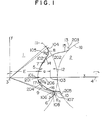
- Fig. 1 shows one embodiment of the screw rotor in conformity with the invention, in which a female rotor member 1 and a male rotor member 2 are shown as rotating in a plane perpendicular to the axis of rotation of the rotor.
- the female rotor member 1 and the male rotor member 2 in meshing engagement with each other rotate in the respective directions indicated by arrows.
- the rotor members 1 and 2 perform the function of a compressor.
- the female rotor member 1 has formed therein a plurality of grooves 5 and projections 6.
- the grooves 5 are each composed of principal parts including a forward face first flank 7, a forward face second flank 8, a backward face first flank 9 and a backward face second flank 10. These principal parts are located inside a pitch circle 11.
- the male rotor member 2 has formed therein a plurality of projections 12 and grooves 13.
- the projections 12 are each composed of principal parts including a forward face first flank 14, a forward face second flank 15, a backward face first flank 16 and a backward face second flank 17. These principal parts are located outside a pitch circle 18.
- the shape and configuration of the grooves 5 of the female rotor member 1 will be described in some detail.
- the forward face first flank 7 of the female rotor member 1 is defined between points 101 and 102.
- the female rotor 1 preferably has an outer diameter D F which is selected such that the ratio of the distance a in the aforesaid formula of parabola to the outer diameter D F is within the range 0.08 :-5 a/ D F ⁇ 0.15.
- the use of a parabolic curve for defining the forward face first flank 7 reduces the rate of slips that occur in the portion of the grooves 5 between the points 101 and 102 of the forward face first flank 7 of the female rotor 1 when motive force is transmitted as the male rotor 2 drives the female rotor 1. This is conducive to minimization of wear that would be caused on the two rotor members 1 and 2 and a reduction in mechanical losses that would occur in the bearings of the rotors, etc.
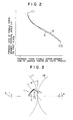
- a solid line A represents changes in the pressure angle a of the forward face first flank 7 of the female rotor member 1 according to the invention
- a dotted line B indicates changes in the pressure angle a of the forward face of the female rotor member of the prior art.
- the pressure angle a in each position of the forward face first flank 7 decreases successively in going from point 101 toward point 102 as indicated by the solid line A and it becomes smaller than the pressure angle a of the female rotor member of the prior art in the vicinity of point 102 on the tooth top side as indicated by the broken line B.
- Fig. 3 shows the forward face first flank 7 of the female rotor member 1 and the forward face first flank 14 of the male rotor member 2 which are in meshing engagement with each other at a certain point at the pressure angle a when the male rotor member 2 rotates in the direction of the arrow to drive the female rotor member 1.
- a force of rotation P t is transmitted from the male rotor member 2 to the female rotor member 1
- the forward face second flank 8 is composed of a portion of the grooves 5 between points 102 and 104 and defined by a circular arc of a radius R 2 centered at a point 105 inside the pitch circle 11.
- the circular arc of the radius R 2 is exessively larger than the circular arc of the radius R 3 defining the backward face second flank 10 of the female rotor member 1.
- the backward face first flank 9 is composed of a portion of the groove between points 101 and 106 which is generated by the circular arc of a backward face tooth top flank 17 of the male rotor member 2.
- the backward face second flank 10 is composed of a portion of the groove 5 between points 106 and 107 which is defined by a circular arc of a radius R 3 centered at a point 108 inside the pitch circle 11.
- the radius R 3 is extremely smaller than the radius R 2 , although it is in the range enabling the service life of the hob cutting tooth top to be sufficiently prolonged to be economical.
- the ratio of the radius R 3 to the radius R 2 is set within the range 0.15 --- R3/ R 2 ⁇ 0.45 to meet the two requirements of prolonging the service life of a hobbing tool and reducing the area of the blow holes without any trouble.
- the lower limit is set by taking into consideration the service life of the tool and the upper limit is decided by being taking into consideration the need to minimize the area of the blow holes.
- the forward face first flank 14 is composed of a portion of the projection 12 between points 201 and 202 and its profile is generated by a parabolic curve of the forward face first flank 7 between points 101 and 102 of the female rotor member 1.
- the portion between points 202 and 203 of the forward face second flank 15 and the portion between points 204 and 205 of the backward face first flank 16 of the male rotor member 2 have a profile generated by a circular arc of the portion between points 102 and 104 of the forward face second flank 8 and the portion between points 106 and 107 of the backward face second flank 10 respectively of the female rotor member 1.
- the profile of the portion between points 201 and 204 of the backward face tooth top flank 17 is formed by a circular arc of a radius R 3 centered at a point 206 on the line connecting together the center points 3 and 4 of the rotary shafts of the two rotors 1 and 2 respectively.
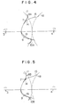
- Fig. 4 and 5 show other embodiments of the invention which are distinct from the embodiment shown in Fig. 1 in that a part or the whole of the forward face second flank 8A, 8B and the backward face second flank 10A, 10B of the female rotor member 1 are located inside or outside the pitch circle 11.
- the forward face first flank and forward face second flank constituting the forward face of the female rotor member are formed by a parabola and a circular arc of a large radius R 2 respectively
- the backward face first flank and the backward face second flank constituting the backward face of the female rotor member are formed by a curve generated by a circular arc of the radius R s on the front side of the male rotor member and a circular arc of the radius R 3 which is extremely smaller than the radius R 2 of the forward face second flank.
Landscapes
- Engineering & Computer Science (AREA)
- Mechanical Engineering (AREA)
- General Engineering & Computer Science (AREA)
- Applications Or Details Of Rotary Compressors (AREA)
- Rotary-Type Compressors (AREA)
Claims (6)
Applications Claiming Priority (2)
| Application Number | Priority Date | Filing Date | Title |
|---|---|---|---|
| JP169574/80 | 1980-12-03 | ||
| JP55169574A JPS5793602A (en) | 1980-12-03 | 1980-12-03 | Screw rotor |
Publications (3)
| Publication Number | Publication Date |
|---|---|
| EP0053342A2 EP0053342A2 (fr) | 1982-06-09 |
| EP0053342A3 EP0053342A3 (en) | 1983-06-08 |
| EP0053342B1 true EP0053342B1 (fr) | 1986-03-05 |
Family
ID=15888994
Family Applications (1)
| Application Number | Title | Priority Date | Filing Date |
|---|---|---|---|
| EP81109853A Expired EP0053342B1 (fr) | 1980-12-03 | 1981-11-24 | Rotor à vis |
Country Status (4)
| Country | Link |
|---|---|
| US (1) | US4406602A (fr) |
| EP (1) | EP0053342B1 (fr) |
| JP (1) | JPS5793602A (fr) |
| DE (1) | DE3174010D1 (fr) |
Families Citing this family (12)
| Publication number | Priority date | Publication date | Assignee | Title |
|---|---|---|---|---|
| US4492546A (en) * | 1981-03-27 | 1985-01-08 | Hitachi, Ltd. | Rotor tooth form for a screw rotor machine |
| DE3278039D1 (en) * | 1982-10-25 | 1988-03-03 | Hitachi Ltd | Screw rotor machine |
| US4583927A (en) * | 1983-03-16 | 1986-04-22 | Kabushiki Kaisha Kobe Seiko Sho | Screw rotor mechanism |
| JPS59196988A (ja) * | 1983-03-16 | 1984-11-08 | Kobe Steel Ltd | スクリユ−圧縮機等のスクリユ−ロ−タ |
| GB8413619D0 (en) * | 1984-05-29 | 1984-07-04 | Compair Ind Ltd | Screw rotor machines |
| JPS61201894A (ja) * | 1985-03-04 | 1986-09-06 | Hitachi Ltd | スクリユ−ロ−タ歯形 |
| US4890992A (en) * | 1988-04-22 | 1990-01-02 | Fu Sheng Industry Co., Ltd. | Screw-rotor machine with an ellipse as a part of its male rotor |
| US5624250A (en) * | 1995-09-20 | 1997-04-29 | Kumwon Co., Ltd. | Tooth profile for compressor screw rotors |
| GB9610289D0 (en) | 1996-05-16 | 1996-07-24 | Univ City | Plural screw positive displacement machines |
| US20060078453A1 (en) * | 2004-10-12 | 2006-04-13 | Fu Sheng Industrial Co. , Ltd. | Mechanism of the screw rotor |
| TWI632298B (zh) * | 2016-04-19 | 2018-08-11 | 日商日立產機系統股份有限公司 | Oil-cooled screw compressor |
| CN111197574B (zh) * | 2018-11-20 | 2021-07-23 | 宿迁学院 | 一种泵用高性能的新抛物线转子 |
Family Cites Families (9)
| Publication number | Priority date | Publication date | Assignee | Title |
|---|---|---|---|---|
| IT454201A (fr) * | 1947-07-16 | |||
| SE312394B (fr) * | 1965-05-10 | 1969-07-14 | A Lysholm | |
| BE792576A (fr) * | 1972-05-24 | 1973-03-30 | Gardner Denver Co | Rotor helicoidal de compresseur a vis |
| US4028026A (en) * | 1972-07-14 | 1977-06-07 | Linde Aktiengesellschaft | Screw compressor with involute profiled teeth |
| US4140445A (en) * | 1974-03-06 | 1979-02-20 | Svenka Rotor Haskiner Aktiebolag | Screw-rotor machine with straight flank sections |
| US4088427A (en) * | 1974-06-24 | 1978-05-09 | Atlas Copco Aktiebolag | Rotors for a screw rotor machine |
| DD122841A1 (fr) * | 1975-11-07 | 1976-11-05 | ||
| JPS53145108A (en) * | 1977-05-25 | 1978-12-18 | Hitachi Ltd | Screw motor |
| JPS6042359B2 (ja) * | 1979-09-14 | 1985-09-21 | 株式会社日立製作所 | スクリユ−ロ−タ |
-
1980
- 1980-12-03 JP JP55169574A patent/JPS5793602A/ja active Granted
-
1981
- 1981-11-24 EP EP81109853A patent/EP0053342B1/fr not_active Expired
- 1981-11-24 DE DE8181109853T patent/DE3174010D1/de not_active Expired
- 1981-12-01 US US06/326,358 patent/US4406602A/en not_active Expired - Lifetime
Also Published As
| Publication number | Publication date |
|---|---|
| JPS5793602A (en) | 1982-06-10 |
| US4406602A (en) | 1983-09-27 |
| EP0053342A3 (en) | 1983-06-08 |
| EP0053342A2 (fr) | 1982-06-09 |
| JPS618241B2 (fr) | 1986-03-13 |
| DE3174010D1 (en) | 1986-04-10 |
Similar Documents
| Publication | Publication Date | Title |
|---|---|---|
| US3787154A (en) | Rotor profiles for helical screw rotor machines | |
| US4435139A (en) | Screw rotor machine and rotor profile therefor | |
| US4406602A (en) | Screw rotor with specific tooth profile | |
| KR101029624B1 (ko) | 내접 기어식 펌프 및 그 펌프의 내측 회전자 | |
| US20220136504A1 (en) | Rotor pair for a compression block of a screw machine | |
| US4527967A (en) | Screw rotor machine with specific tooth profile | |
| JPH0336121B2 (fr) | ||
| KR910002727B1 (ko) | 양변위(positive-displacement) 회전장치 및 그 장치용의 로우터 | |
| US4401420A (en) | Male and female screw rotor assembly with specific tooth flanks | |
| US4028026A (en) | Screw compressor with involute profiled teeth | |
| EP0166531B1 (fr) | Machines à rotors hélicoidaux | |
| US4915604A (en) | Rotors for a screw fluid machine | |
| EP0961009B1 (fr) | Profil de rotor à vis conjugué | |
| US4492546A (en) | Rotor tooth form for a screw rotor machine | |
| EP0211514A1 (fr) | Machine rotative comportant un montage de rotors à vis | |
| USRE21316E (en) | Tooth curve fob rotors and gears | |
| US5624250A (en) | Tooth profile for compressor screw rotors | |
| EP0087239A1 (fr) | Cannelures bombées perfectionnées et définition de leur rayon de base | |
| JPH06123294A (ja) | スクリューロータ | |
| US4671751A (en) | Screw rotor tooth profile | |
| US5135373A (en) | Spur gear with epi-cycloidal and hypo-cycloidal tooth shapes | |
| GB2092676A (en) | Rotary Positive-displacement Fluid-machines | |
| WO1994023206A1 (fr) | Machine hydraulique | |
| GB2299135A (en) | Screw compressor rotor profiles | |
| US4673344A (en) | Screw rotor machine with specific lobe profiles |
Legal Events
| Date | Code | Title | Description |
|---|---|---|---|
| PUAI | Public reference made under article 153(3) epc to a published international application that has entered the european phase |
Free format text: ORIGINAL CODE: 0009012 |
|
| AK | Designated contracting states |
Designated state(s): DE FR GB IT NL SE |
|
| PUAL | Search report despatched |
Free format text: ORIGINAL CODE: 0009013 |
|
| AK | Designated contracting states |
Designated state(s): DE FR GB IT NL SE |
|
| 17P | Request for examination filed |
Effective date: 19830818 |
|
| GRAA | (expected) grant |
Free format text: ORIGINAL CODE: 0009210 |
|
| AK | Designated contracting states |
Kind code of ref document: B1 Designated state(s): DE FR GB IT NL SE |
|
| REF | Corresponds to: |
Ref document number: 3174010 Country of ref document: DE Date of ref document: 19860410 |
|
| ITF | It: translation for a ep patent filed | ||
| ET | Fr: translation filed | ||
| PLBE | No opposition filed within time limit |
Free format text: ORIGINAL CODE: 0009261 |
|
| 26N | No opposition filed | ||
| PGFP | Annual fee paid to national office [announced via postgrant information from national office to epo] |
Ref country code: FR Payment date: 19900922 Year of fee payment: 10 |
|
| PGFP | Annual fee paid to national office [announced via postgrant information from national office to epo] |
Ref country code: GB Payment date: 19900925 Year of fee payment: 10 |
|
| PGFP | Annual fee paid to national office [announced via postgrant information from national office to epo] |
Ref country code: DE Payment date: 19901228 Year of fee payment: 10 |
|
| PG25 | Lapsed in a contracting state [announced via postgrant information from national office to epo] |
Ref country code: GB Effective date: 19911124 |
|
| ITTA | It: last paid annual fee | ||
| GBPC | Gb: european patent ceased through non-payment of renewal fee | ||
| PG25 | Lapsed in a contracting state [announced via postgrant information from national office to epo] |
Ref country code: FR Effective date: 19920731 |
|
| PG25 | Lapsed in a contracting state [announced via postgrant information from national office to epo] |
Ref country code: DE Effective date: 19920801 |
|
| REG | Reference to a national code |
Ref country code: FR Ref legal event code: ST |
|
| EAL | Se: european patent in force in sweden |
Ref document number: 81109853.2 |
|
| PGFP | Annual fee paid to national office [announced via postgrant information from national office to epo] |
Ref country code: SE Payment date: 20000919 Year of fee payment: 20 |
|
| PGFP | Annual fee paid to national office [announced via postgrant information from national office to epo] |
Ref country code: NL Payment date: 20001130 Year of fee payment: 20 |
|
| PG25 | Lapsed in a contracting state [announced via postgrant information from national office to epo] |
Ref country code: NL Free format text: LAPSE BECAUSE OF EXPIRATION OF PROTECTION Effective date: 20011124 |
|
| PG25 | Lapsed in a contracting state [announced via postgrant information from national office to epo] |
Ref country code: SE Free format text: THE PATENT HAS BEEN ANNULLED BY A DECISION OF A NATIONAL AUTHORITY Effective date: 20011129 |
|
| NLV7 | Nl: ceased due to reaching the maximum lifetime of a patent |
Effective date: 20011124 |