EP0053369A1 - Procédé et dispositif pour le traitement thermique d'un carburant liquide - Google Patents
Procédé et dispositif pour le traitement thermique d'un carburant liquide Download PDFInfo
- Publication number
- EP0053369A1 EP0053369A1 EP81109940A EP81109940A EP0053369A1 EP 0053369 A1 EP0053369 A1 EP 0053369A1 EP 81109940 A EP81109940 A EP 81109940A EP 81109940 A EP81109940 A EP 81109940A EP 0053369 A1 EP0053369 A1 EP 0053369A1
- Authority
- EP
- European Patent Office
- Prior art keywords
- heat
- internal combustion
- combustion engine
- fuel
- heat exchanger
- Prior art date
- Legal status (The legal status is an assumption and is not a legal conclusion. Google has not performed a legal analysis and makes no representation as to the accuracy of the status listed.)
- Withdrawn
Links
Images
Classifications
-
- F—MECHANICAL ENGINEERING; LIGHTING; HEATING; WEAPONS; BLASTING
- F02—COMBUSTION ENGINES; HOT-GAS OR COMBUSTION-PRODUCT ENGINE PLANTS
- F02M—SUPPLYING COMBUSTION ENGINES IN GENERAL WITH COMBUSTIBLE MIXTURES OR CONSTITUENTS THEREOF
- F02M31/00—Apparatus for thermally treating combustion-air, fuel, or fuel-air mixture
- F02M31/02—Apparatus for thermally treating combustion-air, fuel, or fuel-air mixture for heating
- F02M31/16—Other apparatus for heating fuel
- F02M31/18—Other apparatus for heating fuel to vaporise fuel
-
- Y—GENERAL TAGGING OF NEW TECHNOLOGICAL DEVELOPMENTS; GENERAL TAGGING OF CROSS-SECTIONAL TECHNOLOGIES SPANNING OVER SEVERAL SECTIONS OF THE IPC; TECHNICAL SUBJECTS COVERED BY FORMER USPC CROSS-REFERENCE ART COLLECTIONS [XRACs] AND DIGESTS
- Y02—TECHNOLOGIES OR APPLICATIONS FOR MITIGATION OR ADAPTATION AGAINST CLIMATE CHANGE
- Y02T—CLIMATE CHANGE MITIGATION TECHNOLOGIES RELATED TO TRANSPORTATION
- Y02T10/00—Road transport of goods or passengers
- Y02T10/10—Internal combustion engine [ICE] based vehicles
- Y02T10/12—Improving ICE efficiencies
Definitions
- the invention relates to a method for the thermal treatment of a liquid fuel for an internal combustion engine, which liquid fuel is conveyed from a store against the combustion chamber part of the internal combustion engine and burned therein. It also relates to a system for carrying out the method, with a storage tank for liquid fuel, a fuel feed line emanating therefrom, a fuel feed line, a fuel pump and a fluid-cooled combustion chamber part.
- Internal combustion engines operated with liquid fuels are gasoline engines and diesel engines, which are designed as two-stroke or four-stroke engines, and which can be engines with pistons carrying out a linear movement and also rotary piston engines.
- the liquid fuel is conveyed against a so-called carburetor, in which the fuel is combined with combustion air to form the so-called mixture, which is a fuel mist, i.e. the fuel is in finely divided droplets, which mixture of the combustion chamber (s) fed to the internal combustion engine and is burned in it.
- the mixture formation does not apply to diesel engines. Instead, the liquid fuel is injected directly into the respective combustion chamber in the form of finely divided droplets.
- the fact that the fuel is in the form of finely divided liquid droplets limits the degree of mixing of the fuel with the combustion air and thus limits the power that can be generated. Furthermore, waste heat is generated during the combustion cycle, which (apart from the passenger compartment heating) is released into the environment unused and to a certain extent represents an environmental pollution.
- the invention seeks to remedy this.
- the invention as characterized in the claims, achieves the object of providing a method for the thermal treatment of a liquid fuel and an amount of heat for carrying out the method in which the fuel is converted from the liquid to the gaseous state, for which purpose the required amount of heat is at least partially taken from the heat loss of the internal combustion engine.
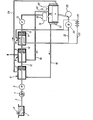
- FIG. Shows schematically an installation for carrying out the method according to the invention.
- the fuel which storage tank is usually called a fuel tank, is stored in a storage tank 1.
- the liquid fuel is introduced into the storage tank 1 through the filler neck 2.
- a fuel feed line 3 extends from the storage tank 1 against a check valve 4.
- This check valve 4 is followed by the known fuel pump 5, viewed in the direction of flow of the fuel.
- the fuel feed line 3 extends from the fuel pump 5 into a first heat exchanger 6.
- This first heat exchanger 6 is a first heat storage 7 assigned.
- the fuel line extends from the first heat exchanger 6 to a second heat exchanger 8.
- a check valve or other control elements can be arranged in the line section 12 of the fuel feed line 3 located between the first and second heat exchangers, but these are not shown for reasons of clarity.
- a second heat accumulator 9 is assigned to the second heat exchanger 8. From this, the fuel feed line 3 runs to a third heat exchanger 10, the line section 12 located between them being able to extend through devices necessary for operation, as mentioned above.
- a third heat accumulator 11 is assigned to the third heat exchanger 10. From this, the fuel feed line 3, as is again designated with the line section 12, leads to a mass flow control valve 13. From this, the line for the now gaseous fuel extends to one Mixture formation chamber 14, which is known under the name "carburetor" and corresponds to the known arrangement of a gasoline engine, the necessary combustion air being supplied at 15.
- the volume flow control valve 13 is followed by an introduction device 14 ′ corresponding to the “injection device” of a diesel engine, in which the gaseous fuel is brought to higher pressure, if necessary, and is introduced into the combustion chamber part 16 in accordance with the work cycles of the diesel engine.
- the known combustion is then carried out in the combustion chamber part 16.
- the exhaust pipe is designated with the reference number 19. Obviously, depending on the type of engine, valves and / or flushing slots are available.
- the exhaust line 19 extends to the second heat exchanger 8.
- a cooling jacket designated by the reference number 17 is arranged around the combustion chamber part 16.
- the cooling fluid contained therein can be a liquid or gaseous substance (cooling air).
- the cooling fluid line 18 extends from the cooling jacket 17 to the first heat exchanger 6.
- a return flow line 24 for the cooling fluid extends from the first heat exchanger 6 and runs back to the cooling jacket 17 of the combustion chamber part 16. This return flow line 24 is obviously only necessary in the case of a closed cooling circuit with a liquid coolant. In the case of an open cooling circuit in which cooling is carried out with air, this return flow line 24 obviously disappears.
- the reference number 21 denotes the known accumulator, the battery of a motor vehicle, from which an electrical line 23 also leads to the third heat exchanger 10.
- any heat loss from the internal combustion engine is used in particular to heat the liquid fuel in order to convert it into a gaseous state.
- Another embodiment is also not shown, in which a quantity of heat used to heat the fuel is also extracted from the lubricating oil of the internal combustion engine.
- the system shown is only one exemplary embodiment of the invention. All that is required is only one heat exchanger, a heat exchange device, in order to be able to carry out the method.
- the fuel feed line 3 is arranged in such a way that it wraps around the exhaust line 19 and a heat exchange device is thus formed.
- the fuel feed line 3 can be led through the exhaust line 19.
- the purpose of the electrical heating shown in the third heat exchanger 10 is to carry out safe operation during a cold start.
- an initial heating of the fuel can be carried out by electrical energy coming from the accumulator 21 and as soon as the internal combustion engine is in operation, the accumulator 21 is switched off and a power generator 20 is connected to it.
- This can be, for example, that of an alternator Motor vehicle associated power generator.
- these electrical apparatuses can be switched off, so that the heat exchange is carried out only with the exhaust gas 19 and, if this version is present, with the cooling fluid 18.
- the fuel first takes heat from the cooling fluid 18 and then from the exhaust gas 19, so that a multi-stage preheating is present.
- a heat accumulator 7; 9; 11 is assigned to each of the three heat exchangers 6; 8; 10. These heat accumulators help to allow the liquid fuel to evaporate quickly when the internal combustion engine starts up, so that a safe start up of the internal combustion engine is ensured.
- any heat loss generated by the internal combustion engine is effectively used to convert the liquid fuel into a gaseous aggregate state, which means not only considerable fuel savings or. higher engine power can be obtained, but the environmental impact can be reduced by the fact that less heat loss is released to the environment.
Landscapes
- Engineering & Computer Science (AREA)
- Chemical & Material Sciences (AREA)
- Combustion & Propulsion (AREA)
- Mechanical Engineering (AREA)
- General Engineering & Computer Science (AREA)
- Feeding And Controlling Fuel (AREA)
- Exhaust Gas After Treatment (AREA)
Applications Claiming Priority (2)
| Application Number | Priority Date | Filing Date | Title |
|---|---|---|---|
| CH8907/80 | 1980-12-02 | ||
| CH890780 | 1980-12-02 |
Publications (1)
| Publication Number | Publication Date |
|---|---|
| EP0053369A1 true EP0053369A1 (fr) | 1982-06-09 |
Family
ID=4346120
Family Applications (1)
| Application Number | Title | Priority Date | Filing Date |
|---|---|---|---|
| EP81109940A Withdrawn EP0053369A1 (fr) | 1980-12-02 | 1981-11-27 | Procédé et dispositif pour le traitement thermique d'un carburant liquide |
Country Status (2)
| Country | Link |
|---|---|
| EP (1) | EP0053369A1 (fr) |
| JP (1) | JPS57176350A (fr) |
Cited By (8)
| Publication number | Priority date | Publication date | Assignee | Title |
|---|---|---|---|---|
| DE3537094A1 (de) * | 1985-10-18 | 1987-04-23 | Janzen Hans Wolfgang | Vergaser fuer brennkraftmaschinen |
| DE4106583A1 (de) * | 1991-03-01 | 1992-09-03 | Schatz Oskar | Verfahren zur beheizung der brennluft von brennkammern mit externer gemischbildung und fluessigem brennstoff |
| WO1993018294A1 (fr) * | 1992-03-03 | 1993-09-16 | Oskar Schatz | Procede de preparation d'un melange combustible a partir d'un carburant liquide et d'un oxydant gazeux, notamment de l'air |
| DE4412448A1 (de) * | 1993-07-09 | 1995-05-18 | Herbert Gladigow | Einrichtung zur Vernebelung von Kraftstoff |
| RU2157460C2 (ru) * | 1998-02-20 | 2000-10-10 | Митьковский Александр Павлович | Устройство для подачи топлива в двигатели внутреннего сгорания |
| RU2201521C2 (ru) * | 2001-03-30 | 2003-03-27 | Конюхов Виталий Алексеевич | Способ смесеобразования двигателя внутреннего сгорания и устройство для смесеобразования двигателя внутреннего сгорания |
| US8857162B2 (en) | 2012-11-02 | 2014-10-14 | Caterpillar Inc. | Coolant warm-up using exhaust |
| CN112983686A (zh) * | 2021-03-17 | 2021-06-18 | 青岛双瑞海洋环境工程股份有限公司 | 双燃料发动机lng供气系统及lng船 |
Citations (5)
| Publication number | Priority date | Publication date | Assignee | Title |
|---|---|---|---|---|
| GB167707A (en) * | 1920-11-01 | 1921-08-18 | Grover Allen Smith | Improvements in vaporizers for internal combustion engines |
| DE2538063A1 (de) * | 1975-08-27 | 1977-03-17 | Sen Helmut Finze | Verfahren zur reduzierung des kraftstoffverbrauchs bei verbrennungsmotoren durch hoehere ausnutzung des kraftstoffes und fuer das verfahren geeignete geraete |
| DE2657806A1 (de) * | 1976-12-21 | 1978-06-22 | Wilhelm Ing Grad Meiners | Benzinverdampfer fuer ottomotoren |
| US4206733A (en) * | 1978-04-06 | 1980-06-10 | Gregory Randy K | Fuel gasifying system |
| US4213433A (en) * | 1977-10-31 | 1980-07-22 | Day John C | Liquid fuel to gas converter for engines |
-
1981
- 1981-11-27 EP EP81109940A patent/EP0053369A1/fr not_active Withdrawn
- 1981-12-02 JP JP56194332A patent/JPS57176350A/ja active Pending
Patent Citations (5)
| Publication number | Priority date | Publication date | Assignee | Title |
|---|---|---|---|---|
| GB167707A (en) * | 1920-11-01 | 1921-08-18 | Grover Allen Smith | Improvements in vaporizers for internal combustion engines |
| DE2538063A1 (de) * | 1975-08-27 | 1977-03-17 | Sen Helmut Finze | Verfahren zur reduzierung des kraftstoffverbrauchs bei verbrennungsmotoren durch hoehere ausnutzung des kraftstoffes und fuer das verfahren geeignete geraete |
| DE2657806A1 (de) * | 1976-12-21 | 1978-06-22 | Wilhelm Ing Grad Meiners | Benzinverdampfer fuer ottomotoren |
| US4213433A (en) * | 1977-10-31 | 1980-07-22 | Day John C | Liquid fuel to gas converter for engines |
| US4206733A (en) * | 1978-04-06 | 1980-06-10 | Gregory Randy K | Fuel gasifying system |
Cited By (9)
| Publication number | Priority date | Publication date | Assignee | Title |
|---|---|---|---|---|
| DE3537094A1 (de) * | 1985-10-18 | 1987-04-23 | Janzen Hans Wolfgang | Vergaser fuer brennkraftmaschinen |
| DE4106583A1 (de) * | 1991-03-01 | 1992-09-03 | Schatz Oskar | Verfahren zur beheizung der brennluft von brennkammern mit externer gemischbildung und fluessigem brennstoff |
| WO1993018294A1 (fr) * | 1992-03-03 | 1993-09-16 | Oskar Schatz | Procede de preparation d'un melange combustible a partir d'un carburant liquide et d'un oxydant gazeux, notamment de l'air |
| DE4412448A1 (de) * | 1993-07-09 | 1995-05-18 | Herbert Gladigow | Einrichtung zur Vernebelung von Kraftstoff |
| DE4412448C2 (de) * | 1993-07-09 | 1998-02-12 | Herbert Gladigow | Einrichtung zur Vernebelung von Kraftstoff |
| RU2157460C2 (ru) * | 1998-02-20 | 2000-10-10 | Митьковский Александр Павлович | Устройство для подачи топлива в двигатели внутреннего сгорания |
| RU2201521C2 (ru) * | 2001-03-30 | 2003-03-27 | Конюхов Виталий Алексеевич | Способ смесеобразования двигателя внутреннего сгорания и устройство для смесеобразования двигателя внутреннего сгорания |
| US8857162B2 (en) | 2012-11-02 | 2014-10-14 | Caterpillar Inc. | Coolant warm-up using exhaust |
| CN112983686A (zh) * | 2021-03-17 | 2021-06-18 | 青岛双瑞海洋环境工程股份有限公司 | 双燃料发动机lng供气系统及lng船 |
Also Published As
| Publication number | Publication date |
|---|---|
| JPS57176350A (en) | 1982-10-29 |
Similar Documents
| Publication | Publication Date | Title |
|---|---|---|
| DE3323337C2 (de) | Verfahren zum Betreiben einer Dieselbrennkraftmaschine | |
| DE2640243A1 (de) | Hydridkraftstoffanlage fuer verbrennungsmaschinen | |
| DE2525585C2 (de) | Verfahren zum Betreiben einer Verbrennungskraftmaschine für den Unterwassereinsatz | |
| DE2130986A1 (de) | Gasmaschine | |
| DE19706090A1 (de) | Antriebssystem für ein Kraftfahrzeug | |
| DE19913795C1 (de) | Vorrichtung mit einer Brennkraftmaschine und mit einem Brennstoffzellensystem | |
| DE1062986B (de) | Gasturbinenanlage mit Hilfsaggregaten | |
| EP0053369A1 (fr) | Procédé et dispositif pour le traitement thermique d'un carburant liquide | |
| DE2421938A1 (de) | Anordnung zur fernhaltung von wasser aus einer kraftstoffanlage | |
| DE3432512C2 (de) | Vorrichtung und Verfahren zum Vorglühen des Motorblocks einer Brennkraftmaschine oder der Brennkraftmaschinen-Ansaugluft | |
| DE102019110249A1 (de) | Wasserstoffmotor mit Wassereinspritzung | |
| DE3322168A1 (de) | Dieselbrennkraftmaschine | |
| DE2422672A1 (de) | Pressdruckluftmotor | |
| EP0231223B1 (fr) | Moteur diesel | |
| DE3429727A1 (de) | Brennkraft/dampf-verbundmotor mit nutzung der prozesswaerme | |
| DE2004579A1 (de) | Verbrennungsmotor | |
| DE2826834A1 (de) | Verbundverbrennungsmotor | |
| DE102019106722A1 (de) | Verbrennungsmotor und Verfahren zum Betrieb dieses Verbrennungsmotors | |
| DE2732315A1 (de) | Verbrennungsmotor, insbesondere zweitaktmotor | |
| DE725757C (de) | Brennkraftmaschine | |
| DE2949152A1 (de) | Anlasshilfevorrichtung fuer einen dieselmotor | |
| DE3005373C2 (de) | Verfahren und Vorrichtung zum Starten wasserstoffbetriebener Motore | |
| DE2428623A1 (de) | Verfahren zur herabsetzung der temperatur in verbrennungsmotoren | |
| DE349563C (de) | Einrichtung zum Betrieb von Kraftmaschinen mit Verbrennungsgasen und Fluessigkeiten | |
| DE572395C (de) | Verfahren zur Gewinnung eines Druckmittels zur Fernkraftuebertragung |
Legal Events
| Date | Code | Title | Description |
|---|---|---|---|
| PUAI | Public reference made under article 153(3) epc to a published international application that has entered the european phase |
Free format text: ORIGINAL CODE: 0009012 |
|
| STAA | Information on the status of an ep patent application or granted ep patent |
Free format text: STATUS: THE APPLICATION HAS BEEN WITHDRAWN |
|
| AK | Designated contracting states |
Designated state(s): AT BE DE FR GB IT LU NL SE |
|
| 18W | Application withdrawn |
Withdrawal date: 19820517 |
|
| RIN1 | Information on inventor provided before grant (corrected) |
Inventor name: JOVY, HERBERT, DR. |