EP0053370A2 - Method to control a hydraulic mechanism, and hydraulic mechanism suited to carry out said method - Google Patents
Method to control a hydraulic mechanism, and hydraulic mechanism suited to carry out said method Download PDFInfo
- Publication number
- EP0053370A2 EP0053370A2 EP81109942A EP81109942A EP0053370A2 EP 0053370 A2 EP0053370 A2 EP 0053370A2 EP 81109942 A EP81109942 A EP 81109942A EP 81109942 A EP81109942 A EP 81109942A EP 0053370 A2 EP0053370 A2 EP 0053370A2
- Authority
- EP
- European Patent Office
- Prior art keywords
- piston
- pressure
- hydraulic drive
- hydraulic
- drive according
- Prior art date
- Legal status (The legal status is an assumption and is not a legal conclusion. Google has not performed a legal analysis and makes no representation as to the accuracy of the status listed.)
- Granted
Links
- 238000000034 method Methods 0.000 title claims abstract description 23
- 230000001133 acceleration Effects 0.000 claims description 13
- 238000003825 pressing Methods 0.000 abstract 1
- 238000010586 diagram Methods 0.000 description 3
- 239000012530 fluid Substances 0.000 description 3
- 230000007704 transition Effects 0.000 description 1
Images
Classifications
-
- F—MECHANICAL ENGINEERING; LIGHTING; HEATING; WEAPONS; BLASTING
- F15—FLUID-PRESSURE ACTUATORS; HYDRAULICS OR PNEUMATICS IN GENERAL
- F15B—SYSTEMS ACTING BY MEANS OF FLUIDS IN GENERAL; FLUID-PRESSURE ACTUATORS, e.g. SERVOMOTORS; DETAILS OF FLUID-PRESSURE SYSTEMS, NOT OTHERWISE PROVIDED FOR
- F15B11/00—Servomotor systems without provision for follow-up action; Circuits therefor
- F15B11/02—Systems essentially incorporating special features for controlling the speed or actuating force of an output member
- F15B11/04—Systems essentially incorporating special features for controlling the speed or actuating force of an output member for controlling the speed
- F15B11/046—Systems essentially incorporating special features for controlling the speed or actuating force of an output member for controlling the speed depending on the position of the working member
- F15B11/048—Systems essentially incorporating special features for controlling the speed or actuating force of an output member for controlling the speed depending on the position of the working member with deceleration control
-
- F—MECHANICAL ENGINEERING; LIGHTING; HEATING; WEAPONS; BLASTING
- F15—FLUID-PRESSURE ACTUATORS; HYDRAULICS OR PNEUMATICS IN GENERAL
- F15B—SYSTEMS ACTING BY MEANS OF FLUIDS IN GENERAL; FLUID-PRESSURE ACTUATORS, e.g. SERVOMOTORS; DETAILS OF FLUID-PRESSURE SYSTEMS, NOT OTHERWISE PROVIDED FOR
- F15B2211/00—Circuits for servomotor systems
- F15B2211/20—Fluid pressure source, e.g. accumulator or variable axial piston pump
- F15B2211/21—Systems with pressure sources other than pumps, e.g. with a pyrotechnical charge
- F15B2211/212—Systems with pressure sources other than pumps, e.g. with a pyrotechnical charge the pressure sources being accumulators
-
- F—MECHANICAL ENGINEERING; LIGHTING; HEATING; WEAPONS; BLASTING
- F15—FLUID-PRESSURE ACTUATORS; HYDRAULICS OR PNEUMATICS IN GENERAL
- F15B—SYSTEMS ACTING BY MEANS OF FLUIDS IN GENERAL; FLUID-PRESSURE ACTUATORS, e.g. SERVOMOTORS; DETAILS OF FLUID-PRESSURE SYSTEMS, NOT OTHERWISE PROVIDED FOR
- F15B2211/00—Circuits for servomotor systems
- F15B2211/30—Directional control
- F15B2211/305—Directional control characterised by the type of valves
- F15B2211/3056—Assemblies of multiple valves
-
- F—MECHANICAL ENGINEERING; LIGHTING; HEATING; WEAPONS; BLASTING
- F15—FLUID-PRESSURE ACTUATORS; HYDRAULICS OR PNEUMATICS IN GENERAL
- F15B—SYSTEMS ACTING BY MEANS OF FLUIDS IN GENERAL; FLUID-PRESSURE ACTUATORS, e.g. SERVOMOTORS; DETAILS OF FLUID-PRESSURE SYSTEMS, NOT OTHERWISE PROVIDED FOR
- F15B2211/00—Circuits for servomotor systems
- F15B2211/30—Directional control
- F15B2211/315—Directional control characterised by the connections of the valve or valves in the circuit
- F15B2211/31523—Directional control characterised by the connections of the valve or valves in the circuit being connected to a pressure source and an output member
- F15B2211/31535—Directional control characterised by the connections of the valve or valves in the circuit being connected to a pressure source and an output member having multiple pressure sources and a single output member
-
- F—MECHANICAL ENGINEERING; LIGHTING; HEATING; WEAPONS; BLASTING
- F15—FLUID-PRESSURE ACTUATORS; HYDRAULICS OR PNEUMATICS IN GENERAL
- F15B—SYSTEMS ACTING BY MEANS OF FLUIDS IN GENERAL; FLUID-PRESSURE ACTUATORS, e.g. SERVOMOTORS; DETAILS OF FLUID-PRESSURE SYSTEMS, NOT OTHERWISE PROVIDED FOR
- F15B2211/00—Circuits for servomotor systems
- F15B2211/30—Directional control
- F15B2211/32—Directional control characterised by the type of actuation
- F15B2211/327—Directional control characterised by the type of actuation electrically or electronically
-
- F—MECHANICAL ENGINEERING; LIGHTING; HEATING; WEAPONS; BLASTING
- F15—FLUID-PRESSURE ACTUATORS; HYDRAULICS OR PNEUMATICS IN GENERAL
- F15B—SYSTEMS ACTING BY MEANS OF FLUIDS IN GENERAL; FLUID-PRESSURE ACTUATORS, e.g. SERVOMOTORS; DETAILS OF FLUID-PRESSURE SYSTEMS, NOT OTHERWISE PROVIDED FOR
- F15B2211/00—Circuits for servomotor systems
- F15B2211/40—Flow control
- F15B2211/405—Flow control characterised by the type of flow control means or valve
- F15B2211/40576—Assemblies of multiple valves
- F15B2211/40584—Assemblies of multiple valves the flow control means arranged in parallel with a check valve
-
- F—MECHANICAL ENGINEERING; LIGHTING; HEATING; WEAPONS; BLASTING
- F15—FLUID-PRESSURE ACTUATORS; HYDRAULICS OR PNEUMATICS IN GENERAL
- F15B—SYSTEMS ACTING BY MEANS OF FLUIDS IN GENERAL; FLUID-PRESSURE ACTUATORS, e.g. SERVOMOTORS; DETAILS OF FLUID-PRESSURE SYSTEMS, NOT OTHERWISE PROVIDED FOR
- F15B2211/00—Circuits for servomotor systems
- F15B2211/40—Flow control
- F15B2211/415—Flow control characterised by the connections of the flow control means in the circuit
- F15B2211/41581—Flow control characterised by the connections of the flow control means in the circuit being connected to an output member and a return line
-
- F—MECHANICAL ENGINEERING; LIGHTING; HEATING; WEAPONS; BLASTING
- F15—FLUID-PRESSURE ACTUATORS; HYDRAULICS OR PNEUMATICS IN GENERAL
- F15B—SYSTEMS ACTING BY MEANS OF FLUIDS IN GENERAL; FLUID-PRESSURE ACTUATORS, e.g. SERVOMOTORS; DETAILS OF FLUID-PRESSURE SYSTEMS, NOT OTHERWISE PROVIDED FOR
- F15B2211/00—Circuits for servomotor systems
- F15B2211/40—Flow control
- F15B2211/42—Flow control characterised by the type of actuation
- F15B2211/426—Flow control characterised by the type of actuation electrically or electronically
-
- F—MECHANICAL ENGINEERING; LIGHTING; HEATING; WEAPONS; BLASTING
- F15—FLUID-PRESSURE ACTUATORS; HYDRAULICS OR PNEUMATICS IN GENERAL
- F15B—SYSTEMS ACTING BY MEANS OF FLUIDS IN GENERAL; FLUID-PRESSURE ACTUATORS, e.g. SERVOMOTORS; DETAILS OF FLUID-PRESSURE SYSTEMS, NOT OTHERWISE PROVIDED FOR
- F15B2211/00—Circuits for servomotor systems
- F15B2211/40—Flow control
- F15B2211/46—Control of flow in the return line, i.e. meter-out control
-
- F—MECHANICAL ENGINEERING; LIGHTING; HEATING; WEAPONS; BLASTING
- F15—FLUID-PRESSURE ACTUATORS; HYDRAULICS OR PNEUMATICS IN GENERAL
- F15B—SYSTEMS ACTING BY MEANS OF FLUIDS IN GENERAL; FLUID-PRESSURE ACTUATORS, e.g. SERVOMOTORS; DETAILS OF FLUID-PRESSURE SYSTEMS, NOT OTHERWISE PROVIDED FOR
- F15B2211/00—Circuits for servomotor systems
- F15B2211/60—Circuit components or control therefor
- F15B2211/625—Accumulators
-
- F—MECHANICAL ENGINEERING; LIGHTING; HEATING; WEAPONS; BLASTING
- F15—FLUID-PRESSURE ACTUATORS; HYDRAULICS OR PNEUMATICS IN GENERAL
- F15B—SYSTEMS ACTING BY MEANS OF FLUIDS IN GENERAL; FLUID-PRESSURE ACTUATORS, e.g. SERVOMOTORS; DETAILS OF FLUID-PRESSURE SYSTEMS, NOT OTHERWISE PROVIDED FOR
- F15B2211/00—Circuits for servomotor systems
- F15B2211/60—Circuit components or control therefor
- F15B2211/665—Methods of control using electronic components
-
- F—MECHANICAL ENGINEERING; LIGHTING; HEATING; WEAPONS; BLASTING
- F15—FLUID-PRESSURE ACTUATORS; HYDRAULICS OR PNEUMATICS IN GENERAL
- F15B—SYSTEMS ACTING BY MEANS OF FLUIDS IN GENERAL; FLUID-PRESSURE ACTUATORS, e.g. SERVOMOTORS; DETAILS OF FLUID-PRESSURE SYSTEMS, NOT OTHERWISE PROVIDED FOR
- F15B2211/00—Circuits for servomotor systems
- F15B2211/60—Circuit components or control therefor
- F15B2211/665—Methods of control using electronic components
- F15B2211/6654—Flow rate control
-
- F—MECHANICAL ENGINEERING; LIGHTING; HEATING; WEAPONS; BLASTING
- F15—FLUID-PRESSURE ACTUATORS; HYDRAULICS OR PNEUMATICS IN GENERAL
- F15B—SYSTEMS ACTING BY MEANS OF FLUIDS IN GENERAL; FLUID-PRESSURE ACTUATORS, e.g. SERVOMOTORS; DETAILS OF FLUID-PRESSURE SYSTEMS, NOT OTHERWISE PROVIDED FOR
- F15B2211/00—Circuits for servomotor systems
- F15B2211/70—Output members, e.g. hydraulic motors or cylinders or control therefor
- F15B2211/755—Control of acceleration or deceleration of the output member
Landscapes
- Engineering & Computer Science (AREA)
- Physics & Mathematics (AREA)
- Fluid Mechanics (AREA)
- Mechanical Engineering (AREA)
- General Engineering & Computer Science (AREA)
- Fluid-Pressure Circuits (AREA)
Abstract
Bei einem Verfahren zur Steuerung eines hydraulischen Antriebs z.B. für das Verschlussglied eines Schiebers oder eines Ventils und bei einem für die Durchführung dieses Steuerungsverfahrens geeigneten hydraulischen Antrieb (vgl. Fig. 4) wird während der Bewegung des Kolbens (2) von seiner einen Endlage in seine andere Endlage eine Druckmittelumsteuerung vorgenommen, und zwar derart, dass zunächst der sich während der Kolbenbewegung vergrössernde Raum zur Beschleunigung des Kolbens mit Druck beaufschlagt wird; nach. dem der Kolben etwa seinen halben Weg zurückgelegt hat, erfolgt die Druckmittelumsteuerung, indem der sich vergrössernde Raum druckentlastet und der sich verkleinernde Raum zur Abbremsung des Kolbens mit Druck beaufschlagt wird.
Description
Verfahren zur Steuerung eines hydraulischen Antriebs und für die Durchführung dieses Steuerungsverfahrens geeigneter hydraulischer AntriebProcess for controlling a hydraulic drive and hydraulic drive suitable for carrying out this control process
Die Erfindung bezieht sich auf ein Verfahren zur Steuerung eines hydraulischen Antriebs mit einem Hydraulikzylinder, einem Hydraulikkolben und mindestens einem Druckmittelspeicher. Außerdem betrifft die Erfindung einen hydraulischen Antrieb, der für die Durchführung dieses Steuerungsverfahrens besonders geeignet ist.The invention relates to a method for controlling a hydraulic drive with a hydraulic cylinder, a hydraulic piston and at least one pressure medium reservoir. The invention also relates to a hydraulic drive which is particularly suitable for carrying out this control method.
Die Schnelligkeit, mit der hydraulisch betätigte Vorgänge ablaufen, ist im wesentlichen durch die während des Stellvorgangs zu beschleunigende und wieder abzubremsende Masse bestimmt. Der vorliegenden Erfindung liegt die Aufgabe zugrunde, ein Verfahren zur Steuerung eines hydraulischen Antriebs anzugeben, das es ermöglicht, relativ große Massen in einfacher Weise hydraulisch zu verstellen.. Ein weiteres Ziel der Erfindung liegt darin,einen möglichst schnellen Ablauf des Stellvorgangs zu erreichen.The speed at which hydraulically operated processes run is essentially determined by the mass to be accelerated and braked again during the setting process. The present invention is based on the object of specifying a method for controlling a hydraulic drive which makes it possible to adjust relatively large masses hydraulically in a simple manner. Another object of the invention is to achieve the fastest possible sequence of the adjusting process.
Zur Lösung der gestellten Aufgabe wird erfindungsgemäß vorgeschlagen, daß während der Bewegung des Hydraulikkolbens von seiner einen Endlage in seine andere Endlage im Hydraulikzylinder eine Druckmittelumsteuerung vorgenommen wird, und zwar derart, daß zunächst der sich während der Kolbenbewegung vergrößernde Raum zur Beschleunigung des Kolbens mit Druck beaufschlagt wird und daß vor dem Eintreffen des Kolbens in seiner anderen Endlage dieser Raum druckentlastet und der sich verkleinernde Raum zur Abbremsung des Kolbens mit Druck beaufschlagt wird. Ein wesentliches Merkmal dieses Steuerungsverfahrens ist der Einsatz des Verzögerungsdruckes zur Abbremsung des Kolbens und der damit verbundenen, zu verstellenden Masse. Durch einen derartigen Druckeinsatz erübrigen sich andere Mittel zur Abbremsung von Kolben und Stellmasse, so daß eine relativ einfache Realisierung der Erfindung möglich ist.To solve the problem it is proposed according to the invention that during the movement of the hydraulic piston from its one end position to its other end position in the hydraulic cylinder, a pressure medium reversal is carried out in such a way that initially the space for accelerating the piston, which increases during the piston movement, is pressurized is and that before the arrival of the piston in its other end position this space is relieved of pressure and the reducing space for braking the piston is pressurized. An essential feature of this control method is the use of the deceleration pressure to brake the piston and the connected mass to be adjusted. Such a use of pressure makes other means for braking the piston and actuating mass unnecessary, so that a relatively simple implementation of the invention is possible.
Besonders zweckmäßig ist es, wenn die Umsteuerung zu einem Zeitpunkt erfolgt, in dem der Kolben etwa seinen halben Weg zurückgelegt hat,und wenn der Beschleunigungsdruck und der Verzögerungsdruck etwa gleich sind. In einem solchen Fall ist nur ein Druckmittelspeicher erforderlich.It is particularly expedient if the reversal takes place at a point in time in which the piston has traveled approximately half its way and if the acceleration pressure and the deceleration pressure are approximately the same. In such a case, only a pressure medium reservoir is required.
Weiterhin ist es zweckmäßig, daß mindestens ein- Hochdruckspeicher und ein Niederdruckspeicher vorgesehen sind und daß der sich vergrößernde Raum jeweils nach der Beschleunigungsphase mit dem Niederdruckspeicher verbunden wird. Dadurch füllt sich der sich vergrößernde Raum nach der Beschleunigungsphase mit Hydraulikflüssigkeit, ohne daß störende Kavitationen auftreten.Furthermore, it is expedient that at least one high-pressure accumulator and one low-pressure accumulator are provided and that the enlarging space is connected to the low-pressure accumulator in each case after the acceleration phase. As a result, the enlarging space fills up with hydraulic fluid after the acceleration phase, without the occurrence of disruptive cavitations.
Der Ablauf des Stellvorganges kann dadurch beschleunigt werden, daß die Umsteuerung selbsttätig abläuft. Wegaufnehme zur Erfassung von Positionen und z. B. dadurch betätigte Magnetventile mit unvermeidlichen Totzeiten können dann entfallen.The course of the actuating process can be accelerated in that the reversal takes place automatically. Wegaufntake to capture positions and z. B. actuated solenoid valves with inevitable dead times can then be omitted.
Ein hydraulischer Antrieb, welcher zur Durchführung des erfindungsgemäßen Steuerungsverfahrens besonders geeignet ist, ist dadurch gekennzeichnet, daß jede Seite des Hydraulikzylinders mit einem Druckmittelspeicher verbindbar ist und daß Mittel zur Umsteuerung dieser Verbindungen während der Bewegung des Hydraulikkolbens von seiner einen Endlage in seine andere vorgesehen sind. Diese Mittel zur Umsteuerung können in vielfältiger Weise ausgebildet sein. Auf die nachfolgende Beschreibung von Ausführungsbeispielen wird Bezug genommen.A hydraulic drive, which is particularly suitable for carrying out the control method according to the invention, is characterized in that each side of the hydraulic cylinder can be connected to a pressure medium reservoir and that means for reversing these connections are provided during the movement of the hydraulic piston from its one end position to its other. These means for reversing can be designed in a variety of ways. Reference is made to the following description of exemplary embodiments.
Weitere Vorteile und Einzelheiten der Erfindung sollen anhand der Figuren 1 bis 4 erläutert werden. Es zeigen:
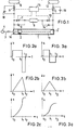
- Figur 1 eine schematische Darstellung, anhand der das Prinzip erläutert wird,
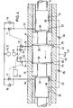
Figuren 2 und 3 Diagramme über Bewegungsabläufe, die mit Hilfe des erfindungsgemäßen Verfahrens bewirkt werden können, undFigur 4 ein spezielles Ausführungsbeispiel für einen für die Durchführung des erfindungsgemäßen Steuerungsverfahrens geeigneten hydraulischen Antrieb.
- FIG. 1 shows a schematic illustration, on the basis of which the principle is explained,
- Figures 2 and 3 diagrams of motion sequences that can be effected with the aid of the method according to the invention, and
- Figure 4 shows a special embodiment for a hydraulic drive suitable for performing the control method according to the invention.
Bei der Prinzip-Darstellung nach Figur 1 sind der Hydraulikzylinder mit 1, der darin verschiebbar angeordnete Hydraulikkolben mit 2 und die über eine Kolbenstange 3 mit dem Kolben 2 verbundene Stellmasse mit 4 bezeichnet. 4 kann z. B. das Verschlußglied eines Schiebers oder eines Ventiles sein. Die linke Seite des Zylinders 1 ist über ein Ventil 5 mit einem Hochdruckspeicher 6 und über ein Ventil 7 mit dem Niederdruckspeicher 8 verbunden. Das Ventil 7 ist mittels eines Rückschlagventils 9 überbrückt., das derart eingebaut ist, daß der Druck des Speichers 6 nicht im Niederdruckspeicher 8 auftritt.In the basic illustration according to FIG. 1, the hydraulic cylinder is denoted by 1, the hydraulic piston displaceably arranged therein by 2 and the actuating mass connected by a
In entsprechender Weise ist die rechte Seite des Zylinders 1 über ein Ventil 11 mit einem weiteren Hochdruckspeicher 12 und über das Ventil 13 mit dem Niederdruckspeicher 8 verbunden. Das das Ventil 13 überbrückende Rückschlagventil ist mit 14 bezeichnet. Die Ventile 5, 7, 11 und 13 sind automatisch betätigbar, und zwar mit Hilfe des als Block dargestellten Steuergerätes 15. Parallel zu den Ventilen 5 und 11 sind schließlich noch die in Richtung zu den jeweiligen Hochdruckspeichern 6 bzw. 12 zu öffnenden Rückschlagventile 18 und 19 vorgesehen.In a corresponding manner, the right side of the cylinder 1 is connected to a further high-
Die Bewegung des Kolbens 2 mit der Masse 4 aus seiner linken Endlage in seine rechte Endlage geschieht folgendermaßen: Von den zunächst geschlossenen Ventilen werden zur Zeit t0 das Ventil 5 zum Hochdruckspeicher 6 und das Ventil 13 zum Niederdruckspeicher 8 geöffnet. Dadurch erhöht sich der Druck im links vom Kolben 2 gelegenen Zylinderraum 16, so daß der Kolben 2 mit der Masse 4 nach rechts beschleunigt wird. Die im rechts vom Kolben 2 gelegenen Zylinderraum 17 befindliche Hydraulikflüssigkeit strömt über das Ventil 13 in den Niederdruckspeicher ab. Durch das Rückschlagventil 9 sind der Hochdruckspeicher 6 und der Niederdruckspeicher 8 voneinander getrennt. Während der Bewegung des Kolbens 2 mit der Masse 4 von links nach rechts wird zum Zeitpunkt t1 eine Umsteuerung des Druckes vorgenommen, und zwar derart, daß die Beschleunigungsphase beendet und die Verzögerungsphase begonnen wird. Dazu werden zum-Zeitpunkt t1 die Ventile 5 und 13 geschlossen. Der Zylinderteilraum 16 wird dadurch druckentlastet. Das infolge der Weiterbewegung des Kolbens 2 im Raum 17 verdrängte Ölvolumen fließt über das Rückschlagventil 19 in den Hochdruckspeicher 12. Der dadurch erzeugte Hochdruck im Zylinderraum 17 bewirkt die gewünschte Verzögerung des Kolbens 2 mit der Masse 4. Infolge des Rückschlagventils 9 ist sichergestellt, daß im Teilraum 16 keine störenden Kavitationen auftreten. Über das Rückschlagventil 9 füllt sich der Teilraum 16 mit Hydraulikflüssigkeit aus dem Niederdruckspeicher 8. Zum Zeitpunkt t2 gelangt der Kolben 2 in seine rechte Endlage (gestrichelt dargestellt und mit 2' bezeichnet). In entsprechender Weise kann eine Bewegung des Kolbens 2 von rechts nach links bewirkt werden. Dazu werden zunächst die Ventile 11 und 7 geöffnet, wodurch die Beschleunigungsphase beginnt. Durch Schließen dieser beiden Ventile und Öffnung des Ventils 13 wird die Verzögerungsphase eingeleitet.The movement of the
Der übergang von der Beschleunigungsphase zur Verzögerungsphase kann prinzipiell zu einem beliebigen Zeitpunkt zwischen to und t2 erfolgen. In den Figuren 2a bis 2c sind Diagramme dargestellt, die zu einem Bewegungsablauf gehören, bei dem während 75 % der gesamten Stellzeit beschleunigt und während der restlichen 25 % verzögert wird. Figur 2a stellt den Beschleunigungswert in Abhängigkeit von der Zeit dar. Daraus geht hervor, daß in einem solchen Fall die Verzögerung (negative Beschleunigung) wesentlich größer gewählt werden muß als die Beschleunigung, damit in der nur 25 % des gesamten Bewegungsablaufs betragenden Zeit die notwendige Verzögerung des Kolbens 2 mit der Masse 4 erreicht werden kann. Für die Praxis bedeutet das, daß der Druck im Speicher 12 entsprechend höher gewählt werden muß. Figur 2b zeigt die Geschwindigkeit v eines solchen Bewegungsablaufs in Abhängigkeit von der Zeit.Figur 2c zeigt entsprechend den vom Kolben 2 zurückgelegten Weg s in Abhängigkeit von der Zeit.In principle, the transition from the acceleration phase to the deceleration phase can take place at any time between t o and t 2 . FIGS. 2a to 2c show diagrams which belong to a movement sequence in which acceleration takes place during 75% of the total actuating time and is decelerated during the remaining 25%. Figure 2a shows the acceleration value as a function of time. From this it can be seen that in such a case the deceleration (negative acceleration) must be selected to be significantly greater than the acceleration, so that the necessary deceleration in the time, which is only 25% of the total movement sequence of the
In den Diagrammen nach den Figuren 3a bis 3c ist ein Bewegungsablauf dargestellt, bei dem die Druckumsteuerung auf halbem Weg des Kolbens 2 bzw. nach der halben Zeit des gesamten Bewegungsablaufs vorgenommen wird. In einem solchen Fall können Beschleunigungs- und Verzögerungswert gleich gewählt werden. Für die Praxis bedeutet das, daß der Druck in den Speichern 6 und 12 gleich sein kann oder nur ein Hochdruckspeicher erforderlich ist. Geschwindigkeit und Weg s in Abhängigkeit von der Zeit sind für einen solchen Fall in Figur 3b und Figur 3c dargestellt. Der Vorteil eines in dieser Weise ablaufenden Stellvorganges liegt darin, daß - wegen der Symmetrie der Kurven - die Bewegungen in beiden Richtungen gleichförmig ablaufen, was bei Bewegungsabläufen nach den Figuren 2a bis 2c nicht der Fall ist. Voraussetzung für einen gleichförmig ablaufenden Bewegungsvorgang sind noch gleich große Wirkflächen. Beim Gegenstand der Figur 1 kann das z. B. dadurch erreicht werden, daß der Kolben -2 auch auf seiner rechten Seite mit einer Kolbenstange ausgerüstet ist.The diagrams according to FIGS. 3a to 3c show a sequence of movements in which the pressure reversal is carried out half way of the
Die Betätigung von Steuerventilen zur Umsteuerung der Drücke während der Kolbenbewegung kann zu Nachteilen führen, wenn ein Steuerventil z. B. durch Schwergängigkeit nicht im richtigen Zeitpunkt schaltet. Dies läßt sich vermeiden, wenn die ölströme sich wegeabhängig selbst steuern, wie dies beispielsweise in Figur 4 gezeigt wird. Bei diesem Ausführungsbeispiel sind die Abschnitte 20 und 21 der beidseitig am Kolben 2 befestigten Kolbenstange 3 als Steuerkolben ausgebildet.The actuation of control valves for reversing the pressures during the piston movement can lead to disadvantages if a control valve z. B. does not switch at the right time due to binding. This can be avoided if the oil flows control themselves depending on the path, as is shown, for example, in FIG. In this exemplary embodiment, the
Die Öl-Zu- und -Abfuhrkanäle werden durch Bohrungen 31 und 32 im Zylindermantel gebildet; sie können an der Zylinderinnenwand zu Ringkanälen bzw. Steuernuten 22, 23, 24, 25 erweitert sein. Diese Steuernuten korrespondieren mit abgeschrägten Steuerkanten 27, 28, 29, 30 am Kolben und an der Kolbenstange.The oil supply and discharge channels are formed by
Soll beispielsweise der (in seiner Mittelstellung dargestellte) Kolben 2 in der gezeichneten Pfeilrichtung von seiner rechten Endstellung nach links laufen, so werden zum Start vom Steuerorgan 15 Ventil 11 und 13 geöffnet; Ventile 5 und 7 bleiben geschlossen. Aus dem Hochdruckspeicher 6 fließt das Drucköl über Ventil 11, Leitung 32 in den Ringkanal 23 und weiter in den Zylinderraum 17. Das aus dem Zylinderraum 16 zu verdrängende Öl fließt über den Ringkanal 24 in die Leitung 31 und über das Rückschlagventil 33 in den Niederdruckspeicher 8. Im (dargestellten) Umsteuerzeitpunkt schließt die Steuerkante 28 des Steuerkolbens 21 den Ringkanal 23; damit ist der Hochdruck- Ölzufluß abgesperrt. Zum Nachfüllen des Zylinderraums 17 öffnet nun die Steuerkante 30 des Kolbens 2 den Ringkanal 25, der über das schon geöffnete Ventil 13 mit dem Niederdruckspeicher 8 in Verbindung steht. Im Zylinderraum 16 wird gleichzeitig durch die Steuerkante 29 des Kolbens 2 der bisherige Ölabfluß über Ringkanal 24 und Rückschlagventil 33 in den Niederdruckspeicher 8 unterbrochen und durch die Steuerkante 27 des Steuerkolbens 20 der Ringkanal 22 geöffnet, so daß das zu verdrängende Öl über Rückschlagventil 18 in den Hochdruckspeicher 6 gefördert werden muß. Nunmehr herrscht im Zylinderraum 16 der gewünschte Verzögerungsdruck, während im Ringraum 17 nur der zum Nachfüllen nötige Druck des Niederdruckspeichers 8 wirkt.If, for example, the piston 2 (shown in its central position) is to run from its right end position to the left in the direction of the arrow, 15
Gegen Hubende kann die zu verzögernde Energie so weit aufgebraucht sein, daß das Rückschlagventil 18 nicht mehr überwunden werden kann. Zu diesem Zweck ist ein Leitungssystem 26 mit einstellbaren Drosseln 35 und 36 vorgesehen, das in Höhe der Steuerkolben 20 und 21 mündet und mit einem Speichertank 37 in Verbindung steht. Die Lage der MÜndungen 38 und 39 ist so gewählt, daß sie vom zugehörigen Steuerkolben nur dann freigegeben werden, kurz bevor dieser seine eine Endstellung (der linke Steuerkolben seine linke Endstellung und der rechte Kolben seine rechte Endstellung) erreicht. In der jeweiligen Endphase der Bewegungen des Steuerkolbens wird dann eine geringe ölmenge über das Leitungssystem 26 und über die jeweils zugehörige Drossel in den Speichertank 37 abgeführt.Towards the end of the stroke, the energy to be decelerated can be used up to such an extent that the
Gegenüber dem Ausführungsbeispiel nach Figur 1 sind beim Ausführungsbeispiel nach Figur 4 die die Ventile 7 und 13 überbrückenden Rückschlagventile 9 bzw. 33 und 14 bzw. 34 in umgekehrter Richtung angeordnet. Der Grund dafür liegt darin, daß die Rückschlagventile beim Gegenstand der Figur 1 die Aufgabe erfüllen, den Niederdruckspeicher vom Hochdruckspeicher ständig getrennt zu halten. Beim Gegenstand der Figur 4 ist diese Aufgabe bereits durch die besondere Lage der Steuerkanten und -kanäle erfüllt. Die Ventile 7 und 13könnten entfallen, wenn nachzufüllendes Öl aus dem Speichertank 37 ersetzt würde. Das ist möglich, wenn die Bewegung des Kolbens nicht allzu schnell erfolgen soll. Anderenfalls ist ein bestimmter Nachfülldruck (Druck des Niederdruckspeichers) erforderlich. Ein zweckmäßiger Druck im Hochdruckspeicher ist 200 bar. Bei schnellen Bewegungen ist der Druck im Niederdruckspeicher zweckmäßigerweise 20 bar.Compared to the exemplary embodiment according to FIG. 1, in the exemplary embodiment according to FIG. 4, the
Claims (18)
Applications Claiming Priority (2)
| Application Number | Priority Date | Filing Date | Title |
|---|---|---|---|
| DE3044675 | 1980-11-27 | ||
| DE19803044675 DE3044675A1 (en) | 1980-11-27 | 1980-11-27 | METHOD FOR CONTROLLING A HYDRAULIC DRIVE AND HYDRAULIC DRIVE SUITABLE FOR CARRYING OUT THIS CONTROL METHOD |
Publications (3)
| Publication Number | Publication Date |
|---|---|
| EP0053370A2 true EP0053370A2 (en) | 1982-06-09 |
| EP0053370A3 EP0053370A3 (en) | 1983-05-04 |
| EP0053370B1 EP0053370B1 (en) | 1986-10-15 |
Family
ID=6117710
Family Applications (1)
| Application Number | Title | Priority Date | Filing Date |
|---|---|---|---|
| EP81109942A Expired EP0053370B1 (en) | 1980-11-27 | 1981-11-27 | Method to control a hydraulic mechanism, and hydraulic mechanism suited to carry out said method |
Country Status (2)
| Country | Link |
|---|---|
| EP (1) | EP0053370B1 (en) |
| DE (1) | DE3044675A1 (en) |
Cited By (5)
| Publication number | Priority date | Publication date | Assignee | Title |
|---|---|---|---|---|
| FR2522080A1 (en) * | 1982-02-20 | 1983-08-26 | Hartmann & Laemmle | TRAINING FOR A MOBILE MASS USING A HYDRAULIC ENGINE |
| EP0116024A1 (en) * | 1983-02-03 | 1984-08-15 | Göran Palmers | An energy recovery device in hydraulically driven machines |
| EP0225397A1 (en) * | 1985-12-13 | 1987-06-16 | Carl Schenck Ag | Method and apparatus for producing intermittent loading of a specimen |
| EP0710774A3 (en) * | 1994-11-07 | 1998-07-29 | FESTO AG & Co | Power cylinder |
| CN111336291A (en) * | 2018-12-19 | 2020-06-26 | 株式会社斗山 | Reverse rotation preventing valve of rotary motor for engineering equipment |
Families Citing this family (1)
| Publication number | Priority date | Publication date | Assignee | Title |
|---|---|---|---|---|
| DE102014212129A1 (en) * | 2014-06-25 | 2015-12-31 | Robert Bosch Gmbh | Hydraulic arrangement |
Family Cites Families (13)
| Publication number | Priority date | Publication date | Assignee | Title |
|---|---|---|---|---|
| DE1263514B (en) * | 1961-07-27 | 1968-03-14 | Siemens Ag | Hydraulic drive |
| US3396635A (en) * | 1966-11-30 | 1968-08-13 | Cessna Aircraft Co | Cushion stop for hydraulic actuators |
| FR1563208A (en) * | 1968-03-01 | 1969-04-11 | ||
| CH473319A (en) * | 1968-06-19 | 1969-05-31 | Hydrel Ag Maschf | Fully hydraulic device on the machine or apparatus with a straight back and forth moving part, for largely load and speed independent reversal of the accuracy of the movement of the part between two adjustable reversing points |
| US3563273A (en) * | 1968-10-28 | 1971-02-16 | Carl R Mills | Actuator valve |
| FR2129156A5 (en) * | 1971-03-17 | 1972-10-27 | Citroen Sa | |
| DE2245129A1 (en) * | 1972-09-14 | 1974-03-21 | Bosch Gmbh Robert | WORK CYLINDER |
| NL7214004A (en) * | 1972-10-17 | 1974-04-19 | ||
| CH568495A5 (en) * | 1974-03-11 | 1975-10-31 | Haeny & Cie Ag | |
| NL182162C (en) * | 1977-01-10 | 1988-01-18 | Hydraudyne Bv | DEVICE FOR HYDRAULIC OR PNEUMATIC DRIVING AND BRAKING OF A TOOL. |
| DE2821489C3 (en) * | 1978-05-17 | 1981-03-19 | Danfoss A/S, 6430 Nordborg | Valve arrangement with two valve parts sliding one on top of the other |
| GB2035464B (en) * | 1978-11-28 | 1982-12-15 | Dartec Ltd | Actuator protection assemblies |
| DE2851478A1 (en) * | 1978-11-28 | 1980-06-04 | Mts Systems Gmbh | Quick-action HV switching mechanism - has two energy stores connected via holes to chamber containing drive piston |
-
1980
- 1980-11-27 DE DE19803044675 patent/DE3044675A1/en not_active Withdrawn
-
1981
- 1981-11-27 EP EP81109942A patent/EP0053370B1/en not_active Expired
Cited By (7)
| Publication number | Priority date | Publication date | Assignee | Title |
|---|---|---|---|---|
| FR2522080A1 (en) * | 1982-02-20 | 1983-08-26 | Hartmann & Laemmle | TRAINING FOR A MOBILE MASS USING A HYDRAULIC ENGINE |
| EP0116024A1 (en) * | 1983-02-03 | 1984-08-15 | Göran Palmers | An energy recovery device in hydraulically driven machines |
| US4707988A (en) * | 1983-02-03 | 1987-11-24 | Palmers Goeran | Device in hydraulically driven machines |
| EP0225397A1 (en) * | 1985-12-13 | 1987-06-16 | Carl Schenck Ag | Method and apparatus for producing intermittent loading of a specimen |
| EP0710774A3 (en) * | 1994-11-07 | 1998-07-29 | FESTO AG & Co | Power cylinder |
| CN111336291A (en) * | 2018-12-19 | 2020-06-26 | 株式会社斗山 | Reverse rotation preventing valve of rotary motor for engineering equipment |
| CN111336291B (en) * | 2018-12-19 | 2022-03-29 | 股份公司摩拓乐 | Reverse rotation preventing valve of rotary motor for engineering equipment |
Also Published As
| Publication number | Publication date |
|---|---|
| EP0053370A3 (en) | 1983-05-04 |
| EP0053370B1 (en) | 1986-10-15 |
| DE3044675A1 (en) | 1982-07-08 |
Similar Documents
| Publication | Publication Date | Title |
|---|---|---|
| DE3323363C2 (en) | ||
| DE2516810C3 (en) | Impact device operated with hydraulic fluid | |
| DE2512480C3 (en) | Valve device for a hydraulically operated electrical circuit breaker | |
| DE1916266A1 (en) | Electrohydraulic actuator | |
| DE2021182A1 (en) | Device for setting the different plunger speeds and pressures required during die casting in casting machines, in particular cold chamber die casting machines | |
| EP0053370A2 (en) | Method to control a hydraulic mechanism, and hydraulic mechanism suited to carry out said method | |
| EP0641699B1 (en) | Pneumatic braking installation | |
| DE3911495C1 (en) | Hydraulic valve actuation unit for piston engines | |
| DE2003584A1 (en) | Device for pressure medium distribution | |
| DE10138881A1 (en) | Method for operating an electro-hydraulic valve control of an internal combustion engine, computer program and control and regulating device for operating an internal combustion engine | |
| DE2447964B2 (en) | Method and device for die casting with a horizontal cold chamber machine | |
| DE855270C (en) | Air brakes, especially for railways | |
| DE69420713T2 (en) | DEVICE DRIVEN BY PRESSURE MEANS A LINEAR MOVEMENT | |
| DE3041788C2 (en) | Drive device for the slide gate of a metallurgical vessel | |
| DE2051855A1 (en) | Automatic damping valve | |
| DE856393C (en) | Piston slide control for central lubrication systems | |
| DE955324C (en) | Single air brake for rail vehicles with a two-pressure control valve | |
| DE2463062C3 (en) | Shot valve for die casting with a horizontal cold chamber machine | |
| DE256577C (en) | ||
| DE3104286C2 (en) | ||
| AT138795B (en) | Driver valve for air brakes. | |
| DE816409C (en) | Compressed air brake with two- and three-pressure control valve as well as with contact and locking cylinder | |
| EP0152937B1 (en) | Hydraulic drive element for weaving shuttles | |
| DE2708512A1 (en) | Double acting cylinder hydraulic rammer - can automatically vary stroke length to compensate for pressure variation | |
| DE3344051C2 (en) |
Legal Events
| Date | Code | Title | Description |
|---|---|---|---|
| PUAI | Public reference made under article 153(3) epc to a published international application that has entered the european phase |
Free format text: ORIGINAL CODE: 0009012 |
|
| 17P | Request for examination filed |
Effective date: 19811208 |
|
| AK | Designated contracting states |
Designated state(s): CH FR GB IT |
|
| PUAL | Search report despatched |
Free format text: ORIGINAL CODE: 0009013 |
|
| AK | Designated contracting states |
Designated state(s): CH FR GB IT LI |
|
| ITF | It: translation for a ep patent filed | ||
| GRAA | (expected) grant |
Free format text: ORIGINAL CODE: 0009210 |
|
| AK | Designated contracting states |
Kind code of ref document: B1 Designated state(s): CH FR GB IT LI |
|
| ET | Fr: translation filed | ||
| PLBE | No opposition filed within time limit |
Free format text: ORIGINAL CODE: 0009261 |
|
| STAA | Information on the status of an ep patent application or granted ep patent |
Free format text: STATUS: NO OPPOSITION FILED WITHIN TIME LIMIT |
|
| 26N | No opposition filed | ||
| PG25 | Lapsed in a contracting state [announced via postgrant information from national office to epo] |
Ref country code: GB Effective date: 19881127 |
|
| PG25 | Lapsed in a contracting state [announced via postgrant information from national office to epo] |
Ref country code: LI Effective date: 19881130 Ref country code: CH Effective date: 19881130 |
|
| GBPC | Gb: european patent ceased through non-payment of renewal fee | ||
| PG25 | Lapsed in a contracting state [announced via postgrant information from national office to epo] |
Ref country code: FR Free format text: LAPSE BECAUSE OF NON-PAYMENT OF DUE FEES Effective date: 19890731 |
|
| REG | Reference to a national code |
Ref country code: CH Ref legal event code: PL |
|
| REG | Reference to a national code |
Ref country code: FR Ref legal event code: ST |
|
| ITTA | It: last paid annual fee |