EP0053370B1 - Procédé pour le contrôle d'un mécanisme hydraulique et mécanisme hydraulique pour pratiquer ce procédé - Google Patents
Procédé pour le contrôle d'un mécanisme hydraulique et mécanisme hydraulique pour pratiquer ce procédé Download PDFInfo
- Publication number
- EP0053370B1 EP0053370B1 EP81109942A EP81109942A EP0053370B1 EP 0053370 B1 EP0053370 B1 EP 0053370B1 EP 81109942 A EP81109942 A EP 81109942A EP 81109942 A EP81109942 A EP 81109942A EP 0053370 B1 EP0053370 B1 EP 0053370B1
- Authority
- EP
- European Patent Office
- Prior art keywords
- piston
- hydraulic
- pressure
- low
- pressure accumulator
- Prior art date
- Legal status (The legal status is an assumption and is not a legal conclusion. Google has not performed a legal analysis and makes no representation as to the accuracy of the status listed.)
- Expired
Links
- 238000000034 method Methods 0.000 title claims description 15
- 230000001133 acceleration Effects 0.000 claims description 13
- 239000012530 fluid Substances 0.000 claims description 6
- 230000007704 transition Effects 0.000 claims description 2
- 230000003467 diminishing effect Effects 0.000 claims 2
- 230000000694 effects Effects 0.000 claims 1
- 238000010586 diagram Methods 0.000 description 2
- 230000003247 decreasing effect Effects 0.000 description 1
- 238000001514 detection method Methods 0.000 description 1
- 238000005265 energy consumption Methods 0.000 description 1
Images

Classifications
-
- F—MECHANICAL ENGINEERING; LIGHTING; HEATING; WEAPONS; BLASTING
- F15—FLUID-PRESSURE ACTUATORS; HYDRAULICS OR PNEUMATICS IN GENERAL
- F15B—SYSTEMS ACTING BY MEANS OF FLUIDS IN GENERAL; FLUID-PRESSURE ACTUATORS, e.g. SERVOMOTORS; DETAILS OF FLUID-PRESSURE SYSTEMS, NOT OTHERWISE PROVIDED FOR
- F15B11/00—Servomotor systems without provision for follow-up action; Circuits therefor
- F15B11/02—Systems essentially incorporating special features for controlling the speed or actuating force of an output member
- F15B11/04—Systems essentially incorporating special features for controlling the speed or actuating force of an output member for controlling the speed
- F15B11/046—Systems essentially incorporating special features for controlling the speed or actuating force of an output member for controlling the speed depending on the position of the working member
- F15B11/048—Systems essentially incorporating special features for controlling the speed or actuating force of an output member for controlling the speed depending on the position of the working member with deceleration control
-
- F—MECHANICAL ENGINEERING; LIGHTING; HEATING; WEAPONS; BLASTING
- F15—FLUID-PRESSURE ACTUATORS; HYDRAULICS OR PNEUMATICS IN GENERAL
- F15B—SYSTEMS ACTING BY MEANS OF FLUIDS IN GENERAL; FLUID-PRESSURE ACTUATORS, e.g. SERVOMOTORS; DETAILS OF FLUID-PRESSURE SYSTEMS, NOT OTHERWISE PROVIDED FOR
- F15B2211/00—Circuits for servomotor systems
- F15B2211/20—Fluid pressure source, e.g. accumulator or variable axial piston pump
- F15B2211/21—Systems with pressure sources other than pumps, e.g. with a pyrotechnical charge
- F15B2211/212—Systems with pressure sources other than pumps, e.g. with a pyrotechnical charge the pressure sources being accumulators
-
- F—MECHANICAL ENGINEERING; LIGHTING; HEATING; WEAPONS; BLASTING
- F15—FLUID-PRESSURE ACTUATORS; HYDRAULICS OR PNEUMATICS IN GENERAL
- F15B—SYSTEMS ACTING BY MEANS OF FLUIDS IN GENERAL; FLUID-PRESSURE ACTUATORS, e.g. SERVOMOTORS; DETAILS OF FLUID-PRESSURE SYSTEMS, NOT OTHERWISE PROVIDED FOR
- F15B2211/00—Circuits for servomotor systems
- F15B2211/30—Directional control
- F15B2211/305—Directional control characterised by the type of valves
- F15B2211/3056—Assemblies of multiple valves
-
- F—MECHANICAL ENGINEERING; LIGHTING; HEATING; WEAPONS; BLASTING
- F15—FLUID-PRESSURE ACTUATORS; HYDRAULICS OR PNEUMATICS IN GENERAL
- F15B—SYSTEMS ACTING BY MEANS OF FLUIDS IN GENERAL; FLUID-PRESSURE ACTUATORS, e.g. SERVOMOTORS; DETAILS OF FLUID-PRESSURE SYSTEMS, NOT OTHERWISE PROVIDED FOR
- F15B2211/00—Circuits for servomotor systems
- F15B2211/30—Directional control
- F15B2211/315—Directional control characterised by the connections of the valve or valves in the circuit
- F15B2211/31523—Directional control characterised by the connections of the valve or valves in the circuit being connected to a pressure source and an output member
- F15B2211/31535—Directional control characterised by the connections of the valve or valves in the circuit being connected to a pressure source and an output member having multiple pressure sources and a single output member
-
- F—MECHANICAL ENGINEERING; LIGHTING; HEATING; WEAPONS; BLASTING
- F15—FLUID-PRESSURE ACTUATORS; HYDRAULICS OR PNEUMATICS IN GENERAL
- F15B—SYSTEMS ACTING BY MEANS OF FLUIDS IN GENERAL; FLUID-PRESSURE ACTUATORS, e.g. SERVOMOTORS; DETAILS OF FLUID-PRESSURE SYSTEMS, NOT OTHERWISE PROVIDED FOR
- F15B2211/00—Circuits for servomotor systems
- F15B2211/30—Directional control
- F15B2211/32—Directional control characterised by the type of actuation
- F15B2211/327—Directional control characterised by the type of actuation electrically or electronically
-
- F—MECHANICAL ENGINEERING; LIGHTING; HEATING; WEAPONS; BLASTING
- F15—FLUID-PRESSURE ACTUATORS; HYDRAULICS OR PNEUMATICS IN GENERAL
- F15B—SYSTEMS ACTING BY MEANS OF FLUIDS IN GENERAL; FLUID-PRESSURE ACTUATORS, e.g. SERVOMOTORS; DETAILS OF FLUID-PRESSURE SYSTEMS, NOT OTHERWISE PROVIDED FOR
- F15B2211/00—Circuits for servomotor systems
- F15B2211/40—Flow control
- F15B2211/405—Flow control characterised by the type of flow control means or valve
- F15B2211/40576—Assemblies of multiple valves
- F15B2211/40584—Assemblies of multiple valves the flow control means arranged in parallel with a check valve
-
- F—MECHANICAL ENGINEERING; LIGHTING; HEATING; WEAPONS; BLASTING
- F15—FLUID-PRESSURE ACTUATORS; HYDRAULICS OR PNEUMATICS IN GENERAL
- F15B—SYSTEMS ACTING BY MEANS OF FLUIDS IN GENERAL; FLUID-PRESSURE ACTUATORS, e.g. SERVOMOTORS; DETAILS OF FLUID-PRESSURE SYSTEMS, NOT OTHERWISE PROVIDED FOR
- F15B2211/00—Circuits for servomotor systems
- F15B2211/40—Flow control
- F15B2211/415—Flow control characterised by the connections of the flow control means in the circuit
- F15B2211/41581—Flow control characterised by the connections of the flow control means in the circuit being connected to an output member and a return line
-
- F—MECHANICAL ENGINEERING; LIGHTING; HEATING; WEAPONS; BLASTING
- F15—FLUID-PRESSURE ACTUATORS; HYDRAULICS OR PNEUMATICS IN GENERAL
- F15B—SYSTEMS ACTING BY MEANS OF FLUIDS IN GENERAL; FLUID-PRESSURE ACTUATORS, e.g. SERVOMOTORS; DETAILS OF FLUID-PRESSURE SYSTEMS, NOT OTHERWISE PROVIDED FOR
- F15B2211/00—Circuits for servomotor systems
- F15B2211/40—Flow control
- F15B2211/42—Flow control characterised by the type of actuation
- F15B2211/426—Flow control characterised by the type of actuation electrically or electronically
-
- F—MECHANICAL ENGINEERING; LIGHTING; HEATING; WEAPONS; BLASTING
- F15—FLUID-PRESSURE ACTUATORS; HYDRAULICS OR PNEUMATICS IN GENERAL
- F15B—SYSTEMS ACTING BY MEANS OF FLUIDS IN GENERAL; FLUID-PRESSURE ACTUATORS, e.g. SERVOMOTORS; DETAILS OF FLUID-PRESSURE SYSTEMS, NOT OTHERWISE PROVIDED FOR
- F15B2211/00—Circuits for servomotor systems
- F15B2211/40—Flow control
- F15B2211/46—Control of flow in the return line, i.e. meter-out control
-
- F—MECHANICAL ENGINEERING; LIGHTING; HEATING; WEAPONS; BLASTING
- F15—FLUID-PRESSURE ACTUATORS; HYDRAULICS OR PNEUMATICS IN GENERAL
- F15B—SYSTEMS ACTING BY MEANS OF FLUIDS IN GENERAL; FLUID-PRESSURE ACTUATORS, e.g. SERVOMOTORS; DETAILS OF FLUID-PRESSURE SYSTEMS, NOT OTHERWISE PROVIDED FOR
- F15B2211/00—Circuits for servomotor systems
- F15B2211/60—Circuit components or control therefor
- F15B2211/625—Accumulators
-
- F—MECHANICAL ENGINEERING; LIGHTING; HEATING; WEAPONS; BLASTING
- F15—FLUID-PRESSURE ACTUATORS; HYDRAULICS OR PNEUMATICS IN GENERAL
- F15B—SYSTEMS ACTING BY MEANS OF FLUIDS IN GENERAL; FLUID-PRESSURE ACTUATORS, e.g. SERVOMOTORS; DETAILS OF FLUID-PRESSURE SYSTEMS, NOT OTHERWISE PROVIDED FOR
- F15B2211/00—Circuits for servomotor systems
- F15B2211/60—Circuit components or control therefor
- F15B2211/665—Methods of control using electronic components
- F15B2211/6654—Flow rate control
-
- F—MECHANICAL ENGINEERING; LIGHTING; HEATING; WEAPONS; BLASTING
- F15—FLUID-PRESSURE ACTUATORS; HYDRAULICS OR PNEUMATICS IN GENERAL
- F15B—SYSTEMS ACTING BY MEANS OF FLUIDS IN GENERAL; FLUID-PRESSURE ACTUATORS, e.g. SERVOMOTORS; DETAILS OF FLUID-PRESSURE SYSTEMS, NOT OTHERWISE PROVIDED FOR
- F15B2211/00—Circuits for servomotor systems
- F15B2211/70—Output members, e.g. hydraulic motors or cylinders or control therefor
- F15B2211/755—Control of acceleration or deceleration of the output member
Definitions
- the invention relates to a method for controlling a hydraulic actuator with a hydraulic cylinder, a hydraulic piston, a high-pressure source and a low-pressure accumulator for the pressure medium and with lines opening into the hydraulic cylinder for connecting the cylinder space sections separated from the piston to the high-pressure source or the low-pressure accumulator which during a first phase of movement of the piston from its one end position to its other, the enlarging space section of the hydraulic cylinder is connected to the high pressure source to accelerate the piston, while the shrinking space section is connected to the low pressure accumulator, and during a second Movement phase of the piston, the enlarging cylinder chamber is connected to the low-pressure accumulator and a braking of the piston by an increase in pressure in the decreasing cylinder chamber section by interrupting the connection m it is caused by the low pressure accumulator.
- a control method of this type is known from DE-B-16 50 330.
- the speed of the piston during its movement from one end position to the other is essentially uniform and is determined or limited by the amount of pressure medium delivered or by two throttles, one of which is arranged in the pressure medium supply line and one in the pressure medium discharge line.
- the end position is braked by shutting off the unhindered pressure medium outflow from the reducing space shortly before the end of the piston movement.
- the present invention is based on the object of proposing a control method of the type mentioned at the outset, in which the pressure of the pressure medium becomes fully effective unhindered by throttles in order to achieve the fastest possible sequence of the actuating process.
- this object is achieved in that the deceleration phase immediately follows the acceleration phase, that the reversal takes place for the purpose of the transition from the acceleration phase to the deceleration phase at a time in which the piston has traveled about half its way and that for reversing the acceleration phase into the deceleration phase the pressure medium supply from the pressure medium source to the enlarging cylinder chamber section is blocked, and that during the deceleration phase pressure medium is displaced from the shrinking cylinder chamber section due to the inertia of the masses to be braked into a high-pressure accumulator.
- the pressure of the pressure medium is effective unhindered during the acceleration phase, so that an optimal acceleration of the piston with its actuating mass can be achieved.
- the deceleration phase begins, in that a connection is established between the space that is shrinking and the high-pressure source designed as a high-pressure accumulator.
- the pressure of the high-pressure accumulator is thus also used for braking, so that the acceleration force is equal to the deceleration force.
- the hydraulic cylinder is denoted by 1, the hydraulic piston displaceably arranged therein by 2 and the actuating mass connected by a piston rod 3 to the piston 2 by 4.
- 4 can e.g. B. the closure member of a slide or a valve.
- the left side of the cylinder 1 is connected to a high-pressure accumulator 6 via a valve 5 and to the low-pressure accumulator 8 via a valve 7.
- the valve 7 is bridged by a check valve 9, which is installed in such a way that the pressure of the accumulator 6 does not occur in the low-pressure accumulator 8.
- the right side of the cylinder 1 is connected to a further high-pressure accumulator 12 via a valve 11 and to the low-pressure accumulator 8 via the valve 13.
- the check valve bridging the valve 13 is designated by 14.
- the Valves 5, 7, 11 and 13 can be actuated automatically, with the aid of the control unit 15 shown as a block.
- the check valves 18 and 19 which can be opened in the direction of the respective high-pressure accumulators 6 and 12 intended.
- the movement of the piston 2 with the mass 4 from its left end position into its right end position takes place as follows: from the initially closed valves, the valve 5 to the high-pressure accumulator 6 and the valve 13 to the low-pressure accumulator 8 are opened at the time t o . This increases the pressure in the cylinder space 16 to the left of the piston 2, so that the piston 2 is accelerated with the mass 4 to the right.
- the hydraulic fluid located in the cylinder chamber 17 to the right of the piston 2 flows through the valve 13 into the low-pressure accumulator.
- the high-pressure accumulator 6 and the low-pressure accumulator 8 are separated from one another by the check valve 9.
- the piston 2 reaches its right-hand end position (shown in broken lines and denoted by 2 '). In a corresponding manner, the piston 2 can be moved from right to left.
- the valves 11 and 7 are first opened, whereby the acceleration phase begins.
- the delay phase is initiated by closing these two valves and opening valve 13.
- FIGS. 2a to 2c show a movement sequence in which the pressure reversal is carried out half way of the piston 2 or after half the time of the entire movement sequence. In such a case, the acceleration and deceleration values can be chosen to be the same. In practice, this means that the pressure in the accumulators 6 and 12 can be the same or only a high-pressure accumulator is required.
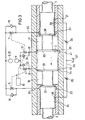
- control valves for reversing the pressures during the piston movement can lead to disadvantages if a control valve z. B. does not switch at the right time due to stiffness. This can be avoided if the oil flows control themselves depending on the path, as is shown, for example, in FIG. 3.
- the sections 20 and 21 of the piston rod 3 fastened on both sides to the piston 2 are designed as control pistons.
- the oil supply and discharge channels are formed by bores 31 and 32 in the cylinder jacket; they can be expanded on the cylinder inner wall to form ring channels or control grooves 22, 23, 24, 25. These control grooves correspond to chamfered control edges 27, 28, 29, 30 on the piston and on sections 20 and 21 of the piston rod.
- valves 11 and 13 are opened at the start by the control member; Valves 5 and 7 remain closed.
- the pressure oil flows from the high-pressure accumulator 6 via valve 11, line 32 into the annular channel 23 and further into the cylinder space 17.
- the oil to be displaced from the cylinder space 16 flows via the annular channel 24 into the line 31 and via the check valve 33 into the low-pressure accumulator 8
- the control edge 28 of the control piston 21 closes the ring channel 23; the high-pressure oil inflow is shut off.
- the control edge 30 of the piston 2 now opens the annular channel 25, which is connected to the low-pressure accumulator 8 via the already opened valve 13.
- the previous oil flow via ring channel 24 and check valve 33 into the low-pressure accumulator 8 is interrupted by the control edge 29 of the piston 2 and the ring channel 22 is opened by the control edge 27 of the control piston 20, so that the oil to be displaced via check valve 18 in the High-pressure accumulator 6 must be promoted.
- the desired deceleration pressure now prevails in the cylinder space 16, while only the pressure of the low-pressure accumulator 8 required for refilling acts in the annular space 17.
- a line system 26 with adjustable throttles 35 and 36 is provided, which in the amount of Control piston 20 and 21 opens and communicates with a storage tank 37.
- the position of the orifices 38 and 39 is selected so that they are only released by the associated control piston shortly before it reaches its one end position (the left control piston has its left end position and the right piston has its right end position).
- a small amount of oil is then discharged into the storage tank 37 via the line system 26 and via the associated throttle, as a result of which the piston safely reaches its end position.
- the check valves 33 and 34 bridging the valves 7 and 13 are arranged in the opposite direction to the check valves 9 and 13.
- the check valves in the object of FIG. 1 fulfill the task of keeping the low-pressure accumulator constantly separate from the high-pressure accumulator.
- this task is already fulfilled by the special position of the control edges and channels.
- the valves 7 and 13 could be omitted if oil to be refilled from the storage tank 37 were replaced. This is possible if the storage tank 37 is operated at atmospheric pressure and the control grooves 24, 25 are connected to the storage tank 37 (indicated by the lines 40 and 41 shown in broken lines).
- a certain refill pressure pressure of the low-pressure accumulator
- a suitable pressure in the high-pressure accumulator is 200 bar.
- the pressure in the low-pressure accumulator is expediently 20 bar.
Landscapes
- Engineering & Computer Science (AREA)
- Physics & Mathematics (AREA)
- Fluid Mechanics (AREA)
- Mechanical Engineering (AREA)
- General Engineering & Computer Science (AREA)
- Fluid-Pressure Circuits (AREA)
Claims (8)
Applications Claiming Priority (2)
| Application Number | Priority Date | Filing Date | Title |
|---|---|---|---|
| DE3044675 | 1980-11-27 | ||
| DE19803044675 DE3044675A1 (de) | 1980-11-27 | 1980-11-27 | Verfahren zur steuerung eines hydraulischen antriebs und fuer die durchfuehrung dieses steuerungsverfahrens geeigneter hydraulischer antrieb |
Publications (3)
| Publication Number | Publication Date |
|---|---|
| EP0053370A2 EP0053370A2 (fr) | 1982-06-09 |
| EP0053370A3 EP0053370A3 (en) | 1983-05-04 |
| EP0053370B1 true EP0053370B1 (fr) | 1986-10-15 |
Family
ID=6117710
Family Applications (1)
| Application Number | Title | Priority Date | Filing Date |
|---|---|---|---|
| EP81109942A Expired EP0053370B1 (fr) | 1980-11-27 | 1981-11-27 | Procédé pour le contrôle d'un mécanisme hydraulique et mécanisme hydraulique pour pratiquer ce procédé |
Country Status (2)
| Country | Link |
|---|---|
| EP (1) | EP0053370B1 (fr) |
| DE (1) | DE3044675A1 (fr) |
Families Citing this family (6)
| Publication number | Priority date | Publication date | Assignee | Title |
|---|---|---|---|---|
| DE3206162A1 (de) * | 1982-02-20 | 1983-09-01 | Hartmann & Lämmle GmbH & Co KG, 7255 Rutesheim | Antrieb fuer eine mittels eines hydromotors bewegbaren masse |
| SE437861B (sv) * | 1983-02-03 | 1985-03-18 | Goran Palmers | Anordning vid medelst hydraul-cylinder drivna maskiner med en av en drivkella via en energiackumulatordriven pump |
| DE3583147D1 (de) * | 1985-12-13 | 1991-07-11 | Schenck Ag Carl | Verfahren und vorrichtung zur erzeugung von stossartigen belastungen an einem pruefling. |
| DE4439667C2 (de) * | 1994-11-07 | 1998-07-02 | Festo Ag & Co | Arbeitszylinder |
| DE102014212129A1 (de) * | 2014-06-25 | 2015-12-31 | Robert Bosch Gmbh | Hydraulische Anordnung |
| KR102092481B1 (ko) * | 2018-12-19 | 2020-04-20 | 주식회사 두산 | 건설장비용 선회모터의 반전방지 밸브 |
Citations (1)
| Publication number | Priority date | Publication date | Assignee | Title |
|---|---|---|---|---|
| DE1650330B2 (de) * | 1966-11-30 | 1978-07-06 | The Cessna Aircraft Co., Wichita, Kan. (V.St.A.) | Einrichtung zum Abbremsen eines doppeltwirkenden hydraulischen Stellantriebs am Hubende |
Family Cites Families (12)
| Publication number | Priority date | Publication date | Assignee | Title |
|---|---|---|---|---|
| DE1263514B (de) * | 1961-07-27 | 1968-03-14 | Siemens Ag | Hydraulischer Antrieb |
| FR1563208A (fr) * | 1968-03-01 | 1969-04-11 | ||
| CH473319A (de) * | 1968-06-19 | 1969-05-31 | Hydrel Ag Maschf | Vollhydraulische Vorrichtung an Maschine oder Apparat mit geradlinig hin- und hergehendem Teil, für weitgehend last- und geschwindigkeitsunabhängige Genauigkeitsumsteuerung der Bewegung des Teils zwischen zwei einstellbaren Umsteuerpunkten |
| US3563273A (en) * | 1968-10-28 | 1971-02-16 | Carl R Mills | Actuator valve |
| FR2129156A5 (fr) * | 1971-03-17 | 1972-10-27 | Citroen Sa | |
| DE2245129A1 (de) * | 1972-09-14 | 1974-03-21 | Bosch Gmbh Robert | Arbeitszylinder |
| NL7214004A (fr) * | 1972-10-17 | 1974-04-19 | ||
| CH568495A5 (fr) * | 1974-03-11 | 1975-10-31 | Haeny & Cie Ag | |
| NL182162C (nl) * | 1977-01-10 | 1988-01-18 | Hydraudyne Bv | Inrichting voor het hydraulisch of pneumatisch aandrijven en afremmen van een werktuig. |
| DE2821489C3 (de) * | 1978-05-17 | 1981-03-19 | Danfoss A/S, 6430 Nordborg | Ventilanordnung mit zwei aufeinander gleitenden Ventilteilen |
| GB2035464B (en) * | 1978-11-28 | 1982-12-15 | Dartec Ltd | Actuator protection assemblies |
| DE2851478A1 (de) * | 1978-11-28 | 1980-06-04 | Mts Systems Gmbh | Schnell schaltende antriebsvorrichtung |
-
1980
- 1980-11-27 DE DE19803044675 patent/DE3044675A1/de not_active Withdrawn
-
1981
- 1981-11-27 EP EP81109942A patent/EP0053370B1/fr not_active Expired
Patent Citations (1)
| Publication number | Priority date | Publication date | Assignee | Title |
|---|---|---|---|---|
| DE1650330B2 (de) * | 1966-11-30 | 1978-07-06 | The Cessna Aircraft Co., Wichita, Kan. (V.St.A.) | Einrichtung zum Abbremsen eines doppeltwirkenden hydraulischen Stellantriebs am Hubende |
Also Published As
| Publication number | Publication date |
|---|---|
| EP0053370A3 (en) | 1983-05-04 |
| DE3044675A1 (de) | 1982-07-08 |
| EP0053370A2 (fr) | 1982-06-09 |
Similar Documents
| Publication | Publication Date | Title |
|---|---|---|
| DE3323363C2 (fr) | ||
| EP2644903B1 (fr) | Procédé et dispositif de commande hydraulique pour la commande d'un consommateur | |
| DE19734966B4 (de) | Hydraulikhammer | |
| DE112005002529B4 (de) | Hydraulisch betätigte Giesseinheit | |
| DE2512480B2 (de) | Ventilvorrichtung für einen hydraulisch betätigbaren elektrischen Leistungsschalter | |
| DE2102591A1 (de) | Hydraulik Pumpe | |
| EP0053370B1 (fr) | Procédé pour le contrôle d'un mécanisme hydraulique et mécanisme hydraulique pour pratiquer ce procédé | |
| DE3818068A1 (de) | Geschwindigkeitsreduzierer fuer pneumatische antriebe | |
| DE2649775A1 (de) | Ventil mit einem laengsschieber | |
| DE3341641C2 (fr) | ||
| DE2003584A1 (de) | Einrichtung zur Druckmittelverteilung | |
| DE2647372A1 (de) | Einrichtung bei einem lastbewegenden hydraulikmotor zum verhindern einer unkontrollierbaren lastbewegung bei einem leitungsbruch | |
| DE1007627B (de) | Steuerventil mit Kolbenschieber fuer hydraulische Pressen | |
| DE2647140A1 (de) | Ventil mit einem laengsschieber | |
| DE69420713T2 (de) | Durch druckmittel angetriebene vorrichtung die eine lineare bewegung ausführt | |
| DE19652298A1 (de) | Hochdruckpumpenanordnung | |
| DE873209C (de) | Einrichtung fuer druckmittelbetriebene Anlagen | |
| DE3016929C2 (fr) | ||
| DE112005002551B4 (de) | Hydraulisch betätigte Giesseinheit | |
| DE1627617B1 (de) | Ölhydraulische Steuerung für die Schritt- bzw. Drehschrittbewegung eines Schmiedemanipulators | |
| EP3447313A1 (fr) | Vérin à position intermédiaire et procédé d'actionnement d'un tel vérin | |
| DE549480C (de) | Hydraulischer Antrieb fuer Arbeits-, insbesondere Werkzeugmaschinen mit langen Huebenund grossen Geschwindigkeiten des hin und her gehenden Teiles | |
| DE856393C (de) | Kolbenschiebersteuerung fuer Zentralschmierapparate | |
| EP0152937B1 (fr) | Elément de commande hydraulique pour navettes de tissage | |
| DE2234986C3 (de) | Pneumatische Folgesteuereinrichtung für die Steuerung mehrerer Servomotoren |
Legal Events
| Date | Code | Title | Description |
|---|---|---|---|
| PUAI | Public reference made under article 153(3) epc to a published international application that has entered the european phase |
Free format text: ORIGINAL CODE: 0009012 |
|
| 17P | Request for examination filed |
Effective date: 19811208 |
|
| AK | Designated contracting states |
Designated state(s): CH FR GB IT |
|
| PUAL | Search report despatched |
Free format text: ORIGINAL CODE: 0009013 |
|
| AK | Designated contracting states |
Designated state(s): CH FR GB IT LI |
|
| ITF | It: translation for a ep patent filed | ||
| GRAA | (expected) grant |
Free format text: ORIGINAL CODE: 0009210 |
|
| AK | Designated contracting states |
Kind code of ref document: B1 Designated state(s): CH FR GB IT LI |
|
| ET | Fr: translation filed | ||
| PLBE | No opposition filed within time limit |
Free format text: ORIGINAL CODE: 0009261 |
|
| STAA | Information on the status of an ep patent application or granted ep patent |
Free format text: STATUS: NO OPPOSITION FILED WITHIN TIME LIMIT |
|
| 26N | No opposition filed | ||
| PG25 | Lapsed in a contracting state [announced via postgrant information from national office to epo] |
Ref country code: GB Effective date: 19881127 |
|
| PG25 | Lapsed in a contracting state [announced via postgrant information from national office to epo] |
Ref country code: LI Effective date: 19881130 Ref country code: CH Effective date: 19881130 |
|
| GBPC | Gb: european patent ceased through non-payment of renewal fee | ||
| PG25 | Lapsed in a contracting state [announced via postgrant information from national office to epo] |
Ref country code: FR Free format text: LAPSE BECAUSE OF NON-PAYMENT OF DUE FEES Effective date: 19890731 |
|
| REG | Reference to a national code |
Ref country code: CH Ref legal event code: PL |
|
| REG | Reference to a national code |
Ref country code: FR Ref legal event code: ST |
|
| ITTA | It: last paid annual fee |