EP0053430A2 - System zum Reduzieren des Phasenfehlers bei magnetischer Mehrspuraufzeichnung - Google Patents
System zum Reduzieren des Phasenfehlers bei magnetischer Mehrspuraufzeichnung Download PDFInfo
- Publication number
- EP0053430A2 EP0053430A2 EP81304678A EP81304678A EP0053430A2 EP 0053430 A2 EP0053430 A2 EP 0053430A2 EP 81304678 A EP81304678 A EP 81304678A EP 81304678 A EP81304678 A EP 81304678A EP 0053430 A2 EP0053430 A2 EP 0053430A2
- Authority
- EP
- European Patent Office
- Prior art keywords
- armature
- playback
- medium
- tracks
- phase
- Prior art date
- Legal status (The legal status is an assumption and is not a legal conclusion. Google has not performed a legal analysis and makes no representation as to the accuracy of the status listed.)
- Granted
Links
Images


Classifications
-
- G—PHYSICS
- G11—INFORMATION STORAGE
- G11B—INFORMATION STORAGE BASED ON RELATIVE MOVEMENT BETWEEN RECORD CARRIER AND TRANSDUCER
- G11B5/00—Recording by magnetisation or demagnetisation of a record carrier; Reproducing by magnetic means; Record carriers therefor
- G11B5/48—Disposition or mounting of heads or head supports relative to record carriers ; arrangements of heads, e.g. for scanning the record carrier to increase the relative speed
- G11B5/56—Disposition or mounting of heads or head supports relative to record carriers ; arrangements of heads, e.g. for scanning the record carrier to increase the relative speed with provision for moving the head support for the purpose of adjusting the position of the head relative to the record carrier, e.g. manual adjustment for azimuth correction or track centering
Definitions
- the present invention relates to a system for achieving and maintaining the correct phase relationship of analog recorded signals during the playback of the multiple-tracks of a multitrack magnetic audio recording.
- phase error between the left and right channels will cause an improper summation of these channels when they are mixed for monophonic reproduction.
- Tests conducted on current broadcast systems i.e. those using cartridge type recorder/players show that such systems find it difficult to consistently obtain a phase error of less than 45 degrees, and in fact, frequently produce a signal with a phase error as great as 360 degrees (as determined at the 12.5 kilohertz standard).
- the present invention is directed to an assembly for achieving and automatically maintaining the correct phase relationship between the various tracks of information as reproduced from a multitrack magnetic recording medium or tape.
- the assembly compares the reproduced phase relationship of two signals recorded on the medium with a known phase relationship as recorded and produces an output signal which is proportional to the phase difference as reproduced, and which is used to rotate the playback head to dynamically compensate for this phase difference.
- the assembly specifically comprises record transducer means including a record head having a plurality of gaps disposed in a transversely spaced relationship with respect to a magnetic medium and adjacent the magnetic medium to afford the recording of information into a plurality of parallel tracks along the medium, oscillator means for supplying an electrical signal oscillating at a predetermined frequency [whereby the signal is applied] and in a known phase relationship to the record transducer means and recorded in a known phase relationship along at least two of the tracks of the record medium.
- the present invention also comprises playback transducer means including a playback head having a plurality of gaps disposed in a transversely spaced relationship with respect to the medium and adjacent the medium in order to afford the playback of the information recorded thereon.
- Phase comparison means are electrically connected to the playback transducer means to compare and determine the phase relationship of the reproduced oscillator signals as they are played back by the playback transducer means and to produce an output current proportional to the magnitude and direction of any phase difference or error occurring between the oscillator signals as played back from the recorded medium.
- Electrically responsive driver means are mechanically coupled to the playback head and electrically coupled to the phase comparison means and used to adjust the azimuth positioning of the playback head with respect to the tracks on the magnetic medium in order to dynamically or automatically compensate for any phase difference or error occurring between the signals as reproduced by the playback transducer means, and the signals as recorded by the record transducer means.
- the nulling or correction of such a phase difference between the oscillator signals similarly corrects any phase difference which occurs between the recorded information contained within the other tracks of the magnetic medium.
- the oscillator signals can be recorded on separate tracks of the medium other than those dedicated for the program information and the location of these separate tracks on the medium can be configured to allow the use of a system employing the present invention with a medium that has been pre-recorded according to existing monophonic track location (e.g., N.A.B.) standards.
- existing monophonic track location e.g., N.A.B.
- the present invention comprises the inclusion within an audio record/playback system of record transducer means including a record head 12 having a plurality of gaps 14 disposed in a transversely spaced relationship with respect to a magnetic medium 16 such as magnetic recording tape. These gaps 14 are part of a magnetic circuit (not shown) which affords the recording of information into a plurality of parallel tracks running along the medium 16.
- Oscillator means 21 are electronically connected to the record transducer to supply an electrical signal oscillating at a predetermined frequency to the record head 12 and thereby generate a magnetic field across at least two of the gaps 14 on the record head 12.
- This signal is applied in a known phase relationship to the record head 12 in order to record the oscillator signal onto two tracks of the magnetic medium 16 with a known phase relationship therebetween.
- this phase relationship is optimally zero phase difference between the resulting recorded signals.
- the remaining gaps which are not connected to the oscillator means 21 are connected to sources for the two channels of stereo program information.
- the elements thus far described preferably result in a magnetic medium 16 having four tracks of information recorded thereon, with, as illustrated in Figure 4B, the uppermost track 17 devoted to the left channel of the program information, the track 18 immediately therebeneath devoted to the oscillator signal, the track 19 immediately below the first signal track devoted to the right program channel of the stereo recording, and the final track 20 immediately below the right channel program track and above the lower end of the tape devoted to the second phase signal from the oscillator.
- This last signal or phase tone track 20 may also contain cuing information which is utilized to control the starting or stopping of the playback of the information recorded on the medium. The cuing information is recorded along with the oscillator signal by standard switching techniques.
- This track configuration is compatible with the standardized NAB configuration for two-track monophonic systems.
- the proposed left program track 17 overlaps the program track 64 (see Fig. 4A) of the monophonic NAB standard, and the signal track 20 overlaps the cuing track 65 of this monophonic standard.
- the proposed track configuration will allow the use of an apparatus employing the present invention with recordings which have been made on other systems according to the NAB monophonic track location standards. These earlier recordings, however, will not require the apparatus to utilize the phase control means described herein since monophonic recording and reproduction does not encounter a phase problem.
- the present invention includes playback transducer means including a playback head 22 having a plurality of gaps 24 disposed in a transversely spaced relationship with respect to the medium 16 and adjacent the medium 16 affording the playback of the information recorded thereon. Two of the gaps 24 have a location with respect to the medium 16 affording the detection of the recorded signal tracks 18 and 20 previously described.
- the signals recorded onto these tracks 18 and 20 magnetically influence the playback transducer means associated with the appropriate gaps 24 and cause corresponding electrical signals to be inputed into the phase comparison means.
- the phase comparison means then compares and determines the phase relationship of the signals as they are played back by the playback transducer means, (which signals were originally recorded on the medium 16 by the record head 12).
- FIG. 2 shows a typical electrical circuit utilized by the preferred embodiment for the phase comparison means.
- Each of the control signals played back by the playback head 22 is amplified and individually applied to one of the RC phase shift networks 26a or 26b.
- the phase shift network 26a or 26b delays the inputed signal for an interval of time which is predetermined upon the initial use of a given playback head 22, and which corresponds to a displacement of the individual gaps on the playback head 22 from an imaginary line or axis drawn through their center if they were in exact alignment. Such displacement is known as gap scatter.
- the RC phase shift networks 26a and 26b displace or phase shift the monitored signal by a time interval equal to, but opposite to, the time interval difference between the monitored signals caused by the gap scatter and recorded onto the program tracks. In effect, this negates the gap scatter.
- the delay networks 26a and 26b are calibrated each time a playback head 22 is replaced in the machine.
- the delayed signals from the networks 26a and 26b are applied to zero crossing detectors 28a and 28b.
- These zero crossing detectors 28 develop a rectangular wave form wherein the rise and fall of the wave form corresponds to the crossover point or zero voltage point of the inputed signals.
- the output of the detector 28a triggers a one-shot multivibrator 30 at the leading edge of a signal
- the output of the detector 28b triggers a second one-shot multivibrator 32, at the trailing edge of a signal.
- Each of the one-shot multivibrators 30 and 32 generate sub-microsecond pulses which set and reset a flip-flop 34.
- This flip-flop 34 in responding to the first and second triggering circuits 30 and 32 outputs a second rectangular wave form having a duty cycle which is proportional to the phase difference between the two inputed rectangular wave forms.
- the output of the flip-flop is a rectangular wave form with a 50-50 duty cycle.
- the output of the flip-flop 34 is summed with the output of the zero crossing detectors 28b by a summing circuit 36.
- the output of the summing circuit 36 will be zero whenever the compensated phase error as monitored by the playback head 22 is zero (i.e. the crossovers have occurred at the same time). Any phase error, however, between the inputed signals will cause the output of the summing circuit 36 to go positive for one direction of phase error and to go negative for the opposite direction of phase error.
- the width of the resulting positive or negative pulses will increase as the phase error increases.
- the pulses of the summing circuit 36 are filtered through a low pass filter 38 which passes an error signal proportional to both the steady-state and transient phase error and which filters out the component of the original signal frequency from the oscillator 20.
- This error signal is fed to a servo compensation circuit 40 containing several active filters to compensate for the electrical and inertial properties of the head rotating mechanism (to be described) and which permit a closed loop operation of the present invention without the system becoming unstable or oscillating.
- the compensated error signal is fed to a servo driver 42 which amplifies the error signal and supplies a relatively high current into a coil 44 of the electrically responsive driver means 46.
- another pair of one-shot multivibrators 48 are used to enable the driver means 46. Both of these one-shot multivibrators 48 must be triggered in order for the driver means 46 to operate. Without both of the one-shot multivibrators 48 being triggered, the driver is effectively disconnected from the circuit. It will be seen upon reference to the description of the driver means 46 that under this condition, the driver means 46 is allowed to electrically float, effectively affording the restoration of the head 22 to a neutral position. Since the one-shot multivibrators 48 are triggered directly by the output of the first and second triggering cirucits 30 and 32 this floating condition will occur with the loss of either of the phase track signals. Hence the multivibrators 48 can be used to de-activate the driver means 46 when the signals drop out or when the signals are not present as is the case with monophonic recordings.
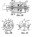
- the driver means 46 is best illustrated in Figure 3, and includes a DC motor comprising a housing 52, a pair of elongate field magnets 53 and 54 each being affixed at radially opposing positions within the housing 52 and having a peaked portion 67 or 68 projecting inwardly from the housing 52, and an armature 55 rotatably mounted within the housing 52.
- the armature 55 has a generally cylindrical first portion 56 and a second portion including a semi-cylindrical side 57 and an angulated side 58.
- the angulated side 58 includes two radially opposing peak shaped projections 69 and 70 symmetrically disposed about the axis of rotation of the armature 55, and a planar surface 59 connecting these projections.
- the field magnets 53 and 54 will tend to rotate the armature 55 to a position where the magnetic flux is the most concentrated. This occurs when the projections 69 and 70 are proximate the projections 67 and 68 of the field magnets 53 and 54. It is to this position that the armature 55 tends to return when there are no competing magnetic forces tending to move it elsewhere.
- the DC motor 50 also includes a cylindrical driving coil 44 affixed in the housing 52 concentric with the cylindrical first portion 56 of the armature 55. As previously described, this coil 44 is electrically connected to the phase comparison means, with any current from the output of the phase comparison means passing through the coil 44 and causing a second magnetic field to develop which magnetizes the semi-cylindrical side 57.
- the rotation of the armature 55 rotates the playback head 22 about an axis perpendicular to the medium 16, a distance and direction determined by the output current of the servo driver 42.
- This rotation changes the angle of the playback head gaps with respect to tracks on the recorded medium 16.
- the present invention contains mechanical means to limit any excess rotation of the DC motor 50. In the preferred embodiment, this is accomplished by a pair of stops 60 rigidly connected to the housing 52, an arm 62 connected to a shaft 61, and adjustment screws 63 passing through the arm 62 and positioned to contact the stops 60 during the rotation of the shaft 61. These screws 63 can be adjusted to vary the maximum rotation of the shaft 61.
- the center of the armature 55 is drilled and a hollow brass shaft 61 is inserted in the resulting bore.
- This shaft 61 allows wires 66 from the playback head to pass through the center of the DC motor 50, which minimizes the extraneous forces that the head wires 62 might otherwise exert against the rotation of the armature 55.
- This shaft 61 also provides a convenient means of bringing the head wires 62 from the head 22 to the amplifiers.
- the cylindrical coil 44 is wound on a plastic bobbin which is cemented to one end of the field magnets 53 and 54. This permits the armature 55 ' to rotate within the coil 44 without disturbing magnetic induction and the soldering of the leads from the coil directly to the fixed terminals without concern for flexibility or commutation.
Landscapes
- Adjustment Of The Magnetic Head Position Track Following On Tapes (AREA)
Applications Claiming Priority (2)
| Application Number | Priority Date | Filing Date | Title |
|---|---|---|---|
| US06/211,265 US4433351A (en) | 1980-11-28 | 1980-11-28 | System for reducing phase error in multitrack magnetic recording |
| US211265 | 2005-08-25 |
Publications (3)
| Publication Number | Publication Date |
|---|---|
| EP0053430A2 true EP0053430A2 (de) | 1982-06-09 |
| EP0053430A3 EP0053430A3 (en) | 1983-01-05 |
| EP0053430B1 EP0053430B1 (de) | 1987-04-22 |
Family
ID=22786187
Family Applications (1)
| Application Number | Title | Priority Date | Filing Date |
|---|---|---|---|
| EP81304678A Expired EP0053430B1 (de) | 1980-11-28 | 1981-10-08 | System zum Reduzieren des Phasenfehlers bei magnetischer Mehrspuraufzeichnung |
Country Status (4)
| Country | Link |
|---|---|
| US (1) | US4433351A (de) |
| EP (1) | EP0053430B1 (de) |
| JP (1) | JPS57117120A (de) |
| DE (1) | DE3176139D1 (de) |
Families Citing this family (5)
| Publication number | Priority date | Publication date | Assignee | Title |
|---|---|---|---|---|
| US4686588A (en) * | 1983-11-01 | 1987-08-11 | Nakamichi Corporation | Azimuth adjustment apparatus for a magnetic head |
| DE3521437A1 (de) * | 1983-11-29 | 1986-12-18 | Sharp K.K., Osaka | Mehrspur-magnetbandgeraet und verfahren zur spureinstellung seiner wiedergabekoepfe |
| US7644192B2 (en) * | 2005-08-25 | 2010-01-05 | Hitachi Global Storage Technologies Netherlands B.V | Analyzing the behavior of a storage system |
| US8194884B1 (en) * | 2006-08-23 | 2012-06-05 | Adobe Systems Incorporated | Aligning time variable multichannel audio |
| CN111158135B (zh) * | 2020-03-04 | 2024-06-07 | 崔恩博 | 一种适用于地平式望远镜的修正装置及方法 |
Family Cites Families (16)
| Publication number | Priority date | Publication date | Assignee | Title |
|---|---|---|---|---|
| GB202287A (en) * | 1922-08-10 | 1924-04-24 | Walter Anderhub | Improvements in steam-turbine driven locomotives |
| US2751439A (en) * | 1955-03-31 | 1956-06-19 | Rca Corp | Magnetic recording apparatus |
| US2938962A (en) * | 1955-07-12 | 1960-05-31 | Konins | Azimuth seeking reproducing head |
| US3204228A (en) * | 1955-11-16 | 1965-08-31 | Sperry Rand Corp | Signal synchronizer |
| US2937239A (en) * | 1956-02-13 | 1960-05-17 | Gen Electric | Skew servo for multiple channel recording system |
| GB925603A (en) * | 1960-12-21 | 1963-05-08 | Vectron Electro Physics Ltd | Compensation of irregularities in motion of a recording medium |
| NL288467A (de) * | 1962-02-05 | |||
| DE1188845B (de) * | 1963-04-11 | 1965-03-11 | Siemens Ag | Verfahren und Schaltungsanordnung zur Unterdrueckung von Stoersignalen in einer Anordnung zur maschinellen Erkennung von Schriftzeichen |
| US3387295A (en) * | 1965-06-24 | 1968-06-04 | Minnesota Mining & Mfg | Skew correction apparatus utilizing a torsionally deformable capstan |
| US3526726A (en) * | 1967-09-27 | 1970-09-01 | Ampex | Piezoelectric transducer assembly for positioning a magnetic record/reproduce head |
| JPS5171918A (en) * | 1974-12-19 | 1976-06-22 | Matsushita Electric Industrial Co Ltd | Puranjaa |
| JPS5180904A (ja) * | 1975-01-13 | 1976-07-15 | Shinshu Seiki Kk | Kaidoki |
| US4101937A (en) * | 1976-11-11 | 1978-07-18 | International Tapetronics Corporation | Automatic azimuth control for magnetic tape recording and reproducing apparatus |
| JPS5389723A (en) * | 1977-01-19 | 1978-08-07 | Toshiba Corp | Azimuth adjuster of recorder-reproducer |
| JPS55132524A (en) * | 1979-04-02 | 1980-10-15 | Matsushita Electric Ind Co Ltd | Control unit of relative angle between magnetic head and magnetic tape |
| US4258398A (en) * | 1979-10-12 | 1981-03-24 | Eastman Kodak Company | Apparatus for preventing flutter and skew in electrical signals |
-
1980
- 1980-11-28 US US06/211,265 patent/US4433351A/en not_active Expired - Lifetime
-
1981
- 1981-10-08 DE DE8181304678T patent/DE3176139D1/de not_active Expired
- 1981-10-08 EP EP81304678A patent/EP0053430B1/de not_active Expired
- 1981-11-27 JP JP56190455A patent/JPS57117120A/ja active Pending
Also Published As
| Publication number | Publication date |
|---|---|
| EP0053430B1 (de) | 1987-04-22 |
| EP0053430A3 (en) | 1983-01-05 |
| US4433351A (en) | 1984-02-21 |
| JPS57117120A (en) | 1982-07-21 |
| DE3176139D1 (en) | 1987-05-27 |
Similar Documents
| Publication | Publication Date | Title |
|---|---|---|
| US5619383A (en) | Method and apparatus for reading and writing audio and digital data on a magnetic tape | |
| US5189572A (en) | Magnetic control of a transducer signal transfer zone to effect tracking of a path along a record medium | |
| US2938962A (en) | Azimuth seeking reproducing head | |
| US4055849A (en) | Magnetic head positioning and playback apparatus utilizing a split head for self-tracking and selective reproduction | |
| KR960016898B1 (ko) | 디지탈 신호의 전송계에 있어서 손실된 저주파수 성분을 재생하여 보상하기 위한 직류 재생회로 | |
| US4433351A (en) | System for reducing phase error in multitrack magnetic recording | |
| EP0037715A1 (de) | Vorrichtung zum Positionieren des Abtastkopfes eines Videomagnetband-Wiedergabegerätes mit schraubenförmiger Abtastung | |
| KR920003616B1 (ko) | 비디오 레코더 | |
| GB2088618A (en) | Method and apparatus for recording/reproducing control signal in a video tape recorder | |
| US2513653A (en) | Magnetic record transducing head | |
| US4525696A (en) | Driver for rotating a magnetic playback head | |
| JP2595752B2 (ja) | 磁気記録再生装置 | |
| US4385327A (en) | Audio system having a time base error correction arrangement | |
| US4472752A (en) | Magnetic head | |
| US4675760A (en) | Information signal recording and/or playback system and method using a prerecorded reference track | |
| JP2542070B2 (ja) | 磁気記録再生装置のトラツキング装置 | |
| JPS5951046B2 (ja) | 磁気記録再生装置のトラツキング装置 | |
| US2912517A (en) | Magnetic tape apparatus | |
| EP0265487A4 (en) | Magnetically controlled scanning magnetic head tracking control system | |
| JP2772176B2 (ja) | 磁気ヘッドのアジマス調整方法 | |
| JP3182770B2 (ja) | タイムコード信号記録回路 | |
| KR0123534B1 (ko) | 트랙가이드가 수행되는 레코더 | |
| JP3161628B2 (ja) | 磁気記録再生装置 | |
| CA1203020A (en) | Audio system having a time base error correction arrangement | |
| JPH0316103Y2 (de) |
Legal Events
| Date | Code | Title | Description |
|---|---|---|---|
| PUAI | Public reference made under article 153(3) epc to a published international application that has entered the european phase |
Free format text: ORIGINAL CODE: 0009012 |
|
| AK | Designated contracting states |
Designated state(s): CH DE FR GB IT NL |
|
| PUAL | Search report despatched |
Free format text: ORIGINAL CODE: 0009013 |
|
| AK | Designated contracting states |
Designated state(s): CH DE FR GB IT LI NL |
|
| 17P | Request for examination filed |
Effective date: 19830629 |
|
| ITF | It: translation for a ep patent filed | ||
| GRAA | (expected) grant |
Free format text: ORIGINAL CODE: 0009210 |
|
| AK | Designated contracting states |
Kind code of ref document: B1 Designated state(s): CH DE FR GB IT LI NL |
|
| REF | Corresponds to: |
Ref document number: 3176139 Country of ref document: DE Date of ref document: 19870527 |
|
| ET | Fr: translation filed | ||
| PLBE | No opposition filed within time limit |
Free format text: ORIGINAL CODE: 0009261 |
|
| STAA | Information on the status of an ep patent application or granted ep patent |
Free format text: STATUS: NO OPPOSITION FILED WITHIN TIME LIMIT |
|
| 26N | No opposition filed | ||
| REG | Reference to a national code |
Ref country code: GB Ref legal event code: 732 |
|
| PGFP | Annual fee paid to national office [announced via postgrant information from national office to epo] |
Ref country code: CH Payment date: 19900827 Year of fee payment: 10 |
|
| PGFP | Annual fee paid to national office [announced via postgrant information from national office to epo] |
Ref country code: GB Payment date: 19900831 Year of fee payment: 10 |
|
| PGFP | Annual fee paid to national office [announced via postgrant information from national office to epo] |
Ref country code: FR Payment date: 19900919 Year of fee payment: 10 |
|
| PGFP | Annual fee paid to national office [announced via postgrant information from national office to epo] |
Ref country code: DE Payment date: 19900921 Year of fee payment: 10 |
|
| ITTA | It: last paid annual fee | ||
| PGFP | Annual fee paid to national office [announced via postgrant information from national office to epo] |
Ref country code: NL Payment date: 19901031 Year of fee payment: 10 |
|
| PG25 | Lapsed in a contracting state [announced via postgrant information from national office to epo] |
Ref country code: GB Effective date: 19911008 |
|
| PG25 | Lapsed in a contracting state [announced via postgrant information from national office to epo] |
Ref country code: LI Effective date: 19911031 Ref country code: CH Effective date: 19911031 |
|
| PG25 | Lapsed in a contracting state [announced via postgrant information from national office to epo] |
Ref country code: NL Effective date: 19920501 |
|
| GBPC | Gb: european patent ceased through non-payment of renewal fee | ||
| NLV4 | Nl: lapsed or anulled due to non-payment of the annual fee | ||
| PG25 | Lapsed in a contracting state [announced via postgrant information from national office to epo] |
Ref country code: FR Effective date: 19920630 |
|
| REG | Reference to a national code |
Ref country code: CH Ref legal event code: PL |
|
| PG25 | Lapsed in a contracting state [announced via postgrant information from national office to epo] |
Ref country code: DE Effective date: 19920701 |
|
| REG | Reference to a national code |
Ref country code: FR Ref legal event code: ST |