EP0053462A1 - Mit Flüssigkeit betriebenes Temperatursteuerungssystem für ein Fahrzeug - Google Patents
Mit Flüssigkeit betriebenes Temperatursteuerungssystem für ein Fahrzeug Download PDFInfo
- Publication number
- EP0053462A1 EP0053462A1 EP19810305492 EP81305492A EP0053462A1 EP 0053462 A1 EP0053462 A1 EP 0053462A1 EP 19810305492 EP19810305492 EP 19810305492 EP 81305492 A EP81305492 A EP 81305492A EP 0053462 A1 EP0053462 A1 EP 0053462A1
- Authority
- EP
- European Patent Office
- Prior art keywords
- inlet
- valve
- fluid
- bleed
- valve element
- Prior art date
- Legal status (The legal status is an assumption and is not a legal conclusion. Google has not performed a legal analysis and makes no representation as to the accuracy of the status listed.)
- Ceased
Links
Images


Classifications
-
- B—PERFORMING OPERATIONS; TRANSPORTING
- B60—VEHICLES IN GENERAL
- B60H—ARRANGEMENTS OF HEATING, COOLING, VENTILATING OR OTHER AIR-TREATING DEVICES SPECIALLY ADAPTED FOR PASSENGER OR GOODS SPACES OF VEHICLES
- B60H1/00—Heating, cooling or ventilating devices
- B60H1/00642—Control systems or circuits; Control members or indication devices for heating, cooling or ventilating devices
- B60H1/0065—Control members, e.g. levers or knobs
-
- B—PERFORMING OPERATIONS; TRANSPORTING
- B60—VEHICLES IN GENERAL
- B60H—ARRANGEMENTS OF HEATING, COOLING, VENTILATING OR OTHER AIR-TREATING DEVICES SPECIALLY ADAPTED FOR PASSENGER OR GOODS SPACES OF VEHICLES
- B60H1/00—Heating, cooling or ventilating devices
- B60H1/00642—Control systems or circuits; Control members or indication devices for heating, cooling or ventilating devices
- B60H1/00814—Control systems or circuits characterised by their output, for controlling particular components of the heating, cooling or ventilating installation
- B60H1/00821—Control systems or circuits characterised by their output, for controlling particular components of the heating, cooling or ventilating installation the components being ventilating, air admitting or air distributing devices
- B60H1/00835—Damper doors, e.g. position control
- B60H1/00842—Damper doors, e.g. position control the system comprising a plurality of damper doors; Air distribution between several outlets
-
- Y—GENERAL TAGGING OF NEW TECHNOLOGICAL DEVELOPMENTS; GENERAL TAGGING OF CROSS-SECTIONAL TECHNOLOGIES SPANNING OVER SEVERAL SECTIONS OF THE IPC; TECHNICAL SUBJECTS COVERED BY FORMER USPC CROSS-REFERENCE ART COLLECTIONS [XRACs] AND DIGESTS
- Y10—TECHNICAL SUBJECTS COVERED BY FORMER USPC
- Y10T—TECHNICAL SUBJECTS COVERED BY FORMER US CLASSIFICATION
- Y10T137/00—Fluid handling
- Y10T137/8593—Systems
- Y10T137/86493—Multi-way valve unit
- Y10T137/86879—Reciprocating valve unit
Definitions
- This invention relates to temperature or environmental control systems for the passenger or operator compartments of vehicles and more particularly to a manual control assembly for such systems.
- Vehicles such as trucks and passenger cars typically include an environmental control or temperature control system for directing and conditioning outside air or recirculating air within the passanger or operator compartment.
- the systems include duct work having a fresh air inlet, a heat outlet directing air towards the floor of the compartment, a defrost outlet for directing air towards the windscreen, and vent and air conditioning outlets.
- a heater for example a coil or core, is supported within the duct work. If so equipped, an air conditioner evaporator coil will also be.positioned within the duct work.
- a plurality of doors are supported in the duct work for selectively directing.air in the various modes of operation.
- Typical systems include a fresh air door, a heat door and a defrost door. Further, a blower is provided to pull air through the evaporator coil, towards the heater coil and through the outlets.
- the air conditioning unit will typically have two modes of operation. In a Max A/C Mode of operation, air within the compartment is recirculated through the evaporator coil. In a Normal A/C Mode, outside or fresh air plus a predetermined amount of recirculated air is passed through the evaporator coil and into the passenger compartment. When operating in a Vent Mode, air from the outside is passed directly into the compartment through the vent outlets. In the Heat Mode, outside air plus a predetermined amount of recirculated air is passed over the heater coil and towards the floor of the vehicle compartment.
- the heated air will be passed to the floor of the vehicle and the remaining.percentage will be directed through the defrost outlets to the windscreen.
- the Defrost Mode of operation the majority of the air will be passed to the defrost outlets and approximately 10-30% of the air will pass to the heat outlets.
- the air conditioner compressor is operated and air is passed over the evaporator coils and then to the defrost outlets. A portion of the air is directed through the heat outlets and towards the floor of the vehicle compartment.
- a blend air door may also be included in the duct work to proportion the amount of air passed through or around the heater coil thereby to control the temperature of the outlet air.
- Such systems would also include a shut-off water vavle which controls flow of engine coolant through the heater coil.
- the shut-off water valve may be cable or vacuum actuated.
- Some systems do not include the blend air door but include a proportional water valve actuated through a lever and cable arrangement.
- the blower motor is typically controlled through a.multi-position or speed blower motor switch.
- the doors or dampers within the duct work are positioned by vacuum operated diaphragm actuators. Vacuum from the intake manifold of the engine is selectively directed or diverted to the diaphragm actuators by a control assembly. Electrical controls are also provided for selectively actuating the air conditioning compressor and for controlling the blower motor speed.
- a fluid actuator control valve for use in a vehicle environment and comfort control system, the system being of the type including duct work interconnecting a fresh air inlet with a vent outlet, a heater outlet and a defrost outlet and further including a movable fresh air door, a movable heat door, and a movable defrost door mounted in said duct work, the doors being shiftable between first and second positions by fluid actuators, said control valve directing actuating fluid selectively to the actuators for said doors and characterised by:
- an actuator lever for moving the valve element is supported on the housing and defines a cam surface which selectively actuates a compressor electrical switch for operation of the system in an Air Conditioning and/or Defog Mode.
- the control assembly supports a multi-position blower switch for controlling the speed of the blower.
- a temperature control lever may be supported on the valve element housing and connected to a blend air door or to a water valve through a cable. Seal,means are provided in the inlet cavities or chambers and in the outlet passages and which engage the valve element. The seal means ensure that fluid under pressure will pass through the ports and/or passages of the element without leaking into the chamber.
- the valve housing is easily manufactured in two pieces, namely, a front piece and a back piece.
- the front piece defines the inlet passage which is connected to the inlet cavities.
- the back piece defines the outlet passages which are readily connectable to the door actuators.
- the slide valve element is a planar member which defines an array of throughbores and bleed ports.
- the throughbores permit fluid to pass from an inlet cavity which is aligned with an outlet passage.
- the bleed ports are connected to bleed passages which permit air to bleed back from the actuators and out of the valve housing.
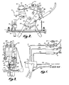
- the preferred temperature control system 10 which is shown in plan view in simplified form in Figure 1 includes a manual control assembly 12, a fresh air door 14, a heat door 16 and a defrost door 18.
- the doors are pivotally supported within duct work which is schematically shown and generally designated 20.
- the doors 14, 16 and 18 are selectively positionable in the various modes of operation of the temperature control system 10.
- These doors are movable between first and second positions by actuators 2.2, 24 and 26, respectively.
- Each.actuator is preferably of the piston cylinder type including a piston 28 and a rod 30 pivotally connected to a bracket 32 on each door.
- a spring 34 is disposed within each cylinder to bias the piston 28 to the left, when viewed in Figure 1, so that the doors are normally in the first position shown.
- a conduit 40 connects the control assembly 12 to a fluid supply.
- system 10 is of the type used in a heavy-duty vehicle, such as a semi tractor, and the conduit 40 is connected to a source of pressurized air.
- the actuators are connected to the assembly 12 by tubes 42, 44 and 46, respectively.
- the assembly 12 includes a valve housing 48 which includes a valve front member 50 and a valve back member 52.
- the valve front member 50 includes a bracket 54 to which a control lever 56 is pivotally supported.
- the valve front member 50 also includes a lower bracket 58 to which a temperature control lever 60 is pivotally supported.
- the lever 56 is a mode control lever.
- the assembly 12 further includes a support plate 62-to which the valve housing 48 is secured at a bracket 64.
- the support plate 62 also carries a control panel or face plate 66.
- the Mode control lever 56 and the temperature control lever 60 extend through slots .68, 70, respectively, in the control panel 66 ( Figure 4).
- the control panel 66 includes indicia which designate the various modes of operation of the system 10. As shown in Figure 4, these modes include a Max A/C (Air Conditioning) Mode, a Normal A/C Mode, a Vent Mode, a Heat Mode, a Defrost Mode and a Defog Mode.
- the panel 66 also indicates movement of the temperature control lever 60 from a cool position to a warm position.
- a compressor switch 80 is supported on a bracket 82 carried by the valve back 52 member.
- the compressor switch 80 is electrically connected to a compressor in an air conditioning system (not shown).
- the switch 80 includes a shiftable contact 84 having a follower surface 86 positioned to engage a cam surface 88 defined by the mode control lever 56.
- the lever 56 and can surface 88 selectively actuate the switch 80 in the Max A/C, Normal A/C and Defog Modes of operation.
- Also supported on the support plate 62 immediately behind the control panel 66 is a multi-position blower speed control switch 90 which includes an acutating lever 92 which extends through a slot 94 ( Figure 4) in control panel 66.
- the panel 66 includes suitable indicia 96 indicating three positions and hence three speeds of operation of a blower motor (not shown) positioned in the duct work of the system.
- the system 10 is a temperature or environmental control system for a vehicle which would include a suitable blower connected to the switch 90 and which draws outside air into the vehicle or recirculates air within the vehicle.
- the system would further include a heater core or coil, an evaporator, a vent outlet, a heat outlet and a defrost outlet. Since these portions of the system are conventional, they have not been illustrated. Reference may be had to the aforementioned United States patents for a showing of such conventional portions of a temperature control system.
- the system lO. may employ a blend door to proportion fresh air and conditioned air or a system which employs a proportional water valve to control the temperature of the air in the Heat Mode.
- the temperature control lever 60 is connected to the water valve or blend door through a suitable cable assembly 100 ( Figures 1 and 2). As the lever 60 is moved from the "cool” to the "warm” position along the slot 70, more air would be proportioned to pass through or around the heater coil of the system or increased water from the vehicle's engine coolant system would be passed to the heater coil. Since these arrangements are well-known in the art, they are not.described in detail here.
- valve front 50 and the valve back 52 of the valve assembly 48 define a slot 110 opening through the upper and lower sides of the valve assembly.
- a slide valve element 112 Slidably positioned within the slot-like cavity or chamber 110 is a slide valve element 112 which includes a vertical post 114 disposed within a slot 116 defined by the mode control lever 56.
- pivotal movement of the mode control lever 56 will shift the slide valve element 112 within the slot 110.
- control panel 66 supports a detent plate 120 having a plurality of apertures 122 formed therein, these apertures corresponding to the mode control positions of the valve assembly.
- a spring loaded detent 124 is carried by the lever 56 and includes a plunger 126 biased into the apertures 122.
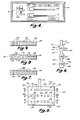
- the slide valve element l12 is illustrated in detail in Figures 5 to 9.
- the element 112 includes a generally planar, elongated or block-like member 130 which includes a leading edge 132, a trailing edge 134 and upper and lower transverse edges 136, 138.
- the member 130 defines a front face or surface 140 and a rear face or surface 142 and further defines an array of throughbores or control passages 144 and an.array of bleed ports 146. Each bleed port opens through rear face 142 and into one of a plurality of bleed passages 148.
- the member 130 is divided into three horizontal row areas 150, 152 and 154.
- the member 130 as illustrated in Figure 5, could also be considered to be divided into six vertical row areas equally spaced horizontally from leading edge 132 to trailing edge 134.- This will be discussed below in connection with the description of Figures 23 to 34.
- the upper horizontal row area 150 includes a throughbore 144 and five bleed ports 146.
- the bleed ports 146 all communicate with a single bleed passage 148 which opens through the trailing edge 134 of the member 130.
- the intermediate horizontal row area 152 includes from leading edge 132 to trailing edge 1.34, three bleed ports 146 opening into a bleed passage 148 which in turn opens through the leading edge 132, a throughbore 144 and two trailing bleed ports 146 opening into a passage 148 which in turn opens through the trailing edge 134.
- the lower horizontal row area 154 includes three throughbores 144 and three bleed ports 146.
- the bleed ports 146 open into a lower bleed passage 148 which in turn opens through the trailing edge 134.
- each of the horizontal row areas or portions 150, 152-and 154 are separated by narrow web portions 160.
- the first vertical row area defined by member 130 includes an upper throughbore, an intermediate bleed port and a lower throughbore.
- the second vertical row area includes an upper bleed port, an intermediate bleed port and a lower throughbore.
- the third vertical area includes an upper bleed port, an intermediate bleed port and a lower throughbore.
- the fourth vertical row area includes an upper bleed port, an intermediate throughbore and a lower bleed port.
- the fifth and sixth vertical areas which correspond to the fifth and sixth positions of the valve element, include upper intermediate and lower bleed ports. This is explained further below.
- the valve back member 52 is illustrated in detail in Figures 10 to 14.
- the valve back member 52 is a generally planar, elongated member including an upper longitudinal edge 160, a lower longitudinal edge 162, a leading end 164 and a trailing end 166.
- Extending rearwardly from the valve back 52 is a support bracket 168.
- the support bracket 168 is used to secure the valve back to the support plate 62.
- the compressor switch support bracket 82 is formed integral with and extends rearwardly from the valve back element 52.
- the bracket 82 includes elongated slots 170 which permit adjustment and the positioning of the compressor switch 80 to ensure operation of the movable contact 84, as explained below.
- the member 52 further defines a back, planar surface 174. Disposed centrally of the surface 174 is a vertical row of outlet passages 176, 178 and 180. The centrelines or central axes 182, 184 and 186 of the passages all lie in the same vertical plane. As seen in Figures lO and 11, the valve back 52 also defines a plurality of bosses 188, 190 and 192 which extend rearwardly of the valve back element. The bosses define through passages or outlet passages 189, 191 and 193. Passages 189, 191 and 193 are each separated from passages 176, 178 and 180 by restrictions 194 each defined by a ring 196.
- the leading end 164 and trailing end 166 of the valve back member extend outwardly perpendicular to the surface 174 and also define securement tab apertures 198.
- the boss 192 is connected through the tube 42 to the fresh air door actuator 22, the boss 190 is connected to the heat door actuator 24 through the tube 44 and the boss 192 is connected to the defrost door actuator 26 through the tube 46.
- the tubes 42, 44 and 46 are connected to their respective bosses through suitable elbow joints and fittings 200.
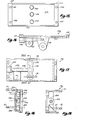
- valve front member 50 is illustrated in detail in Figures 15 to 19. As shown therein, the valve front 50 is an elongated, generally rectangular member including an upper side 210, a front end 212, a rear end 214 and a lower side 216. The ends 212, 214 extend outwardly from a front surface 218 and define mounting apertures 220.
- the front member 50 includes an integral portion 224 defining an inlet passage 226 which is connectable to the source of fluid through the tube 40 by a suitable connector at an inlet portion 228.
- the inlet passage 226 extends longitudinally of the valve front member 50 and communicates with a vertically extending passage 230 which is defined by an integral portion 232.
- the integral portion 232 also defines a plurality of inlet cavities or chambers 234, 236 and 238.
- the inlet cavities include central axes 240, 242 and 244, respectively ( Figure 18). Fluid entering the inlet passage 226 will be communicated to each of the cavities 234, 236 and 238.
- the cavities open through the surface 218 of the valve front member 50.
- valve assembly 48 is assembled by placing the valve element 112 between the faces 174, 218 of the valve back and front members,respectively, and then securing the valve back and front members together at mounting apertures 198, 220 by suitable fasteners.
- the valve front and back members therefore, define the elongated slot-like cavity or valve chamber 110 of the valve housing.
- the inlet cavities and outlet passages are arranged in opposed, paired, coaxial relationship.
- the horizontal rows 150, 152 and 154 of the valve element 112 lie in the same plane as the central axes of the inlet and outlet passages. Therefore, throughbores 144 and bleed ports 146 in each row are coaxial and alignable with the inlet cavities and outlet passages in the various positions of the valve element.
- each seal element 260 is disposed in each inlet cavity.
- a seal element 260 is also disposed in each outlet passage 176, 178 and 180.
- Each seal element 260 is biased into engagement with a face of .the slide valve element 110 by a coil spring schematically illustrated in Figure 20 and designated 262.
- each seal element 260 includes a central, cylindrical portion 264, a flange 266 defining a front face 268 and a flange 270 defining a rear end face 272.
- the element 260 further defines a through passage or bore 274.
- Each element 260 is fabricated from a resilient, non-metallic or plastic material.
- face 268 When in position within either an inlet cavity or outlet passage, face 268 is in sliding and sealing engagement with a front or rear face of the valve element 112.
- An O-ring seal 275 extends around the portion 264.
- the springs 262 bias the seal elements into sealing engagement and contact with the valve element 112. Air under pressure entering the inlet cavities through the passage 226 and the throughbores 144 cannot pass by the faces 268 of the seals and hence into the cavity defined by the front and back members 50, 52.
- the face 268 seals against the valve element, and the O-ring seal 275 seals with the inner peripheral surface of each inlet cavity and outlet passage ( Figure 20).
- the seal elements 260 and O-rings 275 ensure that the air passes into the bleed ports 146 defined by the valve element.
- the seal elements 260 and the springs 262 compensate for wear of the slide valve element l12 and reduce the criticality of manufacturing tolerances. This increases the ease of manufacture and reliability of the valve assembly in use.
- valve element 112, valve back member 52 and valve front member 50 may be easily and relatively inexpensively manufactured employing conventional casting or moulding processes. Machining or finishing steps are minimized, as is wasted material.
- the valve back member 52 is readily cast with the support brackets and mounting brackets formed integral therewith.
- the bosses 188, 190 and 192 may then be drilled and counterbored to define the outlet passage and the annular ring 196.
- the springs 262 in the outlet passages abut against such annular rings.
- the passages could be moulded in the valve back.
- valve front 50 is readily cast and the inlet passage 226 drilled and counterbored or moulded in the portion 224.
- the passage 230 is easily drilled or moulded in the portion 232 from the top edge 210.
- the upper edge 210 is sealed by a suitable plug 280.
- the inlet cavities 234, 236 and 238 may be machined through the surface 218 or formed during the casting process.
- the valve element 112 is readily cast and throughbores 144, bleed ports 146 and bleed passages 148 easily drilled or machined or moulded into and through the slide valve element.
- the valve assembly is adapted to divert or control pressurized air, and manufacturing tolerances and leakage problems associated with vacuum actuators and control assemblies are substantially alleviated.
- the valve element l12 is readily modified by addition or deletion of rows of apertures and bleed ports to adapt the assembly to the desired system. For example, vertical rows may be eliminated if the system is basic and only includes Heat, Vent and Defrost Modes of operation. Wear of the valve element during use as it slides back and forth within the slot.110 is readily compensated for by the seal means including the plugs or pad-like elements 260 and the springs 262. Solenoids and other electromechanical actuators which have been previously used in temperature control systems are dispensed with. The system is completely manually controlled through the mode control lever 56 and the temperature control lever 60.
- FIG. 23 to 34 The operation of the assembly 12 in accordance with the present invention is illustrated in Figures 23 to 34.
- positioning of the valve element 112 in any one of the selected positions within the slot 110 selectively permits passage of air from the inlet cavities to selected ones of the outlet passages. The air then passes through the tubes 42, 44, 46 to the actuators 22, 24, 26 to position the doors within the duct work for the various modes of operation of the control system.
- the bleed ports and passages selectively positioned in front of the outlet passages of the valve back permit pressurized air to bleed back from the actuators and to be expelled through the open top and/or bottom of the slot 110.
- Figures 23 and 24 illustrate the positioning of the valve element when the control lever 56 is in the Max A/C Mode of operation.
- the fresh air door is shifted from its first position, illustrated in Figure.l, to a second position to close off the fresh air inlet of the system.
- the defrost door actuator is also shifted from its first to its second position and the heat door actuator is in the position illustrated in Figure 1.
- the compressor switch engages an "on" position of the cam 88.
- valve element 112 when in the Max A/C position, the valve element 112 is positioned towards the right, and the throughbores 144 of the first vertical row are aligned with the inlet cavities 234., 238 and outlet passages 176, 180.
- pressurized air will pass through the valve element into the tubes 42, 44 thereby shifting the fresh air door 14 and defrost door 18 by the actuators 22, 26, respectively.
- a bleed port 146 of the intermediate horizontal row area and the first vertical row is aligned with the outlet passage 178.
- air from the actuator 24 may pass back through the line 44 and out of the bleed passage 148.
- the contact 84 of the compressor switch 80 will ride on the raised portion of the cam 88 thereby closing the switch 80 and actuating the compressor of the air conditioning system.
- the Normal A/C Mode is illustrated in Figures 25 and 26.
- fresh air is pulled into the duct work by the blower and allowed to pass through.the evaporator coil.
- the second vertical row of the valve element 112 is positioned between the inlet cavities and outlet passages. Air is bled from the fresh air door actuator 22 and heat door actuator 24. Air passes through a throughbore 144 to the defrost door actuator 26.
- the fresh air and heat door are in the first positions shown in Figure 1, and the defrost door is shifted to its second position within the duct work.
- the third vertical row of the slide valve 112 When in the Vent Mode position, the third vertical row of the slide valve 112 is brought into position between the inlet cavities and the outlet passages. When in this position, the bleed ports 246 of the upper and intermediate horizontal row areas of the valve element are aligned with the outlet passages 176, 178. The throughbore 144 of the lower horizontal row area of the slide element is brought into alignment with the inlet cavity 238 and outlet passage 180. As a result, air is bled off from the fresh air door actuator 22 and the heat door actuator 24. Air, however, passes to the defrost door actuator 26. The compressor switch 80 will enter the reduced or "off" portion of cam 88 and the contact 84 will shift away from its fixed contact. As a result, the compressor of the air conditioning system is turned off. Fresh outside air is passed into the vehicle through the vent ducts of the duct work.
- the Heat Mode of operation is schematically illustrated in Figures 29 and 30.
- the fourth vertical row of slide valve 112 When in the heat position, the fourth vertical row of slide valve 112 is placed in the same vertical plane as the inlet cavities and outlet passages.
- a bleed port 146 of the upper horizontal row area of the valve element 112 is aligned with the outlet passage 176
- a bleed port 146 of the lower horizontal row area is aligned with the outlet passage 180
- a throughbore 144 of the intermediate row area is aligned with the inlet cavity 36 and outlet passage 178.
- air is bled off from the fresh air.door actuator 22.and the defrost door actuator 46. Air is passed to the heat door actuator 24. Movement of the temperature control lever 60 controls the temperature of the air in the Heat Mode.
- the Defrost and Defog Modes of operation are illustrated in Figures 31, 32 and 33, 34, respectively.
- the positioning of the doors 14, 16 and 18 are identical in each of these modes of operation.
- the fifth vertical row of the three horizontal row areas of slide-valve element 112 is aligned with the inlet cavities and outlet passages.
- this vertical row includes three bleed ports. 146.
- air is bled off from the fresh air door actuator 22, the heat door actuator 24 and the defrost door actuator 26.
- the majority of the air drawn into the duct work by the blower is then directed towards the windscreen at the defrost outlets of the duct system.
- the compressor switch remains in the "off" portion of the cam 88. No air passes from inlet passage 226 to the outlet passages of the valve back.
- valve element 112 could, therefore, be formed only with the third, fourth and fifth vertical row arrangements of throughbores and bleed ports on the horizontal row areas of the valve element 112. Only three detent positions need be provided for the control lever 156. The remaining elements of the valve assembly would remain the same. As a result, the subject control assembly is readily adaptable to temperature control systems.
- An identical valve element as illustrated and described could be used in a vent, heat and defrost system with the range of travel or movement of the valve limited by suitable stops supported on the mounting plate 62 so that only three detent positions are provided.
- the control assembly in accordance with the present invention is easily and relatively inexpensively manufactured.
- the configuration of the valve front and back members which define the valve hous.ing, the configuration of the slide valve element and the use of the sealing means reduces the criticality of manufacturing tolerances. Reliability in use is achieved.
- control assembly is readily adapted to perform other functions.
- an additional vertical row of throughbores and bleed ports could be included to position the doors so that air is delivered to air conditioning outlets and the heater outlet in approximately equal quantities to provide a bi-level mode or feature.
- Such a mode is desired in a blend air system during which the air conditioning compressor would be actuated to furnish cooling to the air conditioning outlets.
- the control assembly readily employs pressurized air available on trucks and other vehicles to control the positioning of the doors in available temperature control systems. Adaption to the various systems is accomplished through substitution of the valve element to provide the desired direction of actuating air. Compensation for valve element wear and/or seal wear is readily achieved with the resilient springs which bias the seal members into engagement with the front and rear faces of the valve element.
Landscapes
- Physics & Mathematics (AREA)
- Thermal Sciences (AREA)
- Engineering & Computer Science (AREA)
- Mechanical Engineering (AREA)
- Multiple-Way Valves (AREA)
- Air-Conditioning For Vehicles (AREA)
Applications Claiming Priority (2)
| Application Number | Priority Date | Filing Date | Title |
|---|---|---|---|
| US06/208,661 US4427056A (en) | 1980-11-20 | 1980-11-20 | Air actuated vehicle temperature control system |
| US208661 | 1980-11-20 |
Publications (1)
| Publication Number | Publication Date |
|---|---|
| EP0053462A1 true EP0053462A1 (de) | 1982-06-09 |
Family
ID=22775485
Family Applications (1)
| Application Number | Title | Priority Date | Filing Date |
|---|---|---|---|
| EP19810305492 Ceased EP0053462A1 (de) | 1980-11-20 | 1981-11-20 | Mit Flüssigkeit betriebenes Temperatursteuerungssystem für ein Fahrzeug |
Country Status (7)
| Country | Link |
|---|---|
| US (1) | US4427056A (de) |
| EP (1) | EP0053462A1 (de) |
| JP (1) | JPS57114718A (de) |
| AU (1) | AU545740B2 (de) |
| CA (1) | CA1164212A (de) |
| ES (2) | ES8303201A1 (de) |
| MX (1) | MX154726A (de) |
Cited By (3)
| Publication number | Priority date | Publication date | Assignee | Title |
|---|---|---|---|---|
| FR2575238A1 (fr) * | 1984-12-20 | 1986-06-27 | Valeo | Dispositif de commande d'organes mobiles, tels que des volets d'une installation de chauffage et de ventilation ou de climatisation pour vehicule automobile |
| FR2591542A1 (fr) * | 1985-12-13 | 1987-06-19 | Valeo | Dispositif de commande en deplacement d'un organe mobile, tel qu'un volet dans une installation de chauffage et de ventilation ou de climatisation pour vehicule automobile. |
| US6069554A (en) * | 1994-07-07 | 2000-05-30 | Adobe Systems Incorporated | Memory having both stack and queue operation |
Families Citing this family (14)
| Publication number | Priority date | Publication date | Assignee | Title |
|---|---|---|---|---|
| JPS6150821A (ja) * | 1984-08-20 | 1986-03-13 | Nissan Motor Co Ltd | 車両用空調装置 |
| JPH0113614Y2 (de) * | 1985-03-15 | 1989-04-21 | ||
| US4727766A (en) * | 1986-06-04 | 1988-03-01 | Indak Manufacturing Corp. | Heat regulating mechanism for automotive heating and air conditioning systems |
| JPH0717149B2 (ja) * | 1987-11-25 | 1995-03-01 | 日産自動車株式会社 | 自動車用空調装置 |
| US4880031A (en) * | 1988-04-27 | 1989-11-14 | Sprague Aristo-Aire, Inc. | Heater and air conditioning control system |
| GB8920488D0 (en) * | 1989-09-11 | 1989-10-25 | Rover Group | A heat exchanger for a motor vehicle and a temperature control system |
| US5281049A (en) * | 1992-04-14 | 1994-01-25 | Sprague Aristo-Aire, Inc. | Air direction control means for vehicle climate control means |
| US6009934A (en) * | 1996-10-31 | 2000-01-04 | Calsonic Corporation | Electronic climate control system for automotive vehicles |
| US8662968B2 (en) * | 2010-04-30 | 2014-03-04 | GM Global Technology Operations LLC | Air-based hybrid battery thermal conditioning system |
| US8978803B2 (en) | 2012-06-11 | 2015-03-17 | GM Global Technology Operations LLC | Divided dual inlet housing for an air-based hybrid battery thermal conditioning system |
| US9833643B2 (en) * | 2014-04-03 | 2017-12-05 | Mark Squibb | Apparatus for providing controlled flow of inhalation-air |
| RU176960U1 (ru) * | 2017-08-07 | 2018-02-02 | Ильдар Шакирович Сафин | Кондиционер транспортного средства |
| US11717634B2 (en) | 2018-10-02 | 2023-08-08 | MaxxO2, LLC | Therapeutic oxygen breathing apparatus and exercise system |
| CN114872516B (zh) * | 2022-04-27 | 2025-02-28 | 宁波均胜群英汽车系统股份有限公司 | 一种汽车空调的出风系统 |
Citations (5)
| Publication number | Priority date | Publication date | Assignee | Title |
|---|---|---|---|---|
| US2914629A (en) * | 1958-04-23 | 1959-11-24 | Chrysler Corp | Control device |
| US3731729A (en) * | 1972-02-07 | 1973-05-08 | Gen Motors Corp | Selector/programmer assembly for automatic temperature control |
| DE2403316A1 (de) * | 1974-01-24 | 1975-08-07 | Sueddeutsche Kuehler Behr | Steuervorrichtung fuer klimaanlagen |
| US3942555A (en) * | 1974-03-25 | 1976-03-09 | Indak Manufacturing Corporation | Electrical switch and fluid control device |
| FR2376981A1 (fr) * | 1977-01-11 | 1978-08-04 | Renault | Distributeur pneumatique a boutons poussoirs notamment pour les commandes de climatisation d'un vehicule automobile |
Family Cites Families (16)
| Publication number | Priority date | Publication date | Assignee | Title |
|---|---|---|---|---|
| US2790605A (en) | 1952-02-07 | 1957-04-30 | Vapor Heating Corp | Water by-pass control for bus heating system |
| US3060967A (en) | 1959-09-04 | 1962-10-30 | Electro Hydraulics Ltd | Selector valve mechanism |
| US3370612A (en) | 1964-10-19 | 1968-02-27 | Robert W. Holl | Four-way ball valve |
| US3428115A (en) | 1967-01-26 | 1969-02-18 | Ranco Inc | Automotive temperature control |
| US3441213A (en) | 1968-01-23 | 1969-04-29 | United Aircraft Corp | Pneumatic air temperature control system |
| US3465962A (en) | 1968-03-29 | 1969-09-09 | Garrett Corp | Electro-pneumatically controlled air conditioning system |
| US3828821A (en) | 1968-10-08 | 1974-08-13 | J Dotter | Pressure regulator faucet slide valve |
| US3575209A (en) | 1969-02-24 | 1971-04-20 | Gen Electric | Fluidic position limit control |
| US3637962A (en) | 1971-03-29 | 1972-01-25 | Theodore E Fiddler | A rotary control device for actuating a switch and directing a fluid pressure force |
| US3744523A (en) | 1971-07-21 | 1973-07-10 | J Hill | Fluid pilot valve |
| JPS5226374B2 (de) | 1973-05-14 | 1977-07-13 | ||
| US3983930A (en) | 1973-09-24 | 1976-10-05 | Eaton Corporation | Temperature control system and multifunctional servomotor therefor |
| SE390332B (sv) | 1974-10-02 | 1976-12-13 | Stal Laval Turbin Ab | Manoverventil for att forbinda ett antal forbrukningsstellen med ett gemensamt tillopp |
| DE2808702C2 (de) | 1977-03-01 | 1984-05-24 | Mitsubishi Jidosha Kogyo K.K., Tokio/Tokyo | Anzeige- und Steuerungseinrichtung für eine Lüftungs-/ Heizungs-/Kühlanlage eines Kraftfahrzeuges |
| US4147205A (en) | 1977-09-12 | 1979-04-03 | The Bendix Corporation | Vacuum actuated automatic temperature control system with actuator pressure signal feedback |
| GB1593481A (en) | 1978-02-23 | 1981-07-15 | Mitsubishi Motors Corp | Vehicle heating and ventilating assembly |
-
1980
- 1980-11-20 US US06/208,661 patent/US4427056A/en not_active Expired - Lifetime
-
1981
- 1981-11-02 AU AU77036/81A patent/AU545740B2/en not_active Ceased
- 1981-11-03 CA CA000389303A patent/CA1164212A/en not_active Expired
- 1981-11-12 MX MX190090A patent/MX154726A/es unknown
- 1981-11-19 ES ES507292A patent/ES8303201A1/es not_active Expired
- 1981-11-20 JP JP18558981A patent/JPS57114718A/ja active Pending
- 1981-11-20 EP EP19810305492 patent/EP0053462A1/de not_active Ceased
-
1982
- 1982-10-11 ES ES516416A patent/ES8400707A1/es not_active Expired
Patent Citations (5)
| Publication number | Priority date | Publication date | Assignee | Title |
|---|---|---|---|---|
| US2914629A (en) * | 1958-04-23 | 1959-11-24 | Chrysler Corp | Control device |
| US3731729A (en) * | 1972-02-07 | 1973-05-08 | Gen Motors Corp | Selector/programmer assembly for automatic temperature control |
| DE2403316A1 (de) * | 1974-01-24 | 1975-08-07 | Sueddeutsche Kuehler Behr | Steuervorrichtung fuer klimaanlagen |
| US3942555A (en) * | 1974-03-25 | 1976-03-09 | Indak Manufacturing Corporation | Electrical switch and fluid control device |
| FR2376981A1 (fr) * | 1977-01-11 | 1978-08-04 | Renault | Distributeur pneumatique a boutons poussoirs notamment pour les commandes de climatisation d'un vehicule automobile |
Cited By (7)
| Publication number | Priority date | Publication date | Assignee | Title |
|---|---|---|---|---|
| FR2575238A1 (fr) * | 1984-12-20 | 1986-06-27 | Valeo | Dispositif de commande d'organes mobiles, tels que des volets d'une installation de chauffage et de ventilation ou de climatisation pour vehicule automobile |
| EP0188142A1 (de) * | 1984-12-20 | 1986-07-23 | Valeo | Steuerungseinrichtung für bewegliche Teile, insbesondere Heizungs- und Lüftungsklappe oder Klappe für PKW-Klimaanlage |
| US4757744A (en) * | 1984-12-20 | 1988-07-19 | Valeo | Apparatus for controlling flaps in an installation for heating and ventilating or for air-conditioning a motor vehicle |
| FR2591542A1 (fr) * | 1985-12-13 | 1987-06-19 | Valeo | Dispositif de commande en deplacement d'un organe mobile, tel qu'un volet dans une installation de chauffage et de ventilation ou de climatisation pour vehicule automobile. |
| EP0229545A1 (de) * | 1985-12-13 | 1987-07-22 | Valeo | Betätigungseinrichtung für Heizungs- und Lüftungs- oder Klimaanlagen in Kraftfahrzeugen |
| US4735127A (en) * | 1985-12-13 | 1988-04-05 | Valeo - Societe Anonyme Francaise | Device for controlling the displacement of a moving member such as a flap in an installation for heating and ventilating or for air conditioning a motor vehicle |
| US6069554A (en) * | 1994-07-07 | 2000-05-30 | Adobe Systems Incorporated | Memory having both stack and queue operation |
Also Published As
| Publication number | Publication date |
|---|---|
| ES516416A0 (es) | 1983-11-01 |
| US4427056A (en) | 1984-01-24 |
| ES507292A0 (es) | 1983-02-01 |
| ES8303201A1 (es) | 1983-02-01 |
| ES8400707A1 (es) | 1983-11-01 |
| MX154726A (es) | 1987-12-07 |
| AU7703681A (en) | 1982-05-27 |
| AU545740B2 (en) | 1985-08-01 |
| JPS57114718A (en) | 1982-07-16 |
| CA1164212A (en) | 1984-03-27 |
Similar Documents
| Publication | Publication Date | Title |
|---|---|---|
| EP0053462A1 (de) | Mit Flüssigkeit betriebenes Temperatursteuerungssystem für ein Fahrzeug | |
| US3983930A (en) | Temperature control system and multifunctional servomotor therefor | |
| US6962195B2 (en) | Vehicle heating and air conditioning modules | |
| US5016704A (en) | Air conditioner system for automotive vehicle | |
| US4390124A (en) | Heating and ventilation system for vehicles | |
| US5106018A (en) | Heating and ventilating apparatus for the cabin of an automotive vehicle | |
| US5505251A (en) | Cooling and air conditioning apparatus for an electric vehicle | |
| US4582252A (en) | Heater unit for an automotive vehicle air conditioner | |
| JPS6246706A (ja) | 自動車用暖房兼空気調和装置 | |
| US5101883A (en) | Method of assembly of single and multi-zone vehicle heating and a/c systems | |
| EP0699547A2 (de) | Heisswasserheizung für Fahrzeuge | |
| US4898325A (en) | Automobile air conditioner with separate flow adjustment for central and side vents | |
| US4834170A (en) | Air conditioner for automobiles | |
| US4125150A (en) | Ventilating and heating apparatus or air-conditioning apparatus, especially for motor vehicles | |
| US4709751A (en) | Vehicular air conditioner with defogging feature | |
| US3774676A (en) | Automotive vehicle automatic temperature control system | |
| GB2237411A (en) | Air-conditioning for vehicles | |
| US3807631A (en) | Heating,ventilating and defrosting system for vehicles | |
| US4346729A (en) | Temperature control system and pushbutton controlled pneumatic actuator | |
| US2966032A (en) | Heating and ventilating system for motor vehicles | |
| JPS5951452B2 (ja) | 車両用空気調和装置における制御システム | |
| US4757744A (en) | Apparatus for controlling flaps in an installation for heating and ventilating or for air-conditioning a motor vehicle | |
| US5092521A (en) | Heater system for the passenger compartment of a motor vehicle | |
| US4212322A (en) | Linear vacuum programmer | |
| US5467960A (en) | Two-way HVAC fluid control valve |
Legal Events
| Date | Code | Title | Description |
|---|---|---|---|
| PUAI | Public reference made under article 153(3) epc to a published international application that has entered the european phase |
Free format text: ORIGINAL CODE: 0009012 |
|
| AK | Designated contracting states |
Designated state(s): AT BE CH DE FR GB IT NL SE |
|
| 17P | Request for examination filed |
Effective date: 19821124 |
|
| STAA | Information on the status of an ep patent application or granted ep patent |
Free format text: STATUS: THE APPLICATION HAS BEEN REFUSED |
|
| 18R | Application refused |
Effective date: 19860509 |
|
| RIN1 | Information on inventor provided before grant (corrected) |
Inventor name: JOHNSON, THOMAS J. Inventor name: THOMAS, GARTH L. |