EP0053480A1 - Echange de tuyaux - Google Patents
Echange de tuyaux Download PDFInfo
- Publication number
- EP0053480A1 EP0053480A1 EP81305588A EP81305588A EP0053480A1 EP 0053480 A1 EP0053480 A1 EP 0053480A1 EP 81305588 A EP81305588 A EP 81305588A EP 81305588 A EP81305588 A EP 81305588A EP 0053480 A1 EP0053480 A1 EP 0053480A1
- Authority
- EP
- European Patent Office
- Prior art keywords
- main
- mole
- liner
- existing
- new
- Prior art date
- Legal status (The legal status is an assumption and is not a legal conclusion. Google has not performed a legal analysis and makes no representation as to the accuracy of the status listed.)
- Granted
Links
- 238000000034 method Methods 0.000 claims abstract description 15
- 230000001681 protective effect Effects 0.000 claims abstract description 6
- 239000012530 fluid Substances 0.000 claims description 6
- 238000003780 insertion Methods 0.000 claims description 2
- 230000037431 insertion Effects 0.000 claims description 2
- 229910001018 Cast iron Inorganic materials 0.000 abstract description 12
- 229920003023 plastic Polymers 0.000 abstract description 11
- 239000004033 plastic Substances 0.000 abstract description 11
- 239000000463 material Substances 0.000 abstract description 5
- 239000004698 Polyethylene Substances 0.000 abstract description 2
- -1 polyethylene Polymers 0.000 abstract description 2
- 229920000573 polyethylene Polymers 0.000 abstract description 2
- 229910000831 Steel Inorganic materials 0.000 description 13
- 239000010959 steel Substances 0.000 description 13
- 230000008878 coupling Effects 0.000 description 3
- 238000010168 coupling process Methods 0.000 description 3
- 238000005859 coupling reaction Methods 0.000 description 3
- 230000037361 pathway Effects 0.000 description 3
- 238000009412 basement excavation Methods 0.000 description 2
- 238000002360 preparation method Methods 0.000 description 1
- 238000003466 welding Methods 0.000 description 1
Images


Classifications
-
- E—FIXED CONSTRUCTIONS
- E21—EARTH OR ROCK DRILLING; MINING
- E21B—EARTH OR ROCK DRILLING; OBTAINING OIL, GAS, WATER, SOLUBLE OR MELTABLE MATERIALS OR A SLURRY OF MINERALS FROM WELLS
- E21B7/00—Special methods or apparatus for drilling
- E21B7/28—Enlarging drilled holes, e.g. by counterboring
- E21B7/30—Enlarging drilled holes, e.g. by counterboring without earth removal
-
- F—MECHANICAL ENGINEERING; LIGHTING; HEATING; WEAPONS; BLASTING
- F16—ENGINEERING ELEMENTS AND UNITS; GENERAL MEASURES FOR PRODUCING AND MAINTAINING EFFECTIVE FUNCTIONING OF MACHINES OR INSTALLATIONS; THERMAL INSULATION IN GENERAL
- F16L—PIPES; JOINTS OR FITTINGS FOR PIPES; SUPPORTS FOR PIPES, CABLES OR PROTECTIVE TUBING; MEANS FOR THERMAL INSULATION IN GENERAL
- F16L55/00—Devices or appurtenances for use in, or in connection with, pipes or pipe systems
- F16L55/16—Devices for covering leaks in pipes or hoses, e.g. hose-menders
- F16L55/162—Devices for covering leaks in pipes or hoses, e.g. hose-menders from inside the pipe
- F16L55/165—Devices for covering leaks in pipes or hoses, e.g. hose-menders from inside the pipe a pipe or flexible liner being inserted in the damaged section
- F16L55/1658—Devices for covering leaks in pipes or hoses, e.g. hose-menders from inside the pipe a pipe or flexible liner being inserted in the damaged section the old pipe being ruptured prior to insertion of a new pipe
-
- Y—GENERAL TAGGING OF NEW TECHNOLOGICAL DEVELOPMENTS; GENERAL TAGGING OF CROSS-SECTIONAL TECHNOLOGIES SPANNING OVER SEVERAL SECTIONS OF THE IPC; TECHNICAL SUBJECTS COVERED BY FORMER USPC CROSS-REFERENCE ART COLLECTIONS [XRACs] AND DIGESTS
- Y10—TECHNICAL SUBJECTS COVERED BY FORMER USPC
- Y10T—TECHNICAL SUBJECTS COVERED BY FORMER US CLASSIFICATION
- Y10T225/00—Severing by tearing or breaking
- Y10T225/30—Breaking or tearing apparatus
- Y10T225/371—Movable breaking tool
-
- Y—GENERAL TAGGING OF NEW TECHNOLOGICAL DEVELOPMENTS; GENERAL TAGGING OF CROSS-SECTIONAL TECHNOLOGIES SPANNING OVER SEVERAL SECTIONS OF THE IPC; TECHNICAL SUBJECTS COVERED BY FORMER USPC CROSS-REFERENCE ART COLLECTIONS [XRACs] AND DIGESTS
- Y10—TECHNICAL SUBJECTS COVERED BY FORMER USPC
- Y10T—TECHNICAL SUBJECTS COVERED BY FORMER US CLASSIFICATION
- Y10T29/00—Metal working
- Y10T29/53—Means to assemble or disassemble
- Y10T29/53652—Tube and coextensive core
-
- Y—GENERAL TAGGING OF NEW TECHNOLOGICAL DEVELOPMENTS; GENERAL TAGGING OF CROSS-SECTIONAL TECHNOLOGIES SPANNING OVER SEVERAL SECTIONS OF THE IPC; TECHNICAL SUBJECTS COVERED BY FORMER USPC CROSS-REFERENCE ART COLLECTIONS [XRACs] AND DIGESTS
- Y10—TECHNICAL SUBJECTS COVERED BY FORMER USPC
- Y10T—TECHNICAL SUBJECTS COVERED BY FORMER US CLASSIFICATION
- Y10T83/00—Cutting
- Y10T83/384—By tool inside hollow work
Definitions
- the present invention relates to the replacement or the preparation for replacement of an existing main, particularly an existing cast iron gas main, with a new main and is particularly concerned with a method and a device for enabling this replacement to be carried out.
- Mains have to be replaced for a number of reasons, for instance, the existing main may be in poor condition or the existing main may not be of sufficient capacity t.o aecomodate a modified load.
- a method for replacing or preparing for replacement an existing main with a new,main comprising fracturing the existing main and maintaining sufficient clearance through the fractured main for movement therethrough of a new main or a liner for the fractured main, the liner to serve as a protective sleeve for the new main when the new main is subsequently moved into the liner.
- the new main is presleeved with the liner before the new main is moved through the fractured main.
- the existing main is continuously fractured ahead of the moving new main or liner.
- the internal diameter of the new main is equal to or greater than the internal diameter of the existing main.
- the clearance provides a bore whose diameter is greater than the external diameter of the existing main.
- the clearance provides a bore whose diameter is greater than the external diameter of the new main ⁇ or the liner.
- a device for replacing or preparing for replacement an existing main with a new main, the device comprising a mole for insertion into and movement along the existing main, the mole having a front portion provided with a cutting face for engaging the internal wall of the existing main and arranged to cause the wall to fracture and a rear porion provided with means for clamping to the mole the new main or a liner for the existing main so that the mole tows the new main or the liner through the fractured main as the mole moves therethrough.
- the front portion comprises a head portion provided with a cutting face and a body portion of at least. the same diameter as the largest diameter of the head portion.
- the forward end of the mole is adapted for connection to a cable of a winch.
- the cutting face comprises edges on the head portion of the mole which edges are adapted to engage and fracture the wall of the existing main as the mole moves therethrough.
- the cutting face preferably tapers radially inwardly in the direction of the front end of the mole.
- the cutting edges may comprise blades, at least one of which is movable radially outwardly from the mole to engage and fracture the wall of the existing main.
- the cutting edges lie in an axial plane of the mole.
- the or each movable blade is pivotally mounted on the mole.
- movable means located within the mole may be provided to engage the movable blade or blades to cause the movable blade or blades to pivot.
- each blade is pivotally movable and the mole has an internal bore defined in part by portions of the blades and the movable means is located within the bore.
- the movable means comprises an hydraulically acutated ram.
- only one blade is pivotally movable and the movable means comprises an hydraulically actuated piston.
- the mole may be provided with a duct for supplying hydraulic fluid to the piston, the duct extending into the mole from its forward end.
- means are preferbly located within the mole for driving the mole through the existing main.
- the driving means comprises a pneumatically actuated hammer for engaging the mole to drive it percussively through the existing main.
- the hammer is located within a bore in the mole.
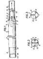
- Figure 1 shows a steel mole 1 having a front portion consisting of a head portion 2 and a cylindrical body portion 3 and a rear portion having clamping means 4 for clamping a new main.
- the head portion 2 has a cutting face 5 comprising three or more cutting edges 6 formed by grinding high tensile steel cutters 7 (four cutters are shown in Figures 1 and 2).
- the cutters 7 are housed in Keyways (not shown) in the head portion 2, which is in the form of a cylinder tapering towards the front end of the mole, the cutters 7 being attached to the head portion 2 by means of bolts (not shown) so that the cutters 7 are removable from the head portion 2.
- the cutting face 5 tapers radially inwardly in the direction of the forward end of the mole 1, that is, the radii of the cutting edges 6 decrease towards the forward end of the mole 1 so as to enable the cutting face 5 to exert a continuously increasing cutting action on the existing main 8 as the mole 1 moves therethrough.
- the cutting face 5 terminates at rearward points 9 on the head portion 2, which points 9 are concentrically aligned with the periphery of the body portion 3 and the keyways are arranged on the head portion 2 so that the cutters 7 and their cutting edges 6 in position on the mole 1 lie in an axial plane of the mole 1.
- the front end of the head portion 2 is provided with a housing 10 cast into the head portion 2 and provided with an eye 11 to enable the mole 1 to be connected to a steel winch cable (not shown).
- the rear portion of the mole 1 is provided with a clamping means 4 in the form of a sleeve 12 secured to the body portion 3 and being of slightly smaller external diameter than that of the body portion 3.
- the sleeve 12 in use, receives the end of the new main 13 which is of a flexible material such as plastics.
- the end of the new main 13 is first surrounded by a protective plastics sleeve 14 and the main 13 and sleeve 14 are pushed into the clamping sleeve 12. This is arranged to have an internal diameter approximately equal to the external diameter of the new main 13 so that this fits securely within and is tightly gripped and clamped by the clamping sleeve 12.
- the cutters 7 are arranged to be spaced equianguarly around the axis of the cutting face 5 as s.hown in Figures 2 and 3 and the taper of the cutting face 5 prevents the mole 1 from twisting and turning on its horizontal axis thereby preventing undue strain on the new main and associated pneumatic feedlines (not shown).
- the ground at either end of the existing cast iron main 8 is excavated to expose those ends.
- the steel cable of a motorised winch is fed through the main 8 from one end and is secured to the shackle housing 10 via the eye 11.
- the new plastic main 13 and its sheath 14 are then clamped to thèiclamping sleeve 12.
- the new plastics main 13 can be of the same or slightly larger internal diameter than the existing cast iron main 8.
- the head portion 2 of the mole 1 is then inserted into the existing cast iron main 8 until the cutting edges 6 engage the end of the main 8 as shown in - Figure 1.
- the cable is then wound onto the winch so as to pull the mole 1 through the existing main 8.
- the rear portion 12 is acted upon by a pneumatic hammer (not shown) to drive the mole 1 into the main 8.
- the combined tension and pneumatic pressure cause the mole 1 to move along the main 8 so that the cutting edges 7 engage the internal wal of the main 8 and cause the wall to fracture due to their intense localised pressure on the wall as the mole 1 moves therethrough.
- the cylindrical body 3 widens out the internal diameter of the fractured main 8 since, in use, the body 3 is selected to have a diameter greater than that of the orginal internal diameter of the main 8. The body 3 also prevents debris from the fractured main and earth from falling into the pathway creasted for the new main.
- the outer diameter of the body portion 3 of the mole 1 is arranged to be about 1/8" greater than the outer diameter of the existing main and the outer diameter of the clamping sleeve 12 is about 1/8" less in diameter than that of the cylindrical body portion 3 of the mole 1.
- Figure 4 shows a steel mole 21 having a front portion consisting of a head portion 22 and a body portion 23 and a rear portion having a clamping means 24 for clamping a new main.
- the head portion 22 has a cutting face 25 comprising three or more pivotally mounted cutting blades 26 (four are present on the mole shown in Figures 4 and 5).
- the blades 26 are disposed in elongated axially directed slots (not shown) in the wall of the head portion 23 and are pivotally mounted at their forward ends 27 to the wall of the head portion 23.
- each blade 26 is arranged to be spaced equiangularly around the axis of the cutting face.
- Each blade 26 has a cutting edge 28 formed by two sloping sides 29, two parallel sides 30 adjoining the sloping sides 29 and a concave side 31 distal from the cutting edge 28 between the parallel sides 30.
- the concave side 31 slopes away from the cutting edge 28'in a direction forwardly of the mole 1.
- the body- portion 23 has a cylindrical rear portion 32, a frustoconical portion 33 tapering forwardly of the mole and a cylindrical front portion 34 adjoining the slot forming walls (not shown) of the head portion 23.
- the body portion 23 is provided with a circular centrally located through-going bore 35 (see Figure 5) which merges with a passageway 36 formed by the concave sides 31 of the blades 26 and the internal concave shaped walls (not shown) of the head portion slot forming walls.
- the passageway-36 merges with a circular centrally located through-going bore 37 located near the forward end of the head portion 23 beyond the pivotted ends 27 of the blades 26.
- the bore 27 is provided with a conical termination 38.
- the bore 35 and passageway 36 house an hydraulically operated cylindrical ram 39 which is capable of movement within the bore 35 and passageway 36.
- the front of the ram 39 is engaged at all times with the concave sides 31 of the blades 26.
- the cutting edges 28 are axially aligned with the front portion 34 of the body portion 23.
- the concave sides 31 of the blades 26 extend further radially into the passageway 36 than do the internal concave shaped walls of the head portion slot forming walls (not shown) so as to permit the blades 26 to pivot outwardly from the closed position in Figure 4 to the open position in Figure 5 as the ram 39 is moved forwardly along the passageway 36 and encounters the radially inward slope of the concave sides 31.
- the front end of the head portion 22 is provided with a housing 40 and an eye 41 similar to that shown in the mole of Figure 1 and for similar purposes.
- the rear portion of mole 21 is provided with a clamping means 24 in the form of a clamping sleeve 42 similar to that shown in the mole in Figure 1.
- the clamping sleeve 42 is secured to the body portion 23 and is of slightly smaller diameter than the rear portion 32 of the body portion 23.
- the new plastics main 43 and its protective sheath 44 are secured and clamped to the clamping sleeve 42 in exactly the same manner as previously described for the mole shown in Figure 1.
- the ground at either end of the existing cast iron main 45 is excavated to expose those ends.
- the steel cable of a motorised winch is fed through the main 45 from one end and is secured to the housing 40 via the eye 41.
- the new plastics main 43 and its sheath 4 are then clamped to the clamping sleeve 42.
- the new plastics main 43 can be of the same or slightly larger internal diameter than the existing cast iron main 45.
- the head portion 22 of the mole 21 is then inserted into the existing main 45 until a portion at least of th cutting blades 26 lie adjacent the internal wall of the existing main 45 as shown in Figure 4.
- the ram 39 is actuated hydraulically to move forwardly within the passageway 36 to cause the blades 26 to pivot about their ends 27 to engage and fracture the cast iron main 45 by the intense localised pressure of their cutting edges 28 upon the internal wall of the main 45 as shown in Figure 5.
- the ram 39 is withdrawn to the position shown in Figure 4 so that the blades 26 return to the closed position of Figure 4.
- the winch cable (not shown) is then wound onto the winch so as to pull the mole 21 through the existing main 45 by an amount not exceeding the length of the blades 26.
- a next portion of the existing main 45 is then fractured by the method just described and the mole 21 is then pulled through the main 45 by a further amount not exceeding the length of blades 26.
- the body portion 23 also prevents debris from the fractured main 45 and earth from falling into the pathway created for the new main 43.
- the mole 21 proceeds along the fractured main 45, it tows the new main 43 with it the internal diameter of the new main 43 being the same or slightly larger than that of the existing main 45.
- the new main 43 and its sheath 44 are removed from the clamping sleeve 42.
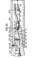
- the steel mole 51 comprises a front portion consisting of a head 52 tapering generally conically towards its front end and a cylindrical rear portion 53 incorporating clamping means 54 for clamping a cylindrical liner for the new main.
- the head portion 52 has a cutting face 55 comprising three blades 56, 57 and 58 disposed in elongated axially directed slots in the wall of the head 52.
- Two lower blades 56 and 57 (shown in Figure 9) are welded or bolted rigidly in the slots so that they are fixed.
- the other upper blade 58 which is wider and thicker than the lower blades, is pivotally mounted at its forward end 59 to the wall of the head portion 52.
- the upper blade 58 pivots on a pin 60 extending through portions (not shown) of the head 52 of the mole 51, the portions forming a recess (not shown) to accommodate movement of the forward end 59 of the blade 58.
- each blade 56 to 58 is spaced equiangularly around the axis of the cutting face which tapers forwardly to the front end of the mole 51.
- Each blade 56 to 58 has a cutting edge 60 formed by two sloping sides 61 and a base 62 distal from the cutting edge 60 and formed between parallel sides 63.
- the head 52 of the mole 51 houses an hydraulically actuated piston 64 slidable within a cylindrical bore 65 within the head 2.
- the bore 65 has a smaller diameter lower bore portion 66 communicating with a wider diameter upper bore portion 67.
- the wall of the bore portion 67 is screw threaded for receiving an externally threaded stop ring 68.
- the stop ring 68 serves to limit the extent of upward movement of the piston 64 when it engages with a lowermost stop collar 69 secured to the periphery of the piston 64.
- the head 52 is provided with a hydraulic fluid channel 70 which at one end communicates with the bore 65 below the piston 64 and terminates in a threaded bore 71 of wider diameter at the front end of the head 52.
- the threaded bore 71 serves to receive the threaded connector of a hydraulic hose coupling 72.
- the front end of head 52 is recessed laterally on two sides to receive and engage the cross-pieces 73 of two adjacent T-shaped cable connecting plates 74 (only one plate 74 shown in the drawings).
- the plates 74 are connected to each other and to the front end of the head 52 by a pair of connecting pins 75 and 76 which extend through the cross-pieces 73 of the plates 74 via the front end of the head portion 52.
- the uprights 77 of the connecting plates 74 extend forwardly of the mole 51 and are connected together by a pin 78 which also forms a connecting point for the cable 79 of a winch (not shown).
- the rear 53 of the mole 51 comprises a generally hollow cylinder adjoining the conically tapering mole head 52.
- the mole 51 forms a housing for a pneumatically actuated hammer device 80.
- the hammer 80 has head portion 81 projecting into an internal bore 82 formed in the head 52 of the mole 51, the rear 83 of the hammer 80 being axially disposed with clearance in the cylindrical rear portion 53 of the mole 51.
- the head portion 81 of the hammer 80 comprises a forwardly co-nically tapering portion 84 terminating in a cylindrical end 85.
- the diameter of the end 85 is less than the diameter of the adjoining end of the conically tapering portion 84 so that there is an annular shoulder 85 formed between the portion 84 and the hammer end 85.
- the portion 84 and the end 85 of the hammer head 81 are, in use, able to cooperatively engage in corresponding portions of the internal bore-82, these portions also forming an annular shoulder for co-operation with the annular shoulder 86 in the hammer head 81.
- a rear part of the hammer head portion 84 is disposed axially with clearance in a wider forwardly conically tapering portion 90 of the internal bore 82, the portion 84 terminating within the rear 53 of the mole 51.
- the rear 83 of the hammer 80 comprises a cylindrical portion 91 terminating in a rearwardly tapering conical po.rtion 92 which is provided with a coupling (not shown) for an air hose 93.
- compressed air supplied to the hammer 80 through the hose 93 causes the hammer 80 to reciprocate in the conventional manner to drive the mole 51 through the existing main 94 by the percussive action of the hammer head 81 upon the corresponding co-operating portions of the internal bore 82 of the mole 51.
- the means 54 for clamping the liner 95 to the mole 51 comprises a steel ring 96 for engaging the rear .end of the liner 95, a looped cable 97 connected to the ring 96, a tensioning cable 98 connected to the cable 97, a clamping cup 99 for engaging the far end of the liner 95 and a locking device 100 for locking the cable 98 immovably against the cup 99.
- the steel ring 96 is secured as by welding within and to the internal wall of the rear portion 53 of the mole 51.
- the ring 96 is formed with holes (not shown) to enable the ends of the looped steel cable 97 to be secured thereto.
- the clamping cup 99 which is also of steel is adapted to receive and locate the far end of the liner 95 and is apertured (not shown) for the passage therethrough of the air hose 93 and of the tensioning cable 98.
- the tensioning cable 98 which is also of steel, is coupled by a conventional hitch 101 at one end to the looped cable 97 and is connected via its other end to a winch (not shown).
- the locking device 100 comprises a clamping block which has an axial bore therethrough for permitting the block to be slidable on the tensioning cable 98 and screws 102 for clamping the block to the cable 98.
- the ground at either end of the existing cast iron main 94 is excavated to expose the ends of the main 94.
- the steel cable 79 of a motorised winch is then fed through the main 94 from one end and is secured to mole 51 located at the other end of the main 103.
- the cable 79 is connected to the clamping plates 74 by way of the clamping pin 78.
- the hydraulic hose 103 is fed through the same end of the main 94 as the cable 79 and is coupled to the fluid bore 71 in the mole head 52 by way of the hose coupling 72.
- the liner 95 is clamped to the mole 51. Initially; the looped cable 97 is secured to the ring 96 and the cable 97 is then secured to the tensioning cable 98 which has the clamp block 100. The liner 95 is then pushed up the cylindrical portion 53 of the mole 51 until one end of the liner 95 engages with the ring 96. The clamping cup 99 is then slid along the tensioning cable 98 and the air hose 93 until the other end of the liner 95 is located within and engages with the cup 99.
- the tensioning cable 98 is then tensioned by coiling it onto the winch and after the tension in the cable 98 is deemed to be sufficient, the clamping block 100 is slid along the cable 98 until it engages with the base of the cup 99 as shown in Figure 8.
- the screws 102 are then screwed into engagement with the tensioning cable 98 to clamp it securely against the clamping cup 99.
- the liner 95 is then clamped compressively between the clamping cup 99 and the ring 96.
- the tensioning cable 98 is now released from the winch.
- the internal diameter of the .liner 95 is greater than the internal diameter of the existing cast iron main 94.
- the head portion 52 of the mole 51 is then inserted into the cast iron main 103 until the cutting edges 60 of the blades 56, 57 and 58 engage the end of the main 103 as shown in the drawings.
- the pneumatic hammer 80 is actuated by supplying compressed air to its rear end by way of the air hose 93 so that the hammer 80 percussively drives the mole 51 through the main 94.
- the mole 51 is drawn through the main 94 by the cable 79 which serves to guide the mole 51 axially through the main 94.
- the cutting edges 60 engage the internal wall of the main 94 and cause it to fracture. Since the cylindrical portion 53 of the mole 51 has a greater external diameter than the internal diameter of the main 94, the internal diameter of the fractured main 94 is widened out.
- the body 53 of the mole 51 also serves to provide clearance for'the passage of the liner 95 therethrough and prevents debri from the fractured main and earth from falling into the pathway created for the liner 95.
- the movable blade 58 is pivotted outwardly to fracture the obstruction and provide a clearance for the liner.
- hydraulic fluid is pumped to the piston 64 via the hose 103, duct 70 and the cylinder bore 65.
- the fluid pressure is relaxed immediately after the obstruction has been fractured so that the piston 64 relaxes and the blade 58 returns to its closed position.
- the hose 103 is of course moved simultaneously forward with the mole 51.
- the liner 95 is pushed through and out of the main 103 after complete fracture thereof to expose the clamping cup 99 and block 100.
- the new main may be of any convenient plastics material such as polyethylene or pvc while the liner is of a much tougher wear resistant plastics material.
Landscapes
- Engineering & Computer Science (AREA)
- Mining & Mineral Resources (AREA)
- Geology (AREA)
- General Engineering & Computer Science (AREA)
- Life Sciences & Earth Sciences (AREA)
- Geochemistry & Mineralogy (AREA)
- Fluid Mechanics (AREA)
- Environmental & Geological Engineering (AREA)
- Physics & Mathematics (AREA)
- Mechanical Engineering (AREA)
- General Life Sciences & Earth Sciences (AREA)
- Earth Drilling (AREA)
- Excavating Of Shafts Or Tunnels (AREA)
- Springs (AREA)
- Catching Or Destruction (AREA)
- Cultivation Of Plants (AREA)
- Protection Of Plants (AREA)
- Drilling And Exploitation, And Mining Machines And Methods (AREA)
Priority Applications (1)
| Application Number | Priority Date | Filing Date | Title |
|---|---|---|---|
| DE8383105111T DE3176812D1 (de) | 1980-12-02 | 1981-11-26 | Mains insertion |
Applications Claiming Priority (2)
| Application Number | Priority Date | Filing Date | Title |
|---|---|---|---|
| GB8038655 | 1980-12-02 | ||
| GB8038655 | 1980-12-02 |
Related Child Applications (2)
| Application Number | Title | Priority Date | Filing Date |
|---|---|---|---|
| EP83105111.5 Division-Into | 1983-05-24 | ||
| EP84305529.4 Division-Into | 1984-08-21 |
Publications (3)
| Publication Number | Publication Date |
|---|---|
| EP0053480A1 true EP0053480A1 (fr) | 1982-06-09 |
| EP0053480B1 EP0053480B1 (fr) | 1987-08-05 |
| EP0053480B2 EP0053480B2 (fr) | 1992-07-29 |
Family
ID=10517720
Family Applications (2)
| Application Number | Title | Priority Date | Filing Date |
|---|---|---|---|
| EP81305588A Expired - Lifetime EP0053480B2 (fr) | 1980-12-02 | 1981-11-26 | Echange de tuyaux |
| EP83105111A Expired - Lifetime EP0094694B2 (fr) | 1980-12-02 | 1981-11-26 | Insertion de canalisations principales |
Family Applications After (1)
| Application Number | Title | Priority Date | Filing Date |
|---|---|---|---|
| EP83105111A Expired - Lifetime EP0094694B2 (fr) | 1980-12-02 | 1981-11-26 | Insertion de canalisations principales |
Country Status (7)
| Country | Link |
|---|---|
| US (3) | US4505302A (fr) |
| EP (2) | EP0053480B2 (fr) |
| JP (1) | JPS6027873B2 (fr) |
| CA (3) | CA1191356A (fr) |
| DE (2) | DE3176344D1 (fr) |
| GB (5) | GB2092701B (fr) |
| IE (3) | IE52282B1 (fr) |
Cited By (16)
| Publication number | Priority date | Publication date | Assignee | Title |
|---|---|---|---|---|
| US4602495A (en) * | 1982-06-18 | 1986-07-29 | Yarnell Ian Roland | Device and method for removing irregularities in or enlarging an underground duct |
| EP0190933A3 (fr) * | 1985-02-06 | 1987-05-13 | Pirelli Construction Company Limited | Remplacement de tuyaux |
| EP0182551A3 (en) * | 1984-11-20 | 1987-09-30 | Alh Systems Limited | Mole mole |
| EP0209686A3 (en) * | 1985-07-23 | 1987-10-28 | Ruhrgas Aktiengesellschaft | Process and device for pretreating an old underground pipeline for replacement by a new one |
| EP0324463A1 (fr) * | 1988-01-14 | 1989-07-19 | Hans Brochier GmbH & Co | Dispositif pour l'élargisssement de tuyaux |
| DE3902081C1 (fr) * | 1989-01-25 | 1989-07-27 | Hans Brochier Gmbh & Co, 8500 Nuernberg, De | |
| DE3940354A1 (de) * | 1989-06-14 | 1990-12-20 | Paul Speeck Gmbh & Co Kg | Verfahren zum grabenlosen entfernen eines erdverlegten rohres aus dem umgebenden erdreich und vorrichtung zur durchfuehrung des verfahrens |
| EP0411278A1 (fr) * | 1989-08-02 | 1991-02-06 | Tracto-Technik Paul Schmidt, Maschinenfabrik Kg | Procédé et dispositif pour la destruction d'une conduite enterrée |
| DE4328618A1 (de) * | 1993-08-26 | 1995-03-02 | Teerbau Gmbh Strassenbau | Verfahren zur Erneuerung unterirdisch verlegter Rohre und Kanäle |
| DE19527138C1 (de) * | 1995-07-25 | 1996-07-04 | Terra Ag Tiefbautechnik | Vorrichtung zum Ersetzen einer alten Versorgungsleitung durch eine neue Leitung |
| DE19512602C1 (de) * | 1995-03-31 | 1996-09-26 | Tracto Technik | Vorrichtung zum Rammen von Rohren oder zum Aufweiten von Pilotbohrungen oder Ersetzen erdverlegter Rohrleitungen |
| EP0869308A3 (fr) * | 1997-04-02 | 1999-06-23 | TERRA AG fuer Tiefbautechnik | Dispositif de tirage d'un tuyau dans un puit |
| AU741343B2 (en) * | 1998-04-22 | 2001-11-29 | Tracto-Technik Paul Schmidt Spezialmaschinen | Widening apparatus |
| RU2225917C2 (ru) * | 2001-07-04 | 2004-03-20 | Общество с ограниченной ответственностью "Комстек-92" | Ударный механизм для пробивания скважин и устройство для бестраншейной замены подземных трубопроводов на его основе |
| CN111720623A (zh) * | 2020-07-07 | 2020-09-29 | 海南前途工程设计有限公司 | 一种非开挖引入管施工方法 |
| WO2021239691A1 (fr) * | 2020-05-27 | 2021-12-02 | De Handwarkers Gmbh | Outil de broyage oscillant et procédé de retrait d'un tuyau posé dans le sol |
Families Citing this family (129)
| Publication number | Priority date | Publication date | Assignee | Title |
|---|---|---|---|---|
| EP0053480B2 (fr) * | 1980-12-02 | 1992-07-29 | British Gas plc | Echange de tuyaux |
| US4657436A (en) * | 1982-06-18 | 1987-04-14 | I.P.D. Systems Limited | Device and method for removing irregularities in or enlarging an underground duct |
| GB8333567D0 (en) * | 1983-12-16 | 1984-01-25 | Yarnell Ian Roland | Removing irregularities in/enlarging underground duct |
| US4789268B2 (en) * | 1982-06-18 | 1995-12-26 | Miller Pipeline Corp | Device and method for removing irregularities in or enlarging an underground duct |
| GB2123111A (en) * | 1982-06-21 | 1984-01-25 | British Gas Corp | Repairing mains |
| US4507019A (en) * | 1983-02-22 | 1985-03-26 | Expand-A-Line, Incorporated | Method and apparatus for replacing buried pipe |
| GB2137719B (en) * | 1983-03-31 | 1987-01-28 | Daly Limited P N | Pipe replacement |
| GB2149472A (en) * | 1983-11-10 | 1985-06-12 | Merstan Impact Moling Limited | Mole |
| GB8332738D0 (en) * | 1983-12-08 | 1984-01-18 | Merstan Impact Moling Ltd | Pipe laying and replacement |
| GB8401452D0 (en) * | 1984-01-19 | 1984-02-22 | British Gas Corp | Replacing mains |
| GB2167156B (en) * | 1984-11-15 | 1988-06-08 | Expand A Line Inc | Replacing buried pipe |
| US4693404A (en) * | 1985-01-10 | 1987-09-15 | British Gas Corporation | Mains bursting tool |
| FR2578631B1 (fr) * | 1985-03-06 | 1987-05-07 | Litzelmann Andre | Dispositif pour la pose d'un tuyau pour le tubage d'une cheminee |
| US5007767A (en) * | 1985-03-25 | 1991-04-16 | British Gas Corporation | Method for joining polyolefin pipes by fusion |
| DE3533995A1 (de) * | 1985-09-24 | 1987-04-16 | Tracto Technik | Rammbohrgeraet mit schlagmesserkolben |
| US4705116A (en) * | 1985-11-12 | 1987-11-10 | Alh Systems, Ltd. | Mole with rotary vibrator |
| SE450969B (sv) * | 1985-11-25 | 1987-08-17 | Entreprenad Ab E & G Jonsson | Sett for renovering av markforlagda rorledningar |
| JPS62125197A (ja) * | 1985-11-25 | 1987-06-06 | 三井建設株式会社 | 既設管路の交換設置工法 |
| GB8615280D0 (en) * | 1986-06-23 | 1986-07-30 | Rice N | Sewer renovation |
| JPS646590A (en) * | 1987-06-26 | 1989-01-11 | Kurimoto Ltd | Method of replacing existing main pipe with novel main pipe |
| US5002432A (en) * | 1987-07-22 | 1991-03-26 | Dynovation Design & Engineering Inc. | Device and method to cut and coil piles, casings and conductors |
| DE3726532A1 (de) * | 1987-08-10 | 1989-02-23 | Platzer Schwedenbau Gmbh | Verfahren und vorrichtung zur unterirdischen verlegung von heizungsrohren |
| JPH01150087A (ja) * | 1987-12-07 | 1989-06-13 | Kurimoto Ltd | 既設の本管を新しい本管と取り替える方法 |
| GB2214260A (en) * | 1988-01-12 | 1989-08-31 | British Gas Plc | Mole |
| DE3813767C1 (fr) * | 1988-04-23 | 1989-06-29 | Hans Brochier Gmbh & Co, 8500 Nuernberg, De | |
| DE3815232C1 (en) * | 1988-05-05 | 1989-01-05 | Hans Brochier Gmbh & Co, 8500 Nuernberg, De | Pipe-widening apparatus, in particular for disposal lines in refuse landfills |
| US4886396A (en) * | 1988-05-12 | 1989-12-12 | Kabushiki Kaisha Iseki Kaihatsu Koki | Existing pipeline renewing method and apparatus therefor |
| JPH028577A (ja) * | 1988-06-22 | 1990-01-12 | Kubota Ltd | 既設管の非開削による布設替え方法 |
| CA1324619C (fr) * | 1988-07-26 | 1993-11-23 | Kabushiki Kaisha Iseki Kaihatsu Koki | Machine blindee servant a percer des tunnels et equipee d'un element d'etancheite adapte au mouvement d'excentricite |
| DE3829628A1 (de) * | 1988-09-01 | 1990-03-15 | Schmidt Paul | Rammbohrgeraet zum grabenlosen verlegen von versorgungsleitungen |
| US4925344A (en) * | 1989-01-03 | 1990-05-15 | Peres Steve U | Method and apparatus for replacing buried pipe |
| DE3910354C1 (fr) * | 1989-03-30 | 1990-06-28 | Diga - Die Gasheizung Gmbh, 4300 Essen, De | |
| GB2231118B (en) * | 1989-05-06 | 1992-12-16 | D J Ryan & Sons Limited | Pipeline replacement |
| GB2233060A (en) * | 1989-06-09 | 1991-01-02 | British Gas Plc | Pipe burster. |
| FR2663397B1 (fr) * | 1990-06-19 | 1992-11-06 | Gaz De France | Procede et dispositif de remplacement d'une canalisation enterree par projection localisee d'un fluide sous pression. |
| EP0444974A1 (fr) * | 1990-02-01 | 1991-09-04 | Gaz De France | Procédé et dispositif de remplacement d'une canalisation enterrée |
| DE4014775C1 (fr) * | 1990-05-09 | 1991-08-01 | Tracto-Technik Paul Schmidt Maschinenfabrik Kg, 5940 Lennestadt, De | |
| US4983071A (en) * | 1990-05-15 | 1991-01-08 | Consolidated Edison Company Of New York, Inc. | Pipe bursting and replacement apparatus and method |
| US5098225A (en) * | 1990-12-31 | 1992-03-24 | Brooklyn Union Gas | Cutting/expanding tool |
| US5171106A (en) * | 1990-12-31 | 1992-12-15 | Brooklyn Union Gas | Cutting/expanding tool |
| US5067854A (en) * | 1991-02-04 | 1991-11-26 | Aardvark Corporation | Apparatus and technique for installing an elongated rod in an earth formation |
| US5112158A (en) * | 1991-03-25 | 1992-05-12 | Mcconnell W Harry | Underground pipe replacement method and apparatus |
| CA2055421C (fr) * | 1991-11-13 | 1995-03-14 | Reginald G. Handford | Remplacement d'une conduite souterraine sans creusage de fosse |
| GB9127525D0 (en) * | 1991-12-31 | 1992-02-19 | Kayes Allan G | Soil displacement hammer for replacing underground pipes |
| US5173009A (en) * | 1992-01-08 | 1992-12-22 | Martin Moriarty | Apparatus for replacing buried pipe |
| US5192165A (en) * | 1992-04-06 | 1993-03-09 | Pim Corporation | Trenchless replacement of conduits in an underground conduit bank |
| US5401004A (en) * | 1993-03-03 | 1995-03-28 | Bethlehem Steel Corporation | Method and apparatus for installing a nozzle insert in a steelmaking ladle |
| US5482404A (en) | 1993-07-27 | 1996-01-09 | Tenbusch, Ii; Albert A. | Underground pipe replacement technique |
| FI95962C (fi) * | 1994-01-21 | 1996-04-10 | Aineko Ab Oy | Laite erityisesti viemäriputkistojen saneeraukseen pakkosujutusmenetelmää hyväksikäyttäen |
| US5465797A (en) * | 1994-02-22 | 1995-11-14 | Earth Tool Corporation | Pneumatic ground piercing tool with detachable head |
| US5507597A (en) * | 1994-05-12 | 1996-04-16 | Mcconnell; W. Harry | Underground pipe replacement method |
| US5544977A (en) * | 1994-06-24 | 1996-08-13 | Lone Star Gas Company | Polymeric pipe splitter, replacement tool and method |
| FR2723780B1 (fr) * | 1994-07-26 | 1996-09-27 | Eau Et Force | Procede de remplacement de canalisations en plomb sans realisation de tranchees, et appareillages de mise en oeuvre |
| DE19505517A1 (de) * | 1995-02-10 | 1996-08-14 | Siegfried Schwert | Verfahren zum Herausziehen eines im Erdreich verlegten Rohres |
| DE19508450C2 (de) * | 1995-03-09 | 1997-03-13 | Tracto Technik | Rammbohrgerät zum zerstörenden Ersetzen erdverlegter Rohrleitungen |
| DE19513181A1 (de) * | 1995-03-31 | 1996-10-02 | Siegfried Schwert | Verfahren und Vorrichtung zum Ziehen eines im Erdreich verlegten oder zu verlegenden Rohres |
| US5628585A (en) * | 1995-04-28 | 1997-05-13 | Tti Trenchless Technologies, Inc. | Method and apparatus for removal of utility line and replacement with polyolefin pipe |
| GB9508925D0 (en) * | 1995-05-02 | 1995-06-21 | Victaulic Plc | Improvements in and relating to pipeline replacement |
| US5653555A (en) | 1995-05-19 | 1997-08-05 | Inliner, U.S.A. | Multiple resin system for rehabilitating pipe |
| US5699838A (en) | 1995-05-22 | 1997-12-23 | Inliner, U.S.A. | Apparatus for vacuum impregnation of a flexible, hollow tube |
| CA2161482C (fr) | 1995-07-11 | 2007-08-21 | Christian J. Brahler | Methode de mise en place ou de remplacement de canalisations souterraines |
| US6299382B1 (en) * | 1995-09-25 | 2001-10-09 | Earth Tool Company, L.L.C. | Method for installing an underground pipe |
| US5706894A (en) * | 1996-06-20 | 1998-01-13 | Frank's International, Inc. | Automatic self energizing stop collar |
| RU2126925C1 (ru) * | 1996-10-09 | 1999-02-27 | Общество с ограниченной ответственностью Строительная и архитектурно- проектная фирма "САПФИР" | Способ бестраншейной замены подземных коммуникаций |
| US5782311A (en) * | 1997-01-03 | 1998-07-21 | Earth Tool Company, Llc | Method and apparatus for installation of underground pipes |
| NZ336716A (en) * | 1997-01-09 | 2001-09-28 | Robert Williams Carter | Device for trenchless replacement of underground pipe |
| US6799923B2 (en) * | 1997-01-09 | 2004-10-05 | Tric Tools, Inc. | Trenchless water pipe replacement device and method |
| DE19749007C2 (de) | 1997-11-06 | 1999-08-12 | Tracto Technik | Vorrichtung zum Verbinden eines Nachziehrohres mit einem Ziehgerät |
| US6283229B1 (en) | 1998-02-17 | 2001-09-04 | Earth Tool Company, L.L.C. | Impact device for directional boring |
| US6109832A (en) * | 1998-04-02 | 2000-08-29 | Lincoln; David A. | Ram burster and method for installing tubular casing underground |
| US6171026B1 (en) | 1998-07-23 | 2001-01-09 | Earth Tool Company, L.L.C. | Method and apparatus for replacement of pipelines |
| GB9817612D0 (en) * | 1998-08-14 | 1998-10-07 | Kenton Utilities And Developme | Method of installing re-placement pipe |
| EP0981006B1 (fr) * | 1998-08-14 | 2003-05-14 | Kenton Utilities & Developments Ltd. | Méthode et appareil d'installation d'une conduite de remplacement |
| RU2135874C1 (ru) * | 1998-11-19 | 1999-08-27 | Агиян Владимир Амозаспович | Способ бестраншейной прокладки (замены) трубопровода, установка для его реализации и устройство для ее крепления в котловане |
| RU2156909C1 (ru) * | 1999-09-15 | 2000-09-27 | Закрытое акционерное общество научно-производственная компания "Комбест" | Способ бестраншейной замены трубопроводов и устройство для бестраншейной замены трубопроводов |
| US6357967B1 (en) | 2000-05-01 | 2002-03-19 | Samuel W. Putnam | Apparatus for bursting and replacing pipe |
| EP1287212B1 (fr) | 2000-05-10 | 2008-04-16 | Stephen Paletta | Reparation polyvalente de conduites |
| FR2812707A1 (fr) * | 2000-08-04 | 2002-02-08 | Setha Soc D Etudes De Travaux | Procede destine a la renovation des branchements en plomb |
| US6499912B2 (en) | 2000-12-21 | 2002-12-31 | Darren L. Coon | Tool for replacement of underground plastic pipe |
| US6854932B2 (en) | 2000-12-22 | 2005-02-15 | Samuel W. Putnam | Cable pulling apparatus |
| US6755593B2 (en) | 2001-01-22 | 2004-06-29 | Earth Tool Company, L.L.C. | Pipe replacement method and rotary impact mechanism for pipe bursting |
| RU2190793C1 (ru) * | 2001-05-15 | 2002-10-10 | Дрейцер Владимир Исаакович | Способ бестраншейной замены подземного трубопровода и устройство для его осуществления |
| US6585453B2 (en) | 2001-07-19 | 2003-07-01 | Gerald M. Robinson | Apparatus for trenchless underground pipe replacement |
| US6761507B2 (en) * | 2001-09-04 | 2004-07-13 | Earth Tool Company, L.L.C. | Method and apparatus for replacement of underground pipe |
| DE10145603B4 (de) * | 2001-09-15 | 2004-08-19 | Tracto-Technik Gmbh | Vorrichtung und Verfahren zum Kanalaufweiten oder -zerstören |
| US6551028B2 (en) | 2001-09-17 | 2003-04-22 | Gerald M. Robinson | Pipe replacement apparatus |
| EP1540219B1 (fr) * | 2002-01-14 | 2007-05-30 | Earth Tool Company L.L.C. | Dispositif et procede pour le remplacement de canalisation souterraine |
| US6702521B2 (en) | 2002-06-03 | 2004-03-09 | Gerald M. Robinson | Pipe replacement apparatus |
| US7096890B2 (en) | 2002-06-19 | 2006-08-29 | Saint-Gobain Technical Fabrics Canada, Ltd. | Inversion liner and liner components for conduits |
| US7478650B2 (en) | 2002-06-19 | 2009-01-20 | Saint-Gobain Technical Fabrics Canada, Ltd. | Inversion liner and liner components for conduits |
| US6896077B1 (en) | 2002-11-04 | 2005-05-24 | The Charles Machines Works, Inc. | Rotary driven pipe-bursting tool |
| DE10306965A1 (de) * | 2003-02-19 | 2004-09-02 | Siegfried Schwert | Verfahren zum Auswechseln von Rohren |
| US7025536B2 (en) * | 2003-06-24 | 2006-04-11 | Putnam Samuel W | Tandem apparatus for bursting and replacing pipe |
| US20070053749A1 (en) * | 2003-09-30 | 2007-03-08 | Drag'n Skin International Inc. | Pipe assembly and a method for installation in a borehole |
| US7351011B2 (en) * | 2004-02-18 | 2008-04-01 | Pettibone, Llc | Apparatus for defining a passageway through a composition |
| US7156585B2 (en) * | 2004-02-18 | 2007-01-02 | Pettibone, Llc | Method and apparatus for drawing a mole through a composition |
| DE102004036425C5 (de) * | 2004-07-27 | 2009-07-02 | Tracto-Technik Gmbh | Vorrichtung und Verfahren zum Verbinden eines Rohrstrangs mit einem Bohr-, Aufweit- oder Einzugsgerät |
| US20060088384A1 (en) * | 2004-10-22 | 2006-04-27 | Putnam Samuel W | Stored energy coupling and pipe bursting apparatus |
| GB2440626B (en) * | 2005-06-21 | 2009-11-18 | Kenneth Latimer Scott | Apparatus for use in renewing or replacing drain pipes or service ducts |
| GB2440627B (en) * | 2005-06-21 | 2009-08-12 | Kenneth Latimer Scott | Apparatus for use in renewing or replacing drain pipes or service ducts |
| GB0512521D0 (en) * | 2005-06-21 | 2005-07-27 | Scott Kenneth L | Apparatus for use in renewing or replacing drain pipes or service ducts |
| US7578636B2 (en) * | 2005-08-09 | 2009-08-25 | Tt Technologies, Inc. | Method and device for pipe splitting |
| RU2302578C2 (ru) * | 2005-08-12 | 2007-07-10 | Государственное образовательное учреждение высшего профессионального образования Новосибирский государственный архитектурно-строительный университет (Сибстрин) | Пневмопроходчик для протяжки троса в трубопроводе |
| US20070161339A1 (en) * | 2005-12-30 | 2007-07-12 | Wentworth Steven W | Method and apparatus for removing a pipe lining |
| RU2314451C1 (ru) * | 2006-04-11 | 2008-01-10 | Зао "Альянс-Кр" | Способ замены подземных трубопроводов |
| US7559722B2 (en) * | 2007-01-26 | 2009-07-14 | Earth Tool Company, L.L.C. | Method and apparatus for pipe reforming and clearing |
| JP4592026B2 (ja) * | 2007-02-08 | 2010-12-01 | 株式会社イセキ開発工機 | 地中管取替え装置 |
| JP4939981B2 (ja) * | 2007-03-06 | 2012-05-30 | 株式会社イセキ開発工機 | 地中管取替え装置 |
| RU2334155C1 (ru) * | 2007-03-15 | 2008-09-20 | Ооо "Альянс-К" | Бестраншейный способ замены трубопроводов |
| US7918626B2 (en) * | 2007-11-13 | 2011-04-05 | Venable Oran W | Systems and methods for pipe replacement |
| US8122979B1 (en) * | 2008-12-19 | 2012-02-28 | Radius Hdd Direct, Llc | Offset rock bit with pull back adapter |
| US8328468B2 (en) | 2009-10-05 | 2012-12-11 | Tt Technologies, Inc. | Pipe splitting apparatus with replaceable blade |
| US9103483B2 (en) * | 2009-10-05 | 2015-08-11 | Tt Technologies, Inc. | Jointed pipe splitter with pneumatic hammer |
| DE102010004097B4 (de) * | 2010-01-07 | 2019-06-19 | Tracto-Technik Gmbh & Co. Kg | Verfahren zum Sanieren eines Altrohrs sowie System zur Durchführung eines solchen Verfahrens |
| EP3827951B1 (fr) | 2010-01-26 | 2022-12-14 | Husqvarna Ab | Ensemble de pale pour une machine d'installation des éléments flexibles |
| US8540458B2 (en) | 2011-06-14 | 2013-09-24 | Roodle, Inc. | Center hole ram cable puller |
| US8998538B2 (en) | 2011-12-20 | 2015-04-07 | Tt Technologies, Inc. | Pipe replacement system |
| DE102012103842A1 (de) * | 2012-05-02 | 2013-11-07 | Rbs Spezialmaschinen Gmbh | Vorrichtung und Verfahren zur grabenlosen Kanalsanierung |
| US9261220B2 (en) * | 2012-08-02 | 2016-02-16 | Tt Technologies, Inc. | Winch boom and method for trench less replacement |
| US9377149B2 (en) | 2013-03-14 | 2016-06-28 | SAK Construction, LLC | Systems and apparatus for inhibiting a compressed pipe liner from retreating into a host pipe |
| US9322502B2 (en) | 2013-03-14 | 2016-04-26 | SAK Construction, LLC | Device and system for pulling a compressed pipe liner into a host pipe |
| US9829143B2 (en) | 2015-05-14 | 2017-11-28 | Edward Alan Ambler | Compositions and methods for in-situ macro-encapsulation treatment of friable asbestos fibers generated by trenchless pipe bursting of asbestos cement pipe |
| AU2016210651A1 (en) | 2015-08-10 | 2017-03-02 | Vermeer Manufacturing Company | Pullback System For Drilling Tool |
| FI3752702T3 (fi) | 2018-02-13 | 2023-02-20 | Järjestelmiä ja menetelmiä maanalaisen putken asennukseen | |
| JP7033787B2 (ja) * | 2018-08-30 | 2022-03-11 | 株式会社タブチ | 配管切断装置 |
| USD1018244S1 (en) * | 2022-02-07 | 2024-03-19 | The Charles Machine Works, Inc. | Pipe slitter |
| US11959338B2 (en) | 2022-09-15 | 2024-04-16 | Arcbyt, Inc. | Multi-tool boring systems and methods of operating such systems |
| US12060963B1 (en) * | 2023-04-19 | 2024-08-13 | Danny Warren Consulting, LLC. | Method and system for encapsulating in-ground asbestos concrete pipe |
| US11867338B1 (en) * | 2023-04-19 | 2024-01-09 | Danny Warren Consulting, LLC | Method and system for encapsulating in-ground asbestos concrete pipe |
Citations (2)
| Publication number | Priority date | Publication date | Assignee | Title |
|---|---|---|---|---|
| DD93068A (fr) * | ||||
| US3978892A (en) * | 1973-04-13 | 1976-09-07 | Saipem S.P.A. | Self-locking plug apparatus for sealing and recovering a pipeline laid on a deep submerged bed |
Family Cites Families (28)
| Publication number | Priority date | Publication date | Assignee | Title |
|---|---|---|---|---|
| US652367A (en) * | 1899-11-17 | 1900-06-26 | Thomas Law | Tool for slitting and cutting off well-casings. |
| US928361A (en) * | 1905-04-14 | 1909-07-20 | Sidney Manthorp Cockburn | Boiler-tube cleaner. |
| US1001205A (en) * | 1910-10-01 | 1911-08-22 | Frank M Lovell | Well-casing slitter and perforator. |
| US1519882A (en) * | 1924-04-02 | 1924-12-16 | Stewart Roderick | Ripping tool |
| US1717588A (en) * | 1924-05-13 | 1929-06-18 | Philadelphia Bronze Bearing An | Method of lining tubes |
| US1638494A (en) * | 1925-02-11 | 1927-08-09 | Rush C Lewis | Casing puller and cutter |
| US1618368A (en) * | 1925-11-12 | 1927-02-22 | Thomas S Dietle | Casing ripper |
| GB263436A (en) * | 1926-08-23 | 1926-12-30 | Mathias Bock | Improvements in or relating to metal pipes |
| US2163384A (en) * | 1936-05-15 | 1939-06-20 | Chicago Pneumatic Tool Co | Flue cleaner |
| US2502711A (en) * | 1944-11-02 | 1950-04-04 | Thomas J Evans | Pipe-cutting tool |
| US2638165A (en) * | 1948-01-24 | 1953-05-12 | Louis D Barber | Well perforator |
| US2947253A (en) * | 1954-09-01 | 1960-08-02 | Borg Warner | Perforator |
| US2834106A (en) * | 1956-11-19 | 1958-05-13 | Diamond Alkali Co | Apparatus for splitting tubes |
| US3005493A (en) * | 1958-03-25 | 1961-10-24 | Baker Oil Tools Inc | Well bore milling apparatus |
| US3073389A (en) * | 1959-02-24 | 1963-01-15 | Thelma L Conner | Pipe cutter and milling tool |
| US3181302A (en) * | 1959-08-28 | 1965-05-04 | William R Lindsay | Pipe splitier and spreader |
| US2983042A (en) * | 1959-12-03 | 1961-05-09 | Charles E Frantz | Tube splitting apparatus |
| US3023040A (en) * | 1959-12-03 | 1962-02-27 | William E Cawley | Coupler for tool and cable |
| US3511734A (en) * | 1963-11-01 | 1970-05-12 | Cee Bee Mfg Co Inc | Method of lining concrete pipe |
| IL33199A (en) * | 1968-11-04 | 1972-10-29 | Mills D | Pipe relining method and apparatus |
| US3543377A (en) * | 1968-12-30 | 1970-12-01 | Raymond Muir Bremner | Vibratory towing head |
| US3894402A (en) * | 1974-07-19 | 1975-07-15 | Martin D Cherrington | Apparatus and method for emplacing a conduit along an underground arcuate path |
| GB1501582A (en) * | 1975-05-31 | 1978-02-15 | Jenne & Strahm Ag | Boring tools |
| US3996758A (en) * | 1975-07-14 | 1976-12-14 | Tidril Corporation | Method for placement of production casing under obstacle |
| US4003122A (en) * | 1975-12-29 | 1977-01-18 | Francesville Drain Tile Corporation | Apparatus and method for applying filter to a drainage tubing |
| US4118940A (en) * | 1977-08-23 | 1978-10-10 | Beane Frank Thomas | Drain line and method of installing |
| FR2475805A1 (fr) * | 1980-02-11 | 1981-08-14 | Europ Accumulateurs | Dispositif de decoupe de gaines pour plaques d'accumulateurs |
| EP0053480B2 (fr) * | 1980-12-02 | 1992-07-29 | British Gas plc | Echange de tuyaux |
-
1981
- 1981-11-26 EP EP81305588A patent/EP0053480B2/fr not_active Expired - Lifetime
- 1981-11-26 DE DE8181305588T patent/DE3176344D1/de not_active Expired
- 1981-11-26 DE DE8383105111T patent/DE3176812D1/de not_active Expired
- 1981-11-26 EP EP83105111A patent/EP0094694B2/fr not_active Expired - Lifetime
- 1981-12-01 CA CA000391293A patent/CA1191356A/fr not_active Expired
- 1981-12-01 GB GB8136173A patent/GB2092701B/en not_active Expired
- 1981-12-02 JP JP56194335A patent/JPS6027873B2/ja not_active Expired
- 1981-12-02 IE IE1596/86A patent/IE52282B1/en not_active IP Right Cessation
- 1981-12-02 IE IE2829/81A patent/IE52280B1/en not_active IP Right Cessation
- 1981-12-02 IE IE1595/86A patent/IE52281B1/en not_active IP Right Cessation
-
1983
- 1983-01-21 US US06/460,005 patent/US4505302A/en not_active Expired - Lifetime
- 1983-08-02 GB GB838320837A patent/GB8320837D0/en active Pending
- 1983-08-04 CA CA000433942A patent/CA1195128A/fr not_active Expired
- 1983-08-30 GB GB08323180A patent/GB2124325B/en not_active Expired
-
1984
- 1984-12-07 GB GB848430977A patent/GB8430977D0/en active Pending
-
1985
- 1985-02-26 GB GB08504952A patent/GB2152624B/en not_active Expired
- 1985-03-04 CA CA000475722A patent/CA1204294A/fr not_active Expired
-
1986
- 1986-08-04 US US06/892,322 patent/US4720211A/en not_active Expired - Lifetime
- 1986-08-04 US US06/892,321 patent/US4738565A/en not_active Expired - Lifetime
Patent Citations (2)
| Publication number | Priority date | Publication date | Assignee | Title |
|---|---|---|---|---|
| DD93068A (fr) * | ||||
| US3978892A (en) * | 1973-04-13 | 1976-09-07 | Saipem S.P.A. | Self-locking plug apparatus for sealing and recovering a pipeline laid on a deep submerged bed |
Cited By (18)
| Publication number | Priority date | Publication date | Assignee | Title |
|---|---|---|---|---|
| US4602495A (en) * | 1982-06-18 | 1986-07-29 | Yarnell Ian Roland | Device and method for removing irregularities in or enlarging an underground duct |
| EP0097470B1 (fr) * | 1982-06-18 | 1987-03-04 | I.P.D. Systems Limited | Dispositif pour l'élimination des inégalités internes ou pour l'élargissement d'un conduit enterré |
| EP0182551A3 (en) * | 1984-11-20 | 1987-09-30 | Alh Systems Limited | Mole mole |
| EP0190933A3 (fr) * | 1985-02-06 | 1987-05-13 | Pirelli Construction Company Limited | Remplacement de tuyaux |
| EP0209686A3 (en) * | 1985-07-23 | 1987-10-28 | Ruhrgas Aktiengesellschaft | Process and device for pretreating an old underground pipeline for replacement by a new one |
| EP0324463A1 (fr) * | 1988-01-14 | 1989-07-19 | Hans Brochier GmbH & Co | Dispositif pour l'élargisssement de tuyaux |
| DE3902081C1 (fr) * | 1989-01-25 | 1989-07-27 | Hans Brochier Gmbh & Co, 8500 Nuernberg, De | |
| EP0379707A3 (en) * | 1989-01-25 | 1990-08-22 | Hans Brochier Gmbh & Co | Pneumatic pipe-expanding device |
| DE3940354A1 (de) * | 1989-06-14 | 1990-12-20 | Paul Speeck Gmbh & Co Kg | Verfahren zum grabenlosen entfernen eines erdverlegten rohres aus dem umgebenden erdreich und vorrichtung zur durchfuehrung des verfahrens |
| EP0411278A1 (fr) * | 1989-08-02 | 1991-02-06 | Tracto-Technik Paul Schmidt, Maschinenfabrik Kg | Procédé et dispositif pour la destruction d'une conduite enterrée |
| DE4328618A1 (de) * | 1993-08-26 | 1995-03-02 | Teerbau Gmbh Strassenbau | Verfahren zur Erneuerung unterirdisch verlegter Rohre und Kanäle |
| DE19512602C1 (de) * | 1995-03-31 | 1996-09-26 | Tracto Technik | Vorrichtung zum Rammen von Rohren oder zum Aufweiten von Pilotbohrungen oder Ersetzen erdverlegter Rohrleitungen |
| DE19527138C1 (de) * | 1995-07-25 | 1996-07-04 | Terra Ag Tiefbautechnik | Vorrichtung zum Ersetzen einer alten Versorgungsleitung durch eine neue Leitung |
| EP0869308A3 (fr) * | 1997-04-02 | 1999-06-23 | TERRA AG fuer Tiefbautechnik | Dispositif de tirage d'un tuyau dans un puit |
| AU741343B2 (en) * | 1998-04-22 | 2001-11-29 | Tracto-Technik Paul Schmidt Spezialmaschinen | Widening apparatus |
| RU2225917C2 (ru) * | 2001-07-04 | 2004-03-20 | Общество с ограниченной ответственностью "Комстек-92" | Ударный механизм для пробивания скважин и устройство для бестраншейной замены подземных трубопроводов на его основе |
| WO2021239691A1 (fr) * | 2020-05-27 | 2021-12-02 | De Handwarkers Gmbh | Outil de broyage oscillant et procédé de retrait d'un tuyau posé dans le sol |
| CN111720623A (zh) * | 2020-07-07 | 2020-09-29 | 海南前途工程设计有限公司 | 一种非开挖引入管施工方法 |
Also Published As
| Publication number | Publication date |
|---|---|
| JPS6027873B2 (ja) | 1985-07-01 |
| US4720211A (en) | 1988-01-19 |
| DE3176344D1 (en) | 1987-09-10 |
| GB2152624B (en) | 1986-05-29 |
| JPS57120789A (en) | 1982-07-27 |
| IE52280B1 (en) | 1987-09-02 |
| IE812829L (en) | 1982-06-02 |
| US4505302A (en) | 1985-03-19 |
| CA1195128A (fr) | 1985-10-15 |
| GB2092701A (en) | 1982-08-18 |
| EP0094694B1 (fr) | 1988-07-20 |
| EP0094694A2 (fr) | 1983-11-23 |
| EP0053480B1 (fr) | 1987-08-05 |
| CA1204294A (fr) | 1986-05-13 |
| EP0094694A3 (en) | 1984-08-01 |
| IE52282B1 (en) | 1987-09-02 |
| IE52281B1 (en) | 1987-09-02 |
| IE811596L (en) | 1982-01-16 |
| GB8430977D0 (en) | 1985-01-16 |
| GB2124325B (en) | 1986-01-29 |
| GB2152624A (en) | 1985-08-07 |
| GB2092701B (en) | 1986-02-05 |
| GB2124325A (en) | 1984-02-15 |
| GB8323180D0 (en) | 1983-09-28 |
| GB8320837D0 (en) | 1983-09-01 |
| EP0053480B2 (fr) | 1992-07-29 |
| GB8504952D0 (en) | 1985-03-27 |
| DE3176812D1 (de) | 1988-08-25 |
| EP0094694B2 (fr) | 1993-07-14 |
| US4738565A (en) | 1988-04-19 |
| CA1191356A (fr) | 1985-08-06 |
Similar Documents
| Publication | Publication Date | Title |
|---|---|---|
| EP0053480A1 (fr) | Echange de tuyaux | |
| US5013188A (en) | Process for replacing a length of buried pipe | |
| US5076731A (en) | Apparatus for bursting an existing pipe and widening the bore thereof | |
| US6585453B2 (en) | Apparatus for trenchless underground pipe replacement | |
| US7128499B2 (en) | Method for extracting underground pipe | |
| GB2137719A (en) | Pipe Replacement | |
| GB2138532A (en) | Pipe replacement | |
| US20070048090A1 (en) | Method and apparatus for installation of underground ducts | |
| GB2139938A (en) | Improvements in or relating to methods and apparatus for pipe replacement and boring | |
| GB2137720A (en) | Pipe replacement | |
| CA2018610C (fr) | Rupteur de canalisation | |
| EP0195042A1 (fr) | Revetement interieur de conduits souterrains | |
| US3988003A (en) | Pipe guide means for a rod and pipe pusher | |
| US5480263A (en) | Soil displacement hammer for replacing underground pipes | |
| AU688527B2 (en) | Transmission line installation | |
| CA2013658C (fr) | Methode de remplacement d'un troncon de tuyau enfoui | |
| GB2357328A (en) | Method and apparatus for replacing a conduit | |
| WO2001027433A1 (fr) | Procede et dispositif servant a remplacer un conduit |
Legal Events
| Date | Code | Title | Description |
|---|---|---|---|
| PUAI | Public reference made under article 153(3) epc to a published international application that has entered the european phase |
Free format text: ORIGINAL CODE: 0009012 |
|
| AK | Designated contracting states |
Designated state(s): BE DE FR IT NL |
|
| 17P | Request for examination filed |
Effective date: 19820707 |
|
| GRAA | (expected) grant |
Free format text: ORIGINAL CODE: 0009210 |
|
| AK | Designated contracting states |
Kind code of ref document: B1 Designated state(s): BE DE FR IT NL |
|
| ITF | It: translation for a ep patent filed | ||
| REF | Corresponds to: |
Ref document number: 3176344 Country of ref document: DE Date of ref document: 19870910 |
|
| ET | Fr: translation filed | ||
| BECH | Be: change of holder |
Free format text: 870805 *BRITISH GAS P.L.C. |
|
| NLS | Nl: assignments of ep-patents |
Owner name: BRITISH GAS PLC TE LONDEN, GROOT-BRITTANNIE. |
|
| PLBI | Opposition filed |
Free format text: ORIGINAL CODE: 0009260 |
|
| PLBI | Opposition filed |
Free format text: ORIGINAL CODE: 0009260 |
|
| 26 | Opposition filed |
Opponent name: PREUSSAG AKTIENGESELLSCHAFT Effective date: 19880504 Opponent name: SERVICE NATIONAL GAZ DE FRANCE Effective date: 19880504 |
|
| 26 | Opposition filed |
Opponent name: HANS BROCHIER GMBH & CO. Effective date: 19880505 Opponent name: PREUSSAG AKTIENGESELLSCHAFT Effective date: 19880504 Opponent name: SERVICE NATIONAL GAZ DE FRANCE Effective date: 19880504 |
|
| NLR1 | Nl: opposition has been filed with the epo |
Opponent name: PREUSSAG AKTIENGESELLSCHAFT. Opponent name: SERVICE NATIONAL GAZ DE FRANCE. |
|
| NLR1 | Nl: opposition has been filed with the epo |
Opponent name: HANS BROCHIER GMBH & CO. |
|
| REG | Reference to a national code |
Ref country code: FR Ref legal event code: TP |
|
| RAP2 | Party data changed (patent owner data changed or rights of a patent transferred) |
Owner name: BRITISH GAS PLC |
|
| PUAH | Patent maintained in amended form |
Free format text: ORIGINAL CODE: 0009272 |
|
| STAA | Information on the status of an ep patent application or granted ep patent |
Free format text: STATUS: PATENT MAINTAINED AS AMENDED |
|
| 27A | Patent maintained in amended form |
Effective date: 19920729 |
|
| AK | Designated contracting states |
Kind code of ref document: B2 Designated state(s): BE DE FR IT NL |
|
| ITF | It: translation for a ep patent filed | ||
| NLR2 | Nl: decision of opposition | ||
| ET3 | Fr: translation filed ** decision concerning opposition | ||
| NLR3 | Nl: receipt of modified translations in the netherlands language after an opposition procedure | ||
| ITTA | It: last paid annual fee | ||
| APAC | Appeal dossier modified |
Free format text: ORIGINAL CODE: EPIDOS NOAPO |
|
| APAC | Appeal dossier modified |
Free format text: ORIGINAL CODE: EPIDOS NOAPO |
|
| PGFP | Annual fee paid to national office [announced via postgrant information from national office to epo] |
Ref country code: FR Payment date: 20001009 Year of fee payment: 20 |
|
| PGFP | Annual fee paid to national office [announced via postgrant information from national office to epo] |
Ref country code: NL Payment date: 20001020 Year of fee payment: 20 Ref country code: DE Payment date: 20001020 Year of fee payment: 20 |
|
| PGFP | Annual fee paid to national office [announced via postgrant information from national office to epo] |
Ref country code: BE Payment date: 20001107 Year of fee payment: 20 |
|
| BE20 | Be: patent expired |
Free format text: 20011126 *BG PUBLIC LIMITED COMPANY |
|
| PG25 | Lapsed in a contracting state [announced via postgrant information from national office to epo] |
Ref country code: NL Free format text: LAPSE BECAUSE OF EXPIRATION OF PROTECTION Effective date: 20011126 |
|
| NLV7 | Nl: ceased due to reaching the maximum lifetime of a patent |
Effective date: 20011126 |
|
| APAH | Appeal reference modified |
Free format text: ORIGINAL CODE: EPIDOSCREFNO |
|
| PLAB | Opposition data, opponent's data or that of the opponent's representative modified |
Free format text: ORIGINAL CODE: 0009299OPPO |