EP0053553A1 - Reaktorgebäude mit inneren Strukturen, deren Beanspruchung unabhängig von der Formveränderung der Betonplatte sind, und Verfahren zum Herstellen dieser Strukturen - Google Patents
Reaktorgebäude mit inneren Strukturen, deren Beanspruchung unabhängig von der Formveränderung der Betonplatte sind, und Verfahren zum Herstellen dieser Strukturen Download PDFInfo
- Publication number
- EP0053553A1 EP0053553A1 EP81401878A EP81401878A EP0053553A1 EP 0053553 A1 EP0053553 A1 EP 0053553A1 EP 81401878 A EP81401878 A EP 81401878A EP 81401878 A EP81401878 A EP 81401878A EP 0053553 A1 EP0053553 A1 EP 0053553A1
- Authority
- EP
- European Patent Office
- Prior art keywords
- raft
- internal structures
- general
- slab
- compressible layer
- Prior art date
- Legal status (The legal status is an assumption and is not a legal conclusion. Google has not performed a legal analysis and makes no representation as to the accuracy of the status listed.)
- Granted
Links
- 238000000034 method Methods 0.000 title abstract description 6
- 230000002093 peripheral effect Effects 0.000 claims abstract description 30
- 230000000284 resting effect Effects 0.000 claims abstract description 5
- 238000004519 manufacturing process Methods 0.000 claims description 10
- 230000001681 protective effect Effects 0.000 claims description 10
- 238000013022 venting Methods 0.000 claims description 9
- 239000011083 cement mortar Substances 0.000 claims description 7
- 238000004891 communication Methods 0.000 claims description 5
- 239000004793 Polystyrene Substances 0.000 claims description 4
- 229920002223 polystyrene Polymers 0.000 claims description 4
- 230000000630 rising effect Effects 0.000 claims description 2
- 230000000694 effects Effects 0.000 abstract description 4
- 239000010410 layer Substances 0.000 description 25
- 239000011248 coating agent Substances 0.000 description 7
- 238000000576 coating method Methods 0.000 description 7
- 229910001209 Low-carbon steel Inorganic materials 0.000 description 4
- 125000000391 vinyl group Chemical group [H]C([*])=C([H])[H] 0.000 description 4
- 229920002554 vinyl polymer Polymers 0.000 description 4
- 238000009415 formwork Methods 0.000 description 3
- 230000002787 reinforcement Effects 0.000 description 3
- 238000007789 sealing Methods 0.000 description 3
- PPBRXRYQALVLMV-UHFFFAOYSA-N Styrene Chemical compound C=CC1=CC=CC=C1 PPBRXRYQALVLMV-UHFFFAOYSA-N 0.000 description 2
- 230000036961 partial effect Effects 0.000 description 2
- 239000011241 protective layer Substances 0.000 description 2
- 230000000903 blocking effect Effects 0.000 description 1
- 230000015556 catabolic process Effects 0.000 description 1
- 239000004568 cement Substances 0.000 description 1
- 239000013043 chemical agent Substances 0.000 description 1
- 230000006835 compression Effects 0.000 description 1
- 238000007906 compression Methods 0.000 description 1
- 238000006731 degradation reaction Methods 0.000 description 1
- 230000008034 disappearance Effects 0.000 description 1
- 238000006073 displacement reaction Methods 0.000 description 1
- 230000000670 limiting effect Effects 0.000 description 1
- 239000000203 mixture Substances 0.000 description 1
- 239000004570 mortar (masonry) Substances 0.000 description 1
- 239000000941 radioactive substance Substances 0.000 description 1
- 230000003134 recirculating effect Effects 0.000 description 1
- 230000002829 reductive effect Effects 0.000 description 1
- 238000009877 rendering Methods 0.000 description 1
- 230000007281 self degradation Effects 0.000 description 1
- 238000012795 verification Methods 0.000 description 1
- XLYOFNOQVPJJNP-UHFFFAOYSA-N water Substances O XLYOFNOQVPJJNP-UHFFFAOYSA-N 0.000 description 1
Images


Classifications
-
- G—PHYSICS
- G21—NUCLEAR PHYSICS; NUCLEAR ENGINEERING
- G21C—NUCLEAR REACTORS
- G21C13/00—Pressure vessels; Containment vessels; Containment in general
-
- G—PHYSICS
- G21—NUCLEAR PHYSICS; NUCLEAR ENGINEERING
- G21C—NUCLEAR REACTORS
- G21C19/00—Arrangements for treating, for handling, or for facilitating the handling of, fuel or other materials which are used within the reactor, e.g. within its pressure vessel
- G21C19/32—Apparatus for removing radioactive objects or materials from the reactor discharge area, e.g. to a storage place; Apparatus for handling radioactive objects or materials within a storage place or removing them therefrom
-
- Y—GENERAL TAGGING OF NEW TECHNOLOGICAL DEVELOPMENTS; GENERAL TAGGING OF CROSS-SECTIONAL TECHNOLOGIES SPANNING OVER SEVERAL SECTIONS OF THE IPC; TECHNICAL SUBJECTS COVERED BY FORMER USPC CROSS-REFERENCE ART COLLECTIONS [XRACs] AND DIGESTS
- Y02—TECHNOLOGIES OR APPLICATIONS FOR MITIGATION OR ADAPTATION AGAINST CLIMATE CHANGE
- Y02E—REDUCTION OF GREENHOUSE GAS [GHG] EMISSIONS, RELATED TO ENERGY GENERATION, TRANSMISSION OR DISTRIBUTION
- Y02E30/00—Energy generation of nuclear origin
- Y02E30/30—Nuclear fission reactors
Definitions
- the present invention relates to a reactor building comprising internal structures whose stresses are independent of the deformations of the general raft.
- the building in which a nuclear reactor is installed is constituted by a confinement enclosure inside which structures, known as internal structures, which support the components are arranged. of the primary circuit.
- These structures include a raft, said to write off internal structures, a structure called vessel well surrounding and supporting the reactor vessel, and casemates located around the vessel well.
- the purpose of the containment is intended to prevent any leakage of radioactive substance in the event of an accident, and to resist the effects of pressure and temperature. resulting from an accidental rupture of the primary or secondary circuits.
- the containment is constituted by a raft called general raft, by a cylindrical skirt which rises on the general raft and by a dome which closes the skirt at its upper part.
- Reactor buildings are known for which the forces in the internal structures are a function of the deformations of the general raft.
- the subject of the invention is precisely a reactor building which overcomes these drawbacks by rendering the stresses in the internal structures independent of the deformations of the general raft.
- the reactor building of the invention includes a space located between the general floor and the floor of the internal structures.
- the reactor building of the invention consisting of a confinement enclosure inside which internal structures are positioned by known centering means, said confinement enclosure consisting of a cylindrical skirt, closed at its upper part by a dome, and rising on a raft, said general raft, said internal structures consisting of a raft, said to radiate internal structures, of a concrete cylinder, said tank well, located substantially in the center of the raft of internal structures and casemates, is characterized in that the lower part of the raft of internal structures rests on the general raft by a peripheral support ring, a space being provided between the raft general and the raft of internal structures.
- the space located between the general floor and the floor of the internal structures makes it possible to absorb the relative deformations which tend to bring the general floor to the floor of the internal structures. This makes the stresses in the internal structures independent of the deformations of the general raft.
- the problem which arises consists in pouring the concrete of the raft of the internal structures while sparing said space in the raft of the internal structures in such a way that it rests on the general raft only by the peripheral support ring. This problem is solved by the present invention.
- said space is obtained by a compressible layer available sée over the entire circular surface located inside the peripheral support ring.
- the floor of the internal structures is concreted in two stages. First of all, a peripheral crown is poured which does not cover the surface located opposite the tank well. A set of shims is temporarily installed under the tank well, in order to prevent the deformation capacity of the compressible layer from being exhausted. These shims are deposited by jacking as soon as the internal structures have acquired sufficient inertia to be self-supporting on the peripheral support ring. The holds having been evacuated by the tank well, a compressible mattress is put in place on the central part of the general raft situated opposite the tank well. The part of the slab of the internal structures located to the right of the tank well can then be concreted. Pending reinforcements are provided at the base of the skirt of the tank well to secure the two structures.
- the reactor building of the invention comprises predales disposed between the general raft and the raft of the internal structures, the predales resting on the general raft by at least three support points and covering the assembly of the circular surface located inside the peripheral support ring except for the part of the general raft located opposite the tank well, a compressible layer being located above the slabs, a screed not reinforced with mortar cement ensuring the protection of the compressible layer during the execution of the raft of the internal structures, a venting system putting in communication the free space with the atmosphere of the confinement enclosure.
- the presence of a compressible layer above the slabs is essential in order to ensure the independence of the stresses in the internal structures with respect to the deformations of the general raft. Indeed, without this layer, the slabs resting on the general raft by at least three support points and covering the whole of the circular surface located inside the peripheral support ring would transmit the deformations of the general raft to internal structures.
- the space located between the general raft and the raft of the internal structures can be obtained by means of large slabs having the shape of a crown sector and capable of supporting their own mass increased by that of all or part of the fresh concrete of the raft of internal structures.
- a second object of the invention is to eliminate the pressure effect in the event of a reference accident on the raft of the internal structures.
- a venting system connects the free space with the atmosphere of the containment.
- the slabs are supported on the exterior side on the general raft and on the interior side on temporary wedges so as to determine a space between the general raft and the raft of the internal structures, a venting system putting in communication the free space with the confinement atmosphere.
- the space provided in the raft of the internal structures is constituted by the free space located between the slabs and strike him off.
- the compressible layer which exists in the case of the two previous embodiments is not essential.
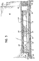
- FIG. 1 a sectional view of a reactor building having an arrangement of internal structures according to the invention.
- the reactor vessel 2 is disposed inside a confinement enclosure designated by the general reference 4.
- This enclosure consists of a cylindrical skirt 6, a raft 8, called general raft, and a dome (not shown) which closes the enclosure at its upper part.
- the tightness of the confinement enclosure 4 is ensured by a metallic coating 10 of mild steel also called skin.
- the lower part of the cylindrical skirt 6 is connected to the general raft 8.
- This connection can take the form of a frustoconical gusset 12 as shown in Figures l, 2, but can also be of cylindrical shape.
- the internal concrete structures are located in the confinement enclosure 4 and serve mainly as support for the components of the primary circuit. These structures are made up of a slab 16, said slab of internal structures, of a concrete cylinder 18, said tank well, support of the tank 2 of the reactor and located substantially in the center of the slab of internal structures 16, and casemates 20 arranged radiantly with respect to the well of tank 18 of which they are integral.
- the internal structures are generally separated from the containment. A seal 5, for example made of styrene, prevails between this enclosure and the internal structures.
- the slab of internal structures can be positioned in the containment in several different ways.
- the positioning is achieved by keying the central part of the apron of the internal structures on the general apron, this keying ensuring the relative blocking in the horizontal direction of said structures while allowing their free expansion.
- the general raft 8 comprises a circular step 46 projecting above this raft and covered by the sealing skin 10.
- the raft of the internal structures 16 has a facing circular housing 47 cooperating with the step 46 by a vertical circular ring 48. This produces a horizontal locking while allowing relative displacements verti cals of the rafts relative to each other.
- the slab of the internal structures 16 comprises a buton slab 22 separated from the latter by means of a horizontal joint 24 formed by a sliding product. This joint reigns in a crown from the tank well 18 between the slab 22 and the slab of the internal structures 16.
- the thickness of the buton slab 22 is dimensioned to the minimum compatible with the seismic forces to be transmitted in order to consequently limit the thrust of thermal origin of this slab on gusset 12.
- Figure 2 a partial sectional view showing the first embodiment.
- the general raft 8 the mild steel coating 10 which seals the containment 4, the concrete layer 11 for protecting the skin, as well as the channels 13 embedded in the layer of protection 11 to allow verification of the welds of the skin 10.
- connection 12 the lower part of the cylindrical skirt 6 of the containment to the general raft 8.
- the slab 22 comprises a central part 22a, located opposite the well of the tank, and a peripheral part 22b, locked against the gusset 12 of the containment.
- the buton slab 22 rests on the general raft only by a peripheral support crown 23 of relatively reduced width, which determines in the center of the crown 23 a circular surface 25 of the general raft 8 which is not in contact with the strike off internal structures 16.
- the space 33 is constituted by a compressible layer 32 disposed over the entire surface 25.
- a vinyl sheet 34 disposed above the compressible layer 32 provides protection during the execution of slab 22.
- the invention also relates to a method for producing the internal structures shown in FIG. 2.
- the general raft 8, the sealing coating 10 and the protective layer 11 of this coating are produced.
- the compressible layer 32 and its protective sheet 34 are placed on the annular surface 25 located between the support ring 23 and the part of the slab to the right of the tank well 18.
- the peripheral support ring 23 is concreted and then on the protective sheet 34 can either dispose of a lost formwork, or concrete a slab which will be self-supporting of the fresh concrete of the foundation of the internal structures.
- provisional wedges 36 are provided all around the surface located opposite the part 22a of the slab 22. The concreting continues. internal structures with the exception of the central part 22a which will be cast later.
- the wedges 36 can be deposited by means of jacks (not shown).
- the wedges and jacks are evacuated through the circular orifice which exists at this stage of the production of the internal structures in place of the central part 22a.
- a second compressible layer 38 is put in place on the general raft 8 with regard to the part 22a.
- a screed not reinforced with cement mortar 40 is produced on the compressible mattress 38. It is then possible to concret the part 22a of the slab. Pending reinforcements are provided at the base of the skirt of the tank well to secure the two structures.
- FIG. 3 a second embodiment of the invention.
- This embodiment includes pre-slabs 30 arranged over the entire surface 25, with the exception of the circle situated opposite the tank well 18. These pre-slabs 30 rest on the general raft by four support points 31. In this way, between the general raft 8 and the slabs 30, a free space 27 which is placed in communication with the atmosphere of the enclosure by a venting system 29.
- This arrangement makes it possible to balance, in the event of an accident, the pressure on either side of the raft of the internal structures 16.
- the effective pressure on the raft of the internal structures is zero and the pressure effect is transferred to the general raft 8.
- a compressible layer 32 made for example of polystyrene with vinyl protection has been placed over the entire surface of the floor slabs 30.
- the purpose of the compressible layer 32 is to absorb the relative deformations which tend to bring the general raft 8 closer to the raft of the internal structures 16 and thus perform the function of the space 33 described in the first embodiment.
- a vinyl sheet 34 placed above the compressible layer 32 provides protection during the execution of the buton slab 22.
- the invention also relates to a method for producing the internal structures shown in FIG. 3.
- the general raft 8, the mild steel sealing coating 10, and the protective layer 11 of this coating are produced.
- the slabs 30 are then placed on the annular surface delimited by the peripheral support ring 23 of the slab on the general raft outside, and inside, by the surface of the general raft situated opposite the part 22a. of the slab.
- the compressible layer 32 is placed on the pre-slabs 30, then a vinyl protective sheet 34 on the compressible layer 32.
- the peripheral support crown 23 is concreted.
- Wedges 36 are arranged all around the surface located opposite the part 22a of the slab, these wedges 36 temporarily installed with the aim of avoiding the exhaustion of the deformation capacity of the compressible layer 32 during the production of the internal structures.
- On the protective sheet 34 it is possible either to place a lost formwork or to concrete a slab which will be self-supporting from the fresh concrete of the slab 22. The concrete is then poured from the slab 22 with the exception of the central part 22a which will be cast later.
- the shims 36 can be deposited by means of jacks (not shown).
- the wedges and jacks are discharged through the circular orifice which exists at this stage of production of the internal structures, in place of the central part 22a.
- a second compressible layer 38 is put in place on the general raft 8 opposite the part 22a.
- a screed not reinforced with cement mortar 40 is produced on the compressible mattress 38. It is then possible to concret the part 22a of the slab. Pending reinforcements are provided at the base of the skirt of the tank well to secure the two structures.
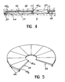
- the space 33 for decoupling the general raft and the internal structures is obtained by means of large slabs 42 in the form of circular sectors. These slabs have two support points 44 located at their periphery. They have no fulcrum at their central part 42a. Wedges 36, more particularly visible in Figure 4, act as support points during the production of internal structures, and this until they have acquired sufficient rigidity to be self-supporting of their own mass.
- the slabs 42 are arranged side by side as can be seen in Figure 5 so as to cover the entire annular surface located between the peripheral support ring 23 of the slab 22 and the surface of the general raft 8 located in look at the tank well.
- the free space 33 which, like the space 27 of the second embodiment, is placed in communication with the atmosphere of the confinement enclosure 4 by a venting system 29.
- the slabs 42 are rigid enough to support their own mass increased by that of concrete costs of the slab 22.
- the compressible layer 32 necessary in the case of the second embodiment does not exist, since the pre-slabs 42, unlike the pre-slabs 30, have no dots intermediate support and therefore do not transmit to the internal structures the deformations of the general raft 8.
- the compressible layer 38 located opposite the well of the vessel also exists in this third embodiment.
- the invention also relates to a method for producing the internal structures which have just been described with reference to FIGS. 4 and 5.
- the predales 42 are placed side by side, as shown in FIG. 5, on the surface of the general slab located between the peripheral support ring 23 of the slab 22 and the surface located opposite the tank well, the support shims 36 being arranged under the end 42a of the slabs 42.
- the structures are then started to be concreted with the exception of zone 22a located opposite the tank well.
- the wedges 36 are evacuated by means of jacks (not shown) through the central opening which still remains at this stage of the execution of the slab.
- Space 27 or 33 can be drained after an accident and is connected to the enclosure's scanning system by means of a tube embedded in the raft of the internal structures, the air being extracted by the venting ducts 29 ..
- the compressible layer is made of polystyrene
- this degradation does not present any particular disadvantage.
- the disappearance of the compressible layer even facilitates the proper functioning of the internal structures, in particular the independence of the deformations of the internal structures and the general raft.
- the venting system places the free space 27 or 33 fitted under the slabs at the pressure of the confinement enclosure 4. This pressure is transmitted to the lower surface of the raft of the internal structures by compression of the laminated formed by the slabs, the compressible layer and its non-reinforced protective screed when they exist (second embodiment), and possibly the buton slab 22, the horizontal joint 24 formed by a sliding product and its protective screed 26 with unreinforced cement mortar.
Landscapes
- Physics & Mathematics (AREA)
- Engineering & Computer Science (AREA)
- Plasma & Fusion (AREA)
- General Engineering & Computer Science (AREA)
- High Energy & Nuclear Physics (AREA)
- Buildings Adapted To Withstand Abnormal External Influences (AREA)
- Filling Or Discharging Of Gas Storage Vessels (AREA)
- Building Environments (AREA)
- Conveying And Assembling Of Building Elements In Situ (AREA)
Applications Claiming Priority (2)
| Application Number | Priority Date | Filing Date | Title |
|---|---|---|---|
| FR8025305 | 1980-11-28 | ||
| FR8025305A FR2495371A1 (fr) | 1980-11-28 | 1980-11-28 | Batiment reacteur comportant des structures internes dont les sollicitations sont independantes des deformations du radier general, et procede pour la realisation de ces structures internes |
Publications (2)
| Publication Number | Publication Date |
|---|---|
| EP0053553A1 true EP0053553A1 (de) | 1982-06-09 |
| EP0053553B1 EP0053553B1 (de) | 1985-03-27 |
Family
ID=9248462
Family Applications (1)
| Application Number | Title | Priority Date | Filing Date |
|---|---|---|---|
| EP81401878A Expired EP0053553B1 (de) | 1980-11-28 | 1981-11-26 | Reaktorgebäude mit inneren Strukturen, deren Beanspruchung unabhängig von der Formveränderung der Betonplatte sind, und Verfahren zum Herstellen dieser Strukturen |
Country Status (13)
| Country | Link |
|---|---|
| US (1) | US4476087A (de) |
| EP (1) | EP0053553B1 (de) |
| JP (1) | JPS57119294A (de) |
| KR (1) | KR880002048B1 (de) |
| DE (1) | DE3169598D1 (de) |
| EG (1) | EG19455A (de) |
| ES (1) | ES507526A0 (de) |
| FI (1) | FI72219C (de) |
| FR (1) | FR2495371A1 (de) |
| GR (1) | GR78024B (de) |
| MA (1) | MA19342A1 (de) |
| PT (1) | PT74008B (de) |
| YU (1) | YU42002B (de) |
Cited By (1)
| Publication number | Priority date | Publication date | Assignee | Title |
|---|---|---|---|---|
| FR2529006A1 (fr) * | 1982-06-18 | 1983-12-23 | Bbc Reaktor Gmbh | Installation de reacteur nucleaire |
Families Citing this family (2)
| Publication number | Priority date | Publication date | Assignee | Title |
|---|---|---|---|---|
| FR2469778A1 (fr) * | 1979-11-14 | 1981-05-22 | Framatome Sa | Installation de centrale nucleaire, et procede pour l'edification d'une telle centrale |
| JP2011247584A (ja) * | 2010-05-21 | 2011-12-08 | Toshiba Corp | 原子炉格納容器 |
Citations (4)
| Publication number | Priority date | Publication date | Assignee | Title |
|---|---|---|---|---|
| GB1086054A (en) * | 1963-05-13 | 1967-10-04 | Fairey Eng | Improvements relating to supporting platforms for nuclear reactors |
| DE1965850A1 (de) * | 1969-12-31 | 1971-07-08 | Siemens Ag | Deckelabdichtung fuer Spannbeton-Druckbehaelter |
| FR2214158A1 (en) * | 1973-01-11 | 1974-08-09 | Commissariat Energie Atomique | Nuclear reactor earthquake resistant support - with support points on a spherical convex surface |
| DE2346727A1 (de) * | 1973-09-17 | 1975-04-10 | Siemens Ag | Kernreaktoranlage |
Family Cites Families (8)
| Publication number | Priority date | Publication date | Assignee | Title |
|---|---|---|---|---|
| US3022238A (en) * | 1957-05-23 | 1962-02-20 | Kolflat Alf | Safety device for and method of protecting nuclear power plants |
| DE1207024B (de) * | 1961-06-14 | 1965-12-16 | Siemens Ag | Sicherheitseinrichtung fuer die Gebaeude von Leistungskernreaktoren |
| US3899391A (en) * | 1968-03-29 | 1975-08-12 | Stone & Webster Eng Corp | Containment vessel construction for nuclear power reactors |
| DE2320201A1 (de) * | 1973-04-19 | 1974-11-07 | Siemens Ag | Kernkraftwerk |
| US3986367A (en) * | 1975-10-01 | 1976-10-19 | Kalpins Alexandrs K | Earthquake-resistant anchoring system |
| US4053357A (en) * | 1975-12-03 | 1977-10-11 | Westinghouse Electric Corporation | Air box shock absorber for a nuclear reactor |
| CH619507A5 (de) * | 1977-03-21 | 1980-09-30 | Bbc Brown Boveri & Cie | |
| JPS54120384A (en) * | 1978-03-10 | 1979-09-18 | Toshiba Corp | Reactor containing device |
-
1980
- 1980-11-28 FR FR8025305A patent/FR2495371A1/fr active Granted
-
1981
- 1981-11-17 US US06/322,386 patent/US4476087A/en not_active Expired - Fee Related
- 1981-11-17 GR GR66548A patent/GR78024B/el unknown
- 1981-11-18 PT PT74008A patent/PT74008B/pt not_active IP Right Cessation
- 1981-11-25 YU YU2764/81A patent/YU42002B/xx unknown
- 1981-11-26 EP EP81401878A patent/EP0053553B1/de not_active Expired
- 1981-11-26 DE DE8181401878T patent/DE3169598D1/de not_active Expired
- 1981-11-27 JP JP56190475A patent/JPS57119294A/ja active Granted
- 1981-11-27 ES ES507526A patent/ES507526A0/es active Granted
- 1981-11-27 FI FI813819A patent/FI72219C/fi not_active IP Right Cessation
- 1981-11-27 KR KR1019810004599A patent/KR880002048B1/ko not_active Expired
- 1981-11-27 MA MA19546A patent/MA19342A1/fr unknown
- 1981-11-28 EG EG69781A patent/EG19455A/xx active
Patent Citations (4)
| Publication number | Priority date | Publication date | Assignee | Title |
|---|---|---|---|---|
| GB1086054A (en) * | 1963-05-13 | 1967-10-04 | Fairey Eng | Improvements relating to supporting platforms for nuclear reactors |
| DE1965850A1 (de) * | 1969-12-31 | 1971-07-08 | Siemens Ag | Deckelabdichtung fuer Spannbeton-Druckbehaelter |
| FR2214158A1 (en) * | 1973-01-11 | 1974-08-09 | Commissariat Energie Atomique | Nuclear reactor earthquake resistant support - with support points on a spherical convex surface |
| DE2346727A1 (de) * | 1973-09-17 | 1975-04-10 | Siemens Ag | Kernreaktoranlage |
Cited By (1)
| Publication number | Priority date | Publication date | Assignee | Title |
|---|---|---|---|---|
| FR2529006A1 (fr) * | 1982-06-18 | 1983-12-23 | Bbc Reaktor Gmbh | Installation de reacteur nucleaire |
Also Published As
| Publication number | Publication date |
|---|---|
| PT74008B (fr) | 1983-03-31 |
| EG19455A (fr) | 1995-09-30 |
| YU276481A (en) | 1983-12-31 |
| FR2495371B1 (de) | 1983-04-01 |
| FR2495371A1 (fr) | 1982-06-04 |
| GR78024B (de) | 1984-09-26 |
| JPH0250438B2 (de) | 1990-11-02 |
| FI72219B (fi) | 1986-12-31 |
| ES8600552A1 (es) | 1985-10-01 |
| US4476087A (en) | 1984-10-09 |
| KR830008345A (ko) | 1983-11-18 |
| YU42002B (en) | 1988-04-30 |
| FI813819L (fi) | 1982-05-29 |
| MA19342A1 (fr) | 1982-07-01 |
| EP0053553B1 (de) | 1985-03-27 |
| JPS57119294A (en) | 1982-07-24 |
| DE3169598D1 (en) | 1985-05-02 |
| FI72219C (fi) | 1987-04-13 |
| PT74008A (fr) | 1981-12-01 |
| KR880002048B1 (ko) | 1988-10-13 |
| ES507526A0 (es) | 1985-10-01 |
Similar Documents
| Publication | Publication Date | Title |
|---|---|---|
| EP0388253B1 (de) | Belade- und Sicherheitswasservorlagebecken für einen Druckwasserkernreaktor | |
| EP0373997B1 (de) | Lagerfass für radioaktive Abfälle | |
| EP0105800B1 (de) | Protektionsstruktur des Bodens einer Betonhülle | |
| EP3377795B1 (de) | Abdichtungsvorrichtung zwischen einem rohr und einer durch dieses rohr durchgehenden säule, verfahren zur montage davon | |
| EP0053553B1 (de) | Reaktorgebäude mit inneren Strukturen, deren Beanspruchung unabhängig von der Formveränderung der Betonplatte sind, und Verfahren zum Herstellen dieser Strukturen | |
| EP0258140A1 (de) | Fundament für Sicherheitsgebäude eines Kernreaktors | |
| EP0058601B1 (de) | Reaktorumschliessungsstruktur, wobei das Dach des umrandenden Gebäudes in der zylindrischen Wand des Sicherheitsbehälters eingebettet ist | |
| EP0055963B1 (de) | Flüssigmetallgekühlter Kernreaktor mit einem am Boden gekühlten Behälter | |
| FR2700801A1 (fr) | Réservoir enterré à enceinte étanche unique pour le confinement par exemple d'un gaz liquéfié, et agencement de tels réservoirs. | |
| JP3006292B2 (ja) | 吸引鋳造装置 | |
| JPS6223883Y2 (de) | ||
| US4028176A (en) | Nuclear reactor installation | |
| EP0156689B1 (de) | Schneller Kernreaktor mit hängendem Hauptbecken und Deckel | |
| EP0338894B1 (de) | Lagerfass für radioaktive Abfälle | |
| FR2589615A1 (fr) | Installation de reacteur nucleaire avec cuve de reacteur supportee par le bas | |
| EP0053552B1 (de) | Reaktorgebäude mit Kesselbehälter, dessen Rand mittels einer Betonplatte fixiert ist | |
| FR2705047A1 (fr) | Procédé et dispositif de soudage par faisceau d'électrons de deux pièces d'un composant de grande dimension et notamment d'un générateur de vapeur d'un réacteur nucléaire à eau sous pression. | |
| FR2615928A1 (fr) | Procede et installation destines a la mise en place d'une cuve de stockage de gaz sous pression, ainsi que la cuve adaptee | |
| EP4445018B1 (de) | Energiespeicher mit schwungrad und betongehäuse | |
| CN118911123A (zh) | 深基坑抗拔桩锚固结构及其施工方法 | |
| EP0130911B1 (de) | Abdichtungsanordnung für drehbare Deckelverschlüsse eines Kernreaktors | |
| FR2538152A1 (fr) | Couvercle etanche pour enceintes de reacteurs nucleaires | |
| FR2712004A1 (fr) | Plancher comportant une dalle en béton et procédé de construction s'y rapportant. | |
| JP2005289405A (ja) | タンク底部内側コーナ部構造及びその建造方法 | |
| JPH10280447A (ja) | 岩盤内高圧貯蔵施設 |
Legal Events
| Date | Code | Title | Description |
|---|---|---|---|
| PUAI | Public reference made under article 153(3) epc to a published international application that has entered the european phase |
Free format text: ORIGINAL CODE: 0009012 |
|
| AK | Designated contracting states |
Designated state(s): BE CH DE FR GB IT |
|
| 17P | Request for examination filed |
Effective date: 19821110 |
|
| ITF | It: translation for a ep patent filed | ||
| GRAA | (expected) grant |
Free format text: ORIGINAL CODE: 0009210 |
|
| AK | Designated contracting states |
Designated state(s): BE CH DE FR GB IT LI |
|
| REF | Corresponds to: |
Ref document number: 3169598 Country of ref document: DE Date of ref document: 19850502 |
|
| PLBE | No opposition filed within time limit |
Free format text: ORIGINAL CODE: 0009261 |
|
| STAA | Information on the status of an ep patent application or granted ep patent |
Free format text: STATUS: NO OPPOSITION FILED WITHIN TIME LIMIT |
|
| 26N | No opposition filed | ||
| ITTA | It: last paid annual fee | ||
| PGFP | Annual fee paid to national office [announced via postgrant information from national office to epo] |
Ref country code: BE Payment date: 19941031 Year of fee payment: 14 |
|
| PGFP | Annual fee paid to national office [announced via postgrant information from national office to epo] |
Ref country code: DE Payment date: 19941102 Year of fee payment: 14 |
|
| PGFP | Annual fee paid to national office [announced via postgrant information from national office to epo] |
Ref country code: GB Payment date: 19941111 Year of fee payment: 14 |
|
| PGFP | Annual fee paid to national office [announced via postgrant information from national office to epo] |
Ref country code: CH Payment date: 19941114 Year of fee payment: 14 |
|
| PGFP | Annual fee paid to national office [announced via postgrant information from national office to epo] |
Ref country code: FR Payment date: 19941129 Year of fee payment: 14 |
|
| PG25 | Lapsed in a contracting state [announced via postgrant information from national office to epo] |
Ref country code: GB Effective date: 19951126 |
|
| PG25 | Lapsed in a contracting state [announced via postgrant information from national office to epo] |
Ref country code: LI Effective date: 19951130 Ref country code: CH Effective date: 19951130 Ref country code: BE Effective date: 19951130 |
|
| BERE | Be: lapsed |
Owner name: FRAMATOME Effective date: 19951130 |
|
| REG | Reference to a national code |
Ref country code: CH Ref legal event code: PL |
|
| GBPC | Gb: european patent ceased through non-payment of renewal fee |
Effective date: 19951126 |
|
| PG25 | Lapsed in a contracting state [announced via postgrant information from national office to epo] |
Ref country code: FR Effective date: 19960731 |
|
| PG25 | Lapsed in a contracting state [announced via postgrant information from national office to epo] |
Ref country code: DE Effective date: 19960801 |
|
| REG | Reference to a national code |
Ref country code: FR Ref legal event code: ST |