EP0053575A1 - Débitmètre volumétrique à la manière d'un moteur à engrenage - Google Patents
Débitmètre volumétrique à la manière d'un moteur à engrenage Download PDFInfo
- Publication number
- EP0053575A1 EP0053575A1 EP81730115A EP81730115A EP0053575A1 EP 0053575 A1 EP0053575 A1 EP 0053575A1 EP 81730115 A EP81730115 A EP 81730115A EP 81730115 A EP81730115 A EP 81730115A EP 0053575 A1 EP0053575 A1 EP 0053575A1
- Authority
- EP
- European Patent Office
- Prior art keywords
- insert
- pole
- poles
- pole elements
- pins
- Prior art date
- Legal status (The legal status is an assumption and is not a legal conclusion. Google has not performed a legal analysis and makes no representation as to the accuracy of the status listed.)
- Granted
Links
- 230000000149 penetrating effect Effects 0.000 claims abstract description 9
- 239000004020 conductor Substances 0.000 claims abstract description 3
- 230000035515 penetration Effects 0.000 claims description 8
- 238000004026 adhesive bonding Methods 0.000 description 3
- 239000000463 material Substances 0.000 description 2
- 238000007789 sealing Methods 0.000 description 2
- 230000001154 acute effect Effects 0.000 description 1
- 230000006978 adaptation Effects 0.000 description 1
- XAGFODPZIPBFFR-UHFFFAOYSA-N aluminium Chemical compound [Al] XAGFODPZIPBFFR-UHFFFAOYSA-N 0.000 description 1
- 229910052782 aluminium Inorganic materials 0.000 description 1
- 230000015572 biosynthetic process Effects 0.000 description 1
- 230000001609 comparable effect Effects 0.000 description 1
- 238000006073 displacement reaction Methods 0.000 description 1
- 230000000694 effects Effects 0.000 description 1
- 239000012530 fluid Substances 0.000 description 1
- 230000004907 flux Effects 0.000 description 1
- 239000007788 liquid Substances 0.000 description 1
- 238000004519 manufacturing process Methods 0.000 description 1
- 230000035945 sensitivity Effects 0.000 description 1
Images


Classifications
-
- G—PHYSICS
- G01—MEASURING; TESTING
- G01F—MEASURING VOLUME, VOLUME FLOW, MASS FLOW OR LIQUID LEVEL; METERING BY VOLUME
- G01F3/00—Measuring the volume flow of fluids or fluent solid material wherein the fluid passes through the meter in successive and more or less isolated quantities, the meter being driven by the flow
- G01F3/02—Measuring the volume flow of fluids or fluent solid material wherein the fluid passes through the meter in successive and more or less isolated quantities, the meter being driven by the flow with measuring chambers which expand or contract during measurement
- G01F3/04—Measuring the volume flow of fluids or fluent solid material wherein the fluid passes through the meter in successive and more or less isolated quantities, the meter being driven by the flow with measuring chambers which expand or contract during measurement having rigid movable walls
- G01F3/06—Measuring the volume flow of fluids or fluent solid material wherein the fluid passes through the meter in successive and more or less isolated quantities, the meter being driven by the flow with measuring chambers which expand or contract during measurement having rigid movable walls comprising members rotating in a fluid-tight or substantially fluid-tight manner in a housing
- G01F3/10—Geared or lobed impeller meters
Definitions
- the invention relates to a volume flow sensor in the manner of a gear motor with a pair of round gear wheels, which are freely rotatable in a housing on fixed axes via ball bearings without wall contact and in which at least one non-magnetic insert is provided in a housing cover in the region of the teeth of the gear wheel , which is provided with two penetrating poles made of a magnetically highly conductive material, the inner ends of which lie essentially on the same gear wheel diameter and the outer ends of which are arranged with a field plate differential sensor with its field plates.
- the field plate differential sensor When a tooth passes by, the field plate differential sensor emits signals in the form of a sinusoidal signal with a positive and a negative period, from which pulse signals are derived, which are then in an impulse counter can be registered. Each pulse corresponds to an amount of fluid the size of the geometric tooth volume.
- Standard field plate differential sensors have two field plates with a plate area of 1 x 2 mm each. The long sides of these field plates are parallel to each other at a distance of 0.7 mm.
- the poles designed as pole pins in the non-magnetic insert are parallel to one another.
- the pole pins are offset in order to accommodate high internal pressures up to 400 bar. They have a diameter of 2.2 mm at their inner end and a diameter of 1.9 mm at their upper end with a center distance of 2.2 mm.
- Volume flow sensors of the known type produce useful sinusoidal signals up to a tooth size of approximately module 3. With volume flow sensors with gearwheels with a larger module, there are strong distortions of the sine curve with curve sections running at an acute angle to the zero line in the area of the zero crossing. No clean impulses can be derived from such distorted sine curves. In addition, there is a large deviation from the desired clock ratio 1: 1.
- the object of the invention is to design a volumetric flow sensor of the generic type such that a usable sinusoidal signal is emitted even in the case of gearwheels with a module> 3 when a tooth passes the differential field plate sensor.
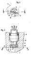
- the volume flow sensor shown in the drawing is constructed in the manner of a gear motor and has a pair of intermeshing gear wheels 2, which are freely rotatable on fixed axes 4 via ball bearings 6 in the chamber 8 accommodating them without touching the wall.
- the chamber 8 is formed in a lower housing part 10. It is closed by a cover 12.
- a seal 14 is arranged between the two housing parts. Bores 16 and 18 are arranged in the housing 10 at a distance from one another as inlet and outlet, via which the liquid enters and exits at the end face essentially parallel to the axes of rotation of the gear wheels.
- a field plate differential sensor 22 of a known type is arranged in a counterbore 20, which carries its two field plates at its lower end 24.
- An insert 28 made of an amagnetic material is inserted into the housing cover, starting from the inside 26 delimiting the chamber 8, and can be made in the form of a round plate made of aluminum or another amagnetic material. This plate lies coaxially with the bore 20.
- two pole pins 30, 32 are arranged at an angle ⁇ at an angle ⁇ to the common axis of insert 28 and field plate differential sensor 22, as shown in FIGS.
- the angle of inclination ⁇ can be, for example, 45 °.
- the pole pins 30 and 32 are arranged in two planes 36, 38 located at a distance a from one another. These levels are essentially parallel to each other.
- the pole pins penetrate the inside and outside of the insert 28 with elliptical cross sections, the ellipses with their long axes lying parallel to one another at the upper end opposite the field plates, the center points of the ellipses lying on a line 40 which runs essentially perpendicular to the planes 36 and 38 or the short axes of the ellipses are aligned with one another.
- the pole pins 30 and 32 can be offset in a known manner in order to transmit the internal pressure of the volume flow sensor to the insert 28. Such a stepped section is not shown in the drawing.
- the achievable minimum distance a of the pole pins no longer depends on the largest diameter of the pole pins.
- the center distance a of the pole pins at the inner ends opposite the field plates can thus be largely adapted to the center distance of the field plates of the field plate differential sensor.
- a pole pin diameter in this range of 1.5 to 1.6 mm a center distance corresponding to the center distance of commercially available field plate differential sensors of 1.7 mm can be exactly adjusted.
- the penetration ellipse of the pole pins 30 and 32 at the upper end of the insert 28 largely covers the field plate surface, so that the magnetic flux can pass from the sensor into the pole pins with high efficiency.
- the connecting line 40 is offset between the centers of the pole pins at their upper end against the connecting line 42 by the centers of the pole pins at the lower pole ends at an angle ⁇ *.
- the insert 28 is therefore to be inserted into the housing cover 12 in such a way that the two pole pins are essentially on the same through Knife of the gear 2 are in the region of its teeth, preferably on the pitch circle of the gears. A certain asymmetry occurs here, which can still lead to a slight distortion of the specified sine signals.
- two oppositely inclined bores 46, 48 are arranged in the insert 44, which are arranged at such an angle ⁇ to the outer surface 52 lying parallel to the inner surface 50 that they penetrate the edge 54 of the insert.
- pole pins 56 are arranged, which in the Boh stanchions can be glued.
- the pole pins can, as shown, be used as cylindrical pins, the radially outer ends lying radially inward from the penetration surface of the oblique bore.
- the end 58 of the pole pins penetrating the outer surface 52 is machined so that an elliptical penetration is formed in the outer surface, as in the embodiment according to FIGS. 3 and 4.
- holes 62, 64 are provided symmetrically to the center line 60 of the insert, which penetrate into the inclined pole pins 56 or cut them out.
- Cylindrical pole pins 66 are inserted into these bores and fixed by gluing.
- the protruding ends 68 of the pole pins 66 are machined down to the inner surface 50 of the insert. This can be done, for example, after inserting the insert into the housing cover 12 when processing the inside 26 thereof.
- the pole pins can of course also be fixed with a press fit in the holes.
- the inside of the pole pins 66 is circular.
- the inclined pole pins 56 can always be arranged at the same angle, while the distance between the inner pole pins 66 is selected according to the respective needs of the signal pickup. Since the inclined outer pole pins 56 are no longer acted upon in the axial direction of the volume flow sensor, they can be designed without a shoulder even at high internal pressures of the sensor. The inner pole pins 66 acted upon by the internal pressure are supported in the bottom of the blind bore and in this way secured against displacement.
- the insert 70 is provided with two parallel bores 72, 74, which in turn run essentially parallel to the inner surface 76 or outer surface 78 of the insert.
- the bores 72 and 74 can be designed as blind bores. However, as shown in the drawing, they preferably extend through the entire insert.
- pole pins 80, 82 are inserted into the bores 72 and 74 from opposite ends, which are fixed by gluing in the bore.
- blind holes 84, 86 are provided, as in the embodiment according to FIG. 5, which penetrate into the pole pins 80 and 82, respectively.
- cylindrical pole pins 88, 90 are fastened in a sealing manner in these bores.
- the lower half are provided in the center of the insert on a line transverse to the axes of the pole pins 80, 82, bores 92 which in turn penetrate into the pole pins 80, 82.
- Cylindrical pole pins 94 are inserted into these bores and fastened in a sealing manner.
- the penetration ellipse is omitted and in the outer surface, which leads to an advantageous overlap of the field plates of the field plate differential sensors in the embodiments according to FIGS. 1 to 5.
- a comparable effect can be achieved in that a correspondingly larger diameter is selected for the pole pins 94, as indicated in FIG. 7 below. Such a larger diameter is easily possible since the pole pin 94 is not subjected to pressure.
- FIG. 7 Such an embodiment is shown in Fig. 7 above.
- a central counterbore 96 is arranged, which cuts the horizontal pole pins 80 and 92 with a flat bottom surface.
- Pole pins 98 with a rectangular cross section can then be inserted into this bore, which can then be glued in the blind bore.
- the two pole pins 98 can be glued to an amagnetic middle layer 100 so that both pole pins can be used as one component.
- the thickness of the non-magnetic intermediate layer 100 can be selected precisely in accordance with the distance between the field plates and the rectangular cross section of the pole pins 98 in accordance with the cross section of the field plates.
- the diameter of the counterbore 96 is preferably chosen so that it forms the circumscribing circle for the pole pin element with an amagnetic intermediate layer, so that the pole pin element is centered in the counterbore.
- the dimensions can also be chosen so that a clamping effect occurs at the same time, the clamping can also be dimensioned such that an additional gluing can be omitted.
Landscapes
- Physics & Mathematics (AREA)
- Fluid Mechanics (AREA)
- General Physics & Mathematics (AREA)
- Transmission And Conversion Of Sensor Element Output (AREA)
Applications Claiming Priority (2)
| Application Number | Priority Date | Filing Date | Title |
|---|---|---|---|
| DE3045043 | 1980-11-27 | ||
| DE3045043 | 1980-11-27 |
Publications (2)
| Publication Number | Publication Date |
|---|---|
| EP0053575A1 true EP0053575A1 (fr) | 1982-06-09 |
| EP0053575B1 EP0053575B1 (fr) | 1984-08-08 |
Family
ID=6117901
Family Applications (1)
| Application Number | Title | Priority Date | Filing Date |
|---|---|---|---|
| EP81730115A Expired EP0053575B1 (fr) | 1980-11-27 | 1981-10-30 | Débitmètre volumétrique à la manière d'un moteur à engrenage |
Country Status (2)
| Country | Link |
|---|---|
| US (1) | US4409829A (fr) |
| EP (1) | EP0053575B1 (fr) |
Cited By (3)
| Publication number | Priority date | Publication date | Assignee | Title |
|---|---|---|---|---|
| EP0393294A1 (fr) * | 1989-04-17 | 1990-10-24 | Dopag Ag | Compteur de débit volumique |
| US7650800B2 (en) | 2004-06-04 | 2010-01-26 | Vse Volumentechnik Gmbh | Flow sensor and method for measuring the volume and/or flow speed of a medium |
| US7942070B2 (en) | 2004-06-04 | 2011-05-17 | Vse Volumentechnik Gmbh | Flow rate sensor |
Families Citing this family (11)
| Publication number | Priority date | Publication date | Assignee | Title |
|---|---|---|---|---|
| US4641522A (en) * | 1985-04-03 | 1987-02-10 | Lopresti William J | Bearing-less positive displacement flowmeter |
| US4911010A (en) * | 1988-08-12 | 1990-03-27 | Flowdata, Inc. | Fluid flowmeter |
| US5325715A (en) * | 1989-08-09 | 1994-07-05 | Flowdata, Inc. | Fluid flowmeter |
| US4996888A (en) * | 1989-08-09 | 1991-03-05 | Flowdata, Inc. | Fluid flowmeter |
| DE4040409C1 (fr) * | 1990-12-18 | 1992-05-14 | Vse Schweisstechnik Gmbh, 5982 Neuenrade, De | |
| DE4142062A1 (de) * | 1991-12-19 | 1993-07-01 | Salzkotten Tankanlagen | Vorrichtung zum messen von fluessigkeitsmengen in zapfsaeulen von kraftfahrzeug-tankstellen |
| EP0722044B1 (fr) * | 1995-01-11 | 2002-05-15 | Micropump Incorporated | Dispositif avec pompe et débitmètre intégrés |
| US5727933A (en) * | 1995-12-20 | 1998-03-17 | Hale Fire Pump Company | Pump and flow sensor combination |
| JP2002349507A (ja) * | 2001-05-31 | 2002-12-04 | Yasunaga Corp | アクチュエータ位置検出センサ及びこれを用いた油圧システム |
| EP1777515B1 (fr) * | 2006-07-21 | 2009-05-06 | Agilent Technologies, Inc. | Débitmètre avec dispositif de mesure et unité de commande |
| DE102012216817A1 (de) * | 2012-09-19 | 2014-03-20 | Nordson Corporation | Dosiereinrichtung für ein Fluid |
Citations (3)
| Publication number | Priority date | Publication date | Assignee | Title |
|---|---|---|---|---|
| FR1409036A (fr) * | 1964-09-10 | 1965-08-20 | Appareil de mesure de débit | |
| DE2157127A1 (de) * | 1970-11-19 | 1972-05-31 | Uzina De Fibre Sint Iasi | Elektronisches Zählsystem an Ovalradzählern bzw. -messern |
| DE2554466B2 (de) * | 1975-12-04 | 1978-05-03 | Kracht Pumpen- Und Motorenfabrik Gmbh & Co Kg, 5980 Werdohl | Durchflußmengenmeßgerät |
Family Cites Families (1)
| Publication number | Priority date | Publication date | Assignee | Title |
|---|---|---|---|---|
| US3166936A (en) * | 1960-04-27 | 1965-01-26 | Rockwell Mfg Co | Turbine flow meter |
-
1981
- 1981-10-30 EP EP81730115A patent/EP0053575B1/fr not_active Expired
- 1981-11-25 US US06/325,019 patent/US4409829A/en not_active Expired - Fee Related
Patent Citations (3)
| Publication number | Priority date | Publication date | Assignee | Title |
|---|---|---|---|---|
| FR1409036A (fr) * | 1964-09-10 | 1965-08-20 | Appareil de mesure de débit | |
| DE2157127A1 (de) * | 1970-11-19 | 1972-05-31 | Uzina De Fibre Sint Iasi | Elektronisches Zählsystem an Ovalradzählern bzw. -messern |
| DE2554466B2 (de) * | 1975-12-04 | 1978-05-03 | Kracht Pumpen- Und Motorenfabrik Gmbh & Co Kg, 5980 Werdohl | Durchflußmengenmeßgerät |
Cited By (3)
| Publication number | Priority date | Publication date | Assignee | Title |
|---|---|---|---|---|
| EP0393294A1 (fr) * | 1989-04-17 | 1990-10-24 | Dopag Ag | Compteur de débit volumique |
| US7650800B2 (en) | 2004-06-04 | 2010-01-26 | Vse Volumentechnik Gmbh | Flow sensor and method for measuring the volume and/or flow speed of a medium |
| US7942070B2 (en) | 2004-06-04 | 2011-05-17 | Vse Volumentechnik Gmbh | Flow rate sensor |
Also Published As
| Publication number | Publication date |
|---|---|
| EP0053575B1 (fr) | 1984-08-08 |
| US4409829A (en) | 1983-10-18 |
Similar Documents
| Publication | Publication Date | Title |
|---|---|---|
| EP0053575B1 (fr) | Débitmètre volumétrique à la manière d'un moteur à engrenage | |
| DE3642912C2 (fr) | ||
| DE3147208C2 (de) | Volumenstromsensor nach Art eines Zahnradmotors | |
| DE1294820B (de) | Stroemungsdrossel, bestehend aus mindestens einem Paar von koaxialen, nacheinander durchstroemten zylindrischen Wirbelkammern | |
| DE2932728C2 (de) | Rotationskolbenmaschine, insbesondere Motor | |
| DE2829425C3 (de) | Vorrichtung zum Messen von Beschleunigungen an schwingenden Körpern | |
| DE2804275A1 (de) | Kontaktfreie stellungsdrehmelder oder potentiometer | |
| DE2728689B2 (de) | Kurbelwellenlager, insbesondere für Brennkraftmaschinen | |
| DE1817454B2 (de) | Servosteuerventil | |
| EP1054237A2 (fr) | Capteur de la position angulaire | |
| DE2446416C3 (de) | DurchfluBmesser | |
| EP0106010A1 (fr) | Tachymètre | |
| DE2616767B2 (de) | Mehrfach-Bukkal-Röhrchen | |
| DE1913468B2 (de) | Drehzahlgebergenerator | |
| EP0491246A2 (fr) | Capteur du volume pour fluides | |
| DE2618300A1 (de) | Schraubenpumpe | |
| DE1728408C3 (de) | Verbindungswelle für Türgriffe einer Türverriegelungseinrichtung. Ausscheidung aus: 1553616 | |
| DE4034683C2 (fr) | ||
| DE2916500C2 (fr) | ||
| DE2734035C2 (de) | Hydraulisches Servoventil | |
| DE1919143A1 (de) | Linear veraenderlicher linearer Stroemungsmittelwiderstand | |
| DE20003512U1 (de) | Drehwinkelsensor | |
| DE8031813U1 (de) | Volumenstromsensor nach art eines zahnradmotors | |
| DE8031818U1 (de) | Volumenstromsensor nach art eines zahnradmotors | |
| DE2847945A1 (de) | Blutaustauschvorrichtung |
Legal Events
| Date | Code | Title | Description |
|---|---|---|---|
| PUAI | Public reference made under article 153(3) epc to a published international application that has entered the european phase |
Free format text: ORIGINAL CODE: 0009012 |
|
| AK | Designated contracting states |
Designated state(s): FR GB IT NL SE |
|
| 17P | Request for examination filed |
Effective date: 19820723 |
|
| ITF | It: translation for a ep patent filed | ||
| GRAA | (expected) grant |
Free format text: ORIGINAL CODE: 0009210 |
|
| AK | Designated contracting states |
Designated state(s): FR GB IT NL SE |
|
| ET | Fr: translation filed | ||
| PLBE | No opposition filed within time limit |
Free format text: ORIGINAL CODE: 0009261 |
|
| STAA | Information on the status of an ep patent application or granted ep patent |
Free format text: STATUS: NO OPPOSITION FILED WITHIN TIME LIMIT |
|
| 26N | No opposition filed | ||
| ITTA | It: last paid annual fee | ||
| PGFP | Annual fee paid to national office [announced via postgrant information from national office to epo] |
Ref country code: SE Payment date: 19941018 Year of fee payment: 14 Ref country code: GB Payment date: 19941018 Year of fee payment: 14 |
|
| PGFP | Annual fee paid to national office [announced via postgrant information from national office to epo] |
Ref country code: FR Payment date: 19941025 Year of fee payment: 14 |
|
| PGFP | Annual fee paid to national office [announced via postgrant information from national office to epo] |
Ref country code: NL Payment date: 19941031 Year of fee payment: 14 |
|
| EAL | Se: european patent in force in sweden |
Ref document number: 81730115.3 |
|
| PG25 | Lapsed in a contracting state [announced via postgrant information from national office to epo] |
Ref country code: GB Effective date: 19951030 |
|
| PG25 | Lapsed in a contracting state [announced via postgrant information from national office to epo] |
Ref country code: SE Effective date: 19951031 |
|
| PG25 | Lapsed in a contracting state [announced via postgrant information from national office to epo] |
Ref country code: NL Effective date: 19960501 |
|
| GBPC | Gb: european patent ceased through non-payment of renewal fee |
Effective date: 19951030 |
|
| PG25 | Lapsed in a contracting state [announced via postgrant information from national office to epo] |
Ref country code: FR Effective date: 19960628 |
|
| EUG | Se: european patent has lapsed |
Ref document number: 81730115.3 |
|
| NLV4 | Nl: lapsed or anulled due to non-payment of the annual fee |
Effective date: 19960501 |
|
| REG | Reference to a national code |
Ref country code: FR Ref legal event code: ST |