EP0053601A1 - Appareil pour le pliage en zigzag de fils droits, notamment pour des machines de fabrication de grillages diagonaux - Google Patents
Appareil pour le pliage en zigzag de fils droits, notamment pour des machines de fabrication de grillages diagonaux Download PDFInfo
- Publication number
- EP0053601A1 EP0053601A1 EP81890172A EP81890172A EP0053601A1 EP 0053601 A1 EP0053601 A1 EP 0053601A1 EP 81890172 A EP81890172 A EP 81890172A EP 81890172 A EP81890172 A EP 81890172A EP 0053601 A1 EP0053601 A1 EP 0053601A1
- Authority
- EP
- European Patent Office
- Prior art keywords
- rails
- wire
- wires
- bending
- rail
- Prior art date
- Legal status (The legal status is an assumption and is not a legal conclusion. Google has not performed a legal analysis and makes no representation as to the accuracy of the status listed.)
- Granted
Links
Images


Classifications
-
- B—PERFORMING OPERATIONS; TRANSPORTING
- B21—MECHANICAL METAL-WORKING WITHOUT ESSENTIALLY REMOVING MATERIAL; PUNCHING METAL
- B21F—WORKING OR PROCESSING OF METAL WIRE
- B21F1/00—Bending wire other than coiling; Straightening wire
- B21F1/04—Undulating
-
- B—PERFORMING OPERATIONS; TRANSPORTING
- B21—MECHANICAL METAL-WORKING WITHOUT ESSENTIALLY REMOVING MATERIAL; PUNCHING METAL
- B21F—WORKING OR PROCESSING OF METAL WIRE
- B21F27/00—Making wire network, i.e. wire nets
- B21F27/08—Making wire network, i.e. wire nets with additional connecting elements or material at crossings
- B21F27/10—Making wire network, i.e. wire nets with additional connecting elements or material at crossings with soldered or welded crossings
Definitions
- the invention relates to a device for zigzag-shaped bending parallel to one another in a plane of straight wires with the aid of rails which can be displaced transversely to the wire coulter and which carry wire deflecting pins at the appropriate intervals and are moved alternately in opposite directions transversely to this direction during a working movement in the wire feed direction by means of a control device .
- Devices of this type are required in particular for machines for the production of so-called diagonal grids, in which two groups of alternately oppositely zigzagged wires are produced, and two adjacent ones of these wires each on the facing and possibly even somewhat. overlapping wave crests are connected to each other.
- the rails carrying the deflection pins are arranged at equal angular intervals on the circumference of a roller and can be displaced parallel to the roller axis.
- the rail ends engaging cam tracks, several rails are shifted alternately in opposite directions so that the wires are gripped at intervals from opposite sides, put under tension and bent to an increasing extent zigzagging around the pins with sliding movement on the pins.
- each rail is articulated at one end of at least two equally long, parallel support arms pivoted about axes perpendicular to the bending plane, and that by means of the control device for each bending process only one rail, namely around the full amplitude of the desired zigzag shape and with simultaneous pivoting of its support arms can be moved.
- a relative rolling movement of the pin on the wire occurs with each bending operation due to the movement of the bending deflection pin and the adjacent piece of wire on a circular arc, which contains only a very small sliding component.
- this sliding component can be reduced even further and even made to disappear entirely by arranging the pivot axes of the support arms of each rail at least approximately in alignment with centers of nestling circles of those evolutees which have wire sections of a predetermined length tangent to deflection pins of successive rails to be discribed.
- the pivot axes of the support arms of the rails run radially to the roller according to the invention and are offset in the axial direction from rail to rail by half the division of the row of deflection pins.
- the pivot axes of the support arms of at least two rails are mounted in a component that can be moved back and forth in the wire feed direction, and the deflection pins of the rails can be removed from the bending plane at the end of a bending process, e.g. by pivoting or lifting the component carrying the rails in order to enable the rail-carrying component to move backwards after each bending operation.
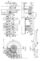
- a lower crossbeam 2 is arranged in a machine frame 1, along which dressage devices 3 are provided for the wires of a wire coulter 4.
- the dressage devices 6 for the wires of a second wire coulter 7 are arranged on a second, upper crossbar 5.
- the two wire shares 4 and? are drawn off from unwinding drums (not shown) via deflecting rollers 8, 9, guided from below or above into a common vertical plane and fed from there to a lattice manufacturing machine after being deformed by means of shaping rollers 15, 16.
- the deflection rollers 8, 9 have been omitted so as not to disturb the overview.
- two stands 13, 14 are arranged, in which the two form rollers 15, 16 are rotatably mounted.
- the drive for the forming rolls and all other elements of the machine is carried out by a motor 17 via gearwheels 18 only indicated.
- the wires of the two sets of wires 4 and 7 are deflected on the shaping rolls 15 and 16 assigned to them, each wire being bent in a zigzag shape along the circumference of the roll, as can be seen in FIG. 2 and will be explained in more detail later.
- the two zigzag-shaped wire coils created in this way, one of them along the circumference of the forming roller 16 and the other runs along the circumference of the shaping roller 15, are opposite one another at the end of their deflection path on the two shaping rollers in such a way that their mutually facing wave apices overlap to a small extent.
- the family of wire coils formed by the upper form roller 16 and the family of wire coils formed by the lower form roller 15 and drawn tangentially from the form rollers are guided into a common plane and between connecting tools of a lattice production machine, by means of which the mutually facing, somewhat overlapping Vertices of adjacent wire coils of the two shares are connected to one another, so that a grid with essentially rhombic meshes is formed.
- the roller electrodes 21, 22 are arranged at intervals and parallel to one another along shafts 23, 24 which are mounted in side disks 25, 26.
- the disks 25 are rigidly attached to a beam 27 extending across the machine width.
- the disks 26 are essentially triangular in shape and are each connected at one of their corner points via a joint 28 to a support 29 which in turn is fastened to a beam 30 which extends across the machine width.
- One of the bars 27 or 30 can also be designed to be adjustable in height by means which are not shown because generally known means in order to be able to adapt the distance between the roller electrodes 21, 22 to different wire diameters.
- each disc 26 is through a hinge 31 connected to an adjustable compression spring 32, by means of which the contact pressure of the roller electrodes 22 at the wire crossing points can be adjusted as required.
- the roller electrodes 22 are alternately connected to the two poles of the secondary side of welding transformers 34 by means of flexible feed lines 33.
- adjacent upper roller electrodes 22 are electrically insulated from one another, whereas the lower roller electrodes 21 are conductively connected to one another and thus form a passive current bridge.
- Gripping hooks 41, 42 which are attached to beams 43, 44 running across the width of the machine, carry out the lattice transport.
- the beams 43, 44 engage trunnions which are arranged at one end of one-armed levers 45, 46; the other ends of these one-armed levers are rotatably connected to shafts 47, 48.
- the shafts 47, 48 are set in reciprocating pivoting movements, in such a way that the end of the one-armed lever 45 carrying the bar 43 moves away from the roller electrodes 21, 22, while the one carrying the bar 44 moves End of the one-armed lever 46 moved to the roller electrodes 21, 22, and vice versa.
- the bars 43, 44 are pivoted about their longitudinal axes via two single-arm levers 49, 51 and a bumper 53, or via two single-arm levers 50, 52 and a bumper 54, the bar moving away from the roller electrodes 21, 22 in each case - in the working phase assumed above, the beam 43 is pivoted such that its gripping hooks 41 engage the mesh meshes, while at the same time the gripping hooks 42 of the other beam 44 are pivoted out of engagement with the mesh, and vice versa.
- the one-armed levers 51, 52 are rotatably attached to shafts 55, 56 arranges, which are set in reciprocating swiveling movements via cam drives.
- the drive of the actual deformation tools is removed from an eccentric 71 and transmitted from a connecting rod 72 to one arm of an angle lever 73, on the other arm of which a bumper 74 is articulated. 2, the bumper 74 is articulated to one arm of two further angle levers 75, 76, on the other arms of which the end of another bumper 77, 78 is articulated.
- the ends of the bumpers 77, 78 opposite the angle levers 75, 76 are articulated to the stand 13 by means of rockers 79, 80.
- the bumpers 77, 78 according to FIGS. 4 and 5 have components 81 acting as stops, which partially engage in a cam track 82 in the working position.
- a cam track 82 is located at both ends of each of the two molding rolls 15, 16, and the ends of rails 83 arranged along the circumference of the molding rolls 15, 16 come alternately, the one track with the cam track on the right side of the machine and the the next rail engages with the cam track on the left side of the machine, by means of guide rollers.
- Each of the rails 83, along which deflection pins 86 are provided at intervals for each wire, is articulated according to FIG. 3 to one end of at least two parallel, equally long support arms 84, the other ends of which are arranged radially in the shaping rollers 15, 16 and rotatable journal 85 are attached.
- the assigned angle lever For example, the angle lever 75 in Figure 4, a pivoting movement by which the bumper 77 together with its stop 81 is displaced in the direction and by the amount of the desired parallel displacement of the rail 83 corresponding to the deformation of the wire.
- the stop 81 of the bumper 77 detects the guide roller of the rail during this movement and brings it into its new position on the raised part of the cam track 82.
- One of the prerequisites for forcing the wires to deform without sliding along the spaced diverter pins 86 of one of the rails 83 is that only a single one of the rails 83 is always displaced parallel to itself during a given time interval the other rails are at rest.
- the parallel displacements of the individual rails must therefore take place successively and in each case by an amount which is equal to the amplitude of the desired zigzag shape of the wires, and moreover must take place during a period during which the shaping rollers 15, 16 pass through an angle which is equal to that fraction is a full circle, which results from dividing the full circle by the number of rails 83 arranged along the circumference of a shaping roller.
- the deformation region 82a of the cam track which also depends on the desired mesh shape, with the track sections lying in front of and behind it in the direction of rotation of the shaping rolls, encloses such a steep angle that this area of the cam track of the guide rollers of the rails 83 could not be run due to self-locking without the participation of the movable stops 81.
- This can be seen particularly clearly from the development of the cam track 82 shown in FIG. 6.
- a distance X can also be seen in FIG. 6 by which the stop 81 extends beyond the required amplitude is moved to take account of a spring back of the bent wire after relief by the deflection pins 86.
- the arms of the angle levers 75, 76 which actuate the bumpers 77, 78 and the rockers 79, 80 are arranged at an angle to one another in such a way that always those of these elements, on the side of which a stop 81 for parallel displacement a rail 83 operates, is pivoted from a rest position running at an acute angle to the circumferential plane of the shaping rollers 15, 16 into a working position parallel to this circumferential plane.
- a deflection pin 86a has moved from its initial position, not shown, to its end position shown in FIG. 7.
- the wire D gripped by this deflecting pin comes from one of the deflecting rollers 8, 9, touches the pin 86a at point T1 and partially wraps around it.
- the wire D is touched by the next deflecting pin 86b, which is still in its rest position Mb.
- points P1 to P3 must also lie on a conforming circle at the Evolute. This is the case when the deflection pin 86b is moved in a circular path around a point M which lies at the intersection of normals established in the centers of the chords P1-P2 and P2-P3.
- the axes of the journals 85 of the support arms 84 which support the rail 83 on which the deflection pins 86b are arranged, must therefore intersect the generatrix of the cylinder jacket of the forming roll on which the point M is located, and the axes of these support arms 84 must be at the moment the contact of the wires D through the journals 86b run parallel to the straight line M-Mb.
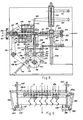
- FIGS. 1 to 7 show another embodiment of a device according to the invention.
- the actual bending process in this embodiment is based on the same principle as in the embodiment shown in FIGS. 1 to 7, but instead of the shaping rolls 15, 16 two bars 101, 102 are provided, which are parallel to the planes of movement of them in parallel planes supplied wire coulters 4, 7 are moved back and forth.
- At least two pairs of bearing journals 85 are provided on each of the two beams 101, 102, which in the same way as shown in FIGS. 3 to 5 carry rails 83 with deflection pins 86 on support arms 84.
- deflection pins 86 In addition to these movably arranged deflection pins 86, at least two rows of immovably fixed preferred pins 103 are arranged on each of the two beams 101, 102, which engage in already formed bending points of the wires of the wire shares 4, 7 and thereby the already deformed wires in converging guides 20 and advance through it to the welding station.
- the two beams 101, 102 are connected to one another by means of joints 105 and can be opened and closed pivoting about these joints like the jaws of a pair of pliers.
- joints 105 In the wire feed direction in front of the joints 105 of the bars 101, 102 there are automatic clamping devices 106, 107 - one for each wire to be fed - which, during the forward movement of the bars 101, 102, grasp the incoming wires of the wire shares 4, 7 and are not shown Pull off the reel, but slide the bars 101, 102 along the wires as you move them back without taking them with you.
- the entire drive is removed from a motor-driven shaft 110.
- a first cam disk 111 (FIG. 10) sits on this shaft 110 and actuates a one-armed lever 112 via a scanning roller 113.
- the one-armed lever 112 which is loaded by a return spring 114, is arranged in a rotationally fixed manner at the end of a shaft 115, along which two further one-armed levers 116 are wedged.
- the levers 116 engage with sliding blocks 117 in correspondingly shaped slots in the articulated region of the beams 101, 102 and give these beams the common forward and reverse movement mentioned.
- a spring-loaded angle lever 122 is actuated, which acts on a lever 124 via a bumper 123.
- the lever 124 is rotatably connected to a shaft 125, which is only indicated. Gears connected to a shaft parallel to it and cooperating with it.126 on rotation.
- the two shafts 125, 126 carry a number of one-armed levers 127, 128, which are provided with teeth 129, which engage laterally from electrodes 130, 131, before they come into effect, in the mesh and thereby the overlapping and for welding certain vertex areas of two zigzag bent, adjacent wires in the correct relative position to each other.
- the levers 127, 128 swivel back into their rest position and release the grid mesh for the further transport of the grid.
- the electrodes 130, 131 are designed as elongated rails in order to be able to detect two welding spots each from two adjacent wires to be welded, which overlap with their wave apices.
- the upper electrodes 130 are arranged in a known manner in an electrode bar 140 which extends and moves up and down over the machine width and is resiliently supported with respect thereto.
- the electrode bar 140 is articulated to two equally long, parallel, pivotably mounted levers 141, 142, of which the lever 142 extends beyond the electrode bar 140 and is connected by a joint 143 to a connecting rod 144, the other end of which is connected to an eccentric 145 is.
- the electrode bar 130 is placed on the grid mesh in the welding cycle and lifted off the mesh again.
- the electrodes 130 are conductively connected to one another, so that the entirety of the electrodes 130 forms a passive current bridge.
- the lower electrodes 131 are likewise arranged in a known manner along a machine-fixed bar 146 which extends across the machine width and are electrically insulated from this bar and also from one another.
- the individual electrodes are conductively connected to the secondary sides of transformers, not shown, via flexible feed lines 147.
- a third cam disc 150 interacts with two scanning rollers 151, 152. Each of these scanning rollers is at the end of a two-armed lever 153; 154 arranged, which is wedged between its two arms on a shaft 155 or 156. The ends of the two-armed levers 153, 154 opposite the scanning rollers 151, 152 are connected to one another via a compression spring 157.
- the cam disc 150 is shaped such that the levers 153, 154 are always pivoted by the same angular amounts and in the same direction.
- a one-armed lever 158 or 159 is connected, at the other end of which a bumper 160 or 161 is articulated.
- the other ends of these bumpers 160, 161 are each connected to one of the beams 101, 102 on the side opposite the joints 105. Since, when the levers 153, 154 rotate in the same direction, for example the bumper 160 moves downward, but the bumper 161 moves upward, this lever system causes the bars 101, 102 to open and close around the joints 105.
- the bumpers 160, 161 and the one-armed lever 116 must be parallel to one another in every movement phase of the beams 101, 102.
- cam disks 170, 171 are provided on the shaft 110, which cooperate with scanning rollers 172, 173, which are shown in FIG. 8 lie in alignment with the scanning roller 152.
- These scanning rollers are articulated on the lower ends of two-armed levers 174, 175, of which the lever 174 is freely rotatably mounted on the shaft 156, whereas the lever 175 is mounted on its own shaft 176.
- Bumpers 177, 178 are articulated on the arms of the levers 174, 175 opposite the rollers 172, 173, which are connected to shafts 181, 182 according to FIG. 9 via levers 179, 180.
- Components 183, 184 designed as control levers are connected in a rotationally fixed manner to the upper ends of the shafts 181, 182 and move the rails 83 from their rest position into their working position in order to carry out bending operations.
- the control levers 183, 184 act against the rails 83 loaded by springs (not shown). These springs then also cause the rails 83 and the control levers 183, 184 and their entire drive system to be reset as soon as the cams 170, 172 reset the control levers 183, Allow 184.
- This last-described system thus takes over the function of the stops 81 and the cam tracks 82 of the embodiment of the invention shown in FIGS. 4 and 5.
- This device works as follows: as soon as a feed and bending step has been completed, the levers 127, 128 swivel into the working position, the teeth 129 engage in the crest of adjacent wires located in the welding area and center them so that the crest of the adjacent wires - from each of which one of the wire coulters 4 and the other of the wire coulters 7 belong - overlap by a predetermined amount.
- the eccentrics 145 now move the connecting rods 144 downward, as a result of which the electrode bar 140 articulated on the levers 141, 142 is also moved downward and the electrodes 130 are pressed against the weld metal. After switching on the welding current, a welding is carried out.
- the elements 150 to 161 are actuated in such a way that the beams 101, 102 are pivoted in opposite directions about the joints 105, moving away from one another.
- the preferred pins 103, 104 and the deflection pins 86 disengage from the already bent wires of the wire shares 4 and 7.
- the elements 112 to 117 cause the relaxing spring 114 to move the bars 101, 102 in FIG. 8 from right to left, whereby the clamps 106, 107 slide along the wires of the wire shares 4 and 7, so to speak, in idle mode.
- control levers 183, 184 are controlled via the elements 170 to 175 and 177 to 182 in such a way that they can yield to the action of the springs loading the rails 83 and thus return the rails 83 to their rest position allow.
- the elements 150 to 161 again cause the bars 101, 102 to close again by means of a pivoting movement about the joints 105 opposite to the first mentioned.
- the preferred pins 103, 104 engage in the already formed wave crests of the wires and those in the rest position located deflection pins 82 come to lie laterally next to the wires that are currently tapering and assigned to them.
- the teeth 129 are disengaged from the grid by the action of the elements 120 to 127 and at the same time the electrodes 130 are also raised above the elements 140 to 145 and now give in turn, the grid is free again.
- the elements 112 to 117 now begin to move the bars 101, 102 in FIG. 8 from left to right.
- the clamping devices 106, 107 grip the incoming wires and take them with them as they move.
- the already formed wave crests of the Preferred pins 103, 104 engaging wires advance the already bent wires through the guide 20 to the welding station.
- the control lever 184 is activated via the evenly numbered elements 172 to 182 and then, starting from the cam disc 171, the control lever 183 is activated via the odd numbered elements 173 to 181.
- devices according to the invention can also be used for producing support infills and the like. be used.
- any other type of connection of the overlapping vertices of the deformed wires can also be used, for example by gluing, by connection by means of clamping elements or the like.
Landscapes
- Engineering & Computer Science (AREA)
- Mechanical Engineering (AREA)
- Wire Processing (AREA)
- Bending Of Plates, Rods, And Pipes (AREA)
Applications Claiming Priority (2)
| Application Number | Priority Date | Filing Date | Title |
|---|---|---|---|
| AT5885/80 | 1980-12-02 | ||
| AT0588580A AT372632B (de) | 1980-12-02 | 1980-12-02 | Vorrichtung zum zickzackfoermigen biegen gerader draehte, insbesondere fuer maschinen zum herstellen von diagonalgittern |
Publications (2)
| Publication Number | Publication Date |
|---|---|
| EP0053601A1 true EP0053601A1 (fr) | 1982-06-09 |
| EP0053601B1 EP0053601B1 (fr) | 1984-08-01 |
Family
ID=3580606
Family Applications (1)
| Application Number | Title | Priority Date | Filing Date |
|---|---|---|---|
| EP81890172A Expired EP0053601B1 (fr) | 1980-12-02 | 1981-10-20 | Appareil pour le pliage en zigzag de fils droits, notamment pour des machines de fabrication de grillages diagonaux |
Country Status (6)
| Country | Link |
|---|---|
| US (1) | US4444227A (fr) |
| EP (1) | EP0053601B1 (fr) |
| JP (2) | JPS57118838A (fr) |
| AT (1) | AT372632B (fr) |
| DD (1) | DD201859A5 (fr) |
| DE (1) | DE3165254D1 (fr) |
Cited By (2)
| Publication number | Priority date | Publication date | Assignee | Title |
|---|---|---|---|---|
| EP0919309A3 (fr) * | 1997-11-27 | 2000-06-14 | Häussler Planung GmbH | Procédé et dispoditif pour la fabrication de treillis d'armature enroulés |
| CN113020347A (zh) * | 2021-03-09 | 2021-06-25 | 广东铭利达科技有限公司 | 一种数控弯管机 |
Families Citing this family (6)
| Publication number | Priority date | Publication date | Assignee | Title |
|---|---|---|---|---|
| JPS60142511A (ja) * | 1983-12-29 | 1985-07-27 | 株式会社村田製作所 | 蛇行状リ−ド線の成形方法およびその装置 |
| AT379973B (de) * | 1984-01-13 | 1986-03-25 | Evg Entwicklung Verwert Ges | Nach der elektrischen widerstandsmethode arbeitende gitterschweissmaschine |
| AT383292B (de) * | 1985-07-18 | 1987-06-10 | Evg Entwicklung Verwert Ges | Vorrichtung zum kontinuierlichen vorschieben und lagenrichtigen festhalten der drahtschar im schweissbereich einer schweissmaschine zum herstellen von diagonalgittern |
| DE4007204A1 (de) * | 1990-03-07 | 1991-09-12 | Otto Bihler | Bearbeitungsmaschine, insbesondere stanz- und biegeautomat stichwort: bearbeitungsmaschine mit stangensteuerung |
| US20070095006A1 (en) * | 2005-11-01 | 2007-05-03 | Konersmann Ronald D | Lightweight portable concrete enclosure and associated method of construction |
| CN116571648A (zh) * | 2023-04-10 | 2023-08-11 | 芜湖勤惠科技有限公司 | 一种用于自动化生产线的上下料输送设备 |
Citations (3)
| Publication number | Priority date | Publication date | Assignee | Title |
|---|---|---|---|---|
| US1908050A (en) * | 1929-09-19 | 1933-05-09 | Reed William Edgar | Apparatus for making wire fabric |
| FR1075191A (fr) * | 1952-10-21 | 1954-10-13 | Procédé et machine pour la fabrication de grillages | |
| AT317646B (de) * | 1972-07-17 | 1974-09-10 | Klaus Keller Dipl Ing | Vorrichtung zum Biegen von Strebenschlangen |
Family Cites Families (3)
| Publication number | Priority date | Publication date | Assignee | Title |
|---|---|---|---|---|
| US755006A (en) * | 1903-05-20 | 1904-03-22 | Alfred W Smith | Wire-clamping device. |
| US2868236A (en) * | 1953-11-02 | 1959-01-13 | W F And John Barnes Company | Apparatus for making wire articles |
| AT365491B (de) * | 1979-06-12 | 1982-01-25 | Evg Entwicklung Verwert Ges | Elektrodenanordnung an einer gitterschweissmaschine |
-
1980
- 1980-12-02 AT AT0588580A patent/AT372632B/de not_active IP Right Cessation
-
1981
- 1981-10-20 EP EP81890172A patent/EP0053601B1/fr not_active Expired
- 1981-10-20 DE DE8181890172T patent/DE3165254D1/de not_active Expired
- 1981-11-10 US US06/320,011 patent/US4444227A/en not_active Expired - Fee Related
- 1981-11-24 DD DD81235093A patent/DD201859A5/de unknown
- 1981-12-02 JP JP56192991A patent/JPS57118838A/ja active Granted
-
1988
- 1988-11-24 JP JP63294840A patent/JPH01284444A/ja active Granted
Patent Citations (3)
| Publication number | Priority date | Publication date | Assignee | Title |
|---|---|---|---|---|
| US1908050A (en) * | 1929-09-19 | 1933-05-09 | Reed William Edgar | Apparatus for making wire fabric |
| FR1075191A (fr) * | 1952-10-21 | 1954-10-13 | Procédé et machine pour la fabrication de grillages | |
| AT317646B (de) * | 1972-07-17 | 1974-09-10 | Klaus Keller Dipl Ing | Vorrichtung zum Biegen von Strebenschlangen |
Cited By (2)
| Publication number | Priority date | Publication date | Assignee | Title |
|---|---|---|---|---|
| EP0919309A3 (fr) * | 1997-11-27 | 2000-06-14 | Häussler Planung GmbH | Procédé et dispoditif pour la fabrication de treillis d'armature enroulés |
| CN113020347A (zh) * | 2021-03-09 | 2021-06-25 | 广东铭利达科技有限公司 | 一种数控弯管机 |
Also Published As
| Publication number | Publication date |
|---|---|
| AT372632B (de) | 1983-10-25 |
| DE3165254D1 (en) | 1984-09-06 |
| JPH01284444A (ja) | 1989-11-15 |
| US4444227A (en) | 1984-04-24 |
| ATA588580A (de) | 1983-03-15 |
| DD201859A5 (de) | 1983-08-17 |
| JPH0317572B2 (fr) | 1991-03-08 |
| EP0053601B1 (fr) | 1984-08-01 |
| JPH0119982B2 (fr) | 1989-04-13 |
| JPS57118838A (en) | 1982-07-23 |
Similar Documents
| Publication | Publication Date | Title |
|---|---|---|
| EP0023898B1 (fr) | Machine pour la fabrication automatique de poutres en treillis soudées | |
| DE3015846A1 (de) | Verfahren und vorrichtung zum automatischen positionieren der enden von drahtabschnitten | |
| DE69202679T2 (de) | Biege-Schermaschine mit mehreren Arbeitsebenen. | |
| EP0241449B1 (fr) | Machine à souder par résistance par points nombreuses | |
| AT413956B (de) | Schweissmaschine zum herstellen von drahtgittermatten | |
| EP0053601B1 (fr) | Appareil pour le pliage en zigzag de fils droits, notamment pour des machines de fabrication de grillages diagonaux | |
| WO2000043140A1 (fr) | Cintreuse | |
| EP0222140B1 (fr) | Méthode et dispositif pour plier un nombre de conducteurs électriquement isolés en forme de barreaux juxtaposés et/ou superposés | |
| DE2048855C3 (de) | Verfahren und Vorrichtung zum Herstellen von aus zwei parallelen Längsstäben und sprossenartig zwischengeschweiBten Querverbindern bestehenden Bauelementen aus Stahl | |
| DE2113196C3 (de) | Verfahren und Maschine zum Herstellen von Drahtgittern durch Reibungsschweißen | |
| DE4117955A1 (de) | Vorrichtung zum biegen von buegeln aus betonstahl | |
| EP0677343B1 (fr) | Procédé et appareil pour la production de châssis de coffrage | |
| EP1064108A2 (fr) | Cintreuse | |
| DE2825151A1 (de) | Vorrichtung zum intermittierenden bilden einer drahtflechte aus einem ohne unterbrechung zugefuehrten einzeldraht | |
| EP0313760B1 (fr) | Appareil pour fabriquer des poutres de construction ou similaires | |
| DE3341714C2 (fr) | ||
| AT401485B (de) | Verfahren und maschine zum herstellen von drahtgittern | |
| EP1450970A1 (fr) | Procede de production de grillages metalliques | |
| DE2414530C3 (de) | Verfahren und Vorrichtung zum Herstellen von gitterartigen Flächenbewehrungen | |
| DE19508207A1 (de) | Rollenschneid- und Wickelmaschine | |
| DE3406515C2 (fr) | ||
| DE4420231C1 (de) | Biegeeinrichtung zum zickzackförmigen Biegen von Verbindungsdrähten für Gitterträger | |
| DE69006712T2 (de) | Verfahren zum Binden von Packungen von metallischem Gitterwerk und Vorrichtung zur Durchführung dieses Verfahrens. | |
| DE2135029C3 (de) | Vorrichtung zum Schränken der Zähne von Sägeblättern | |
| CH615375A5 (fr) |
Legal Events
| Date | Code | Title | Description |
|---|---|---|---|
| PUAI | Public reference made under article 153(3) epc to a published international application that has entered the european phase |
Free format text: ORIGINAL CODE: 0009012 |
|
| AK | Designated contracting states |
Designated state(s): BE CH DE FR GB IT NL |
|
| 17P | Request for examination filed |
Effective date: 19820528 |
|
| ITF | It: translation for a ep patent filed | ||
| GRAA | (expected) grant |
Free format text: ORIGINAL CODE: 0009210 |
|
| AK | Designated contracting states |
Designated state(s): BE CH DE FR GB IT LI NL |
|
| REF | Corresponds to: |
Ref document number: 3165254 Country of ref document: DE Date of ref document: 19840906 |
|
| ET | Fr: translation filed | ||
| PLBE | No opposition filed within time limit |
Free format text: ORIGINAL CODE: 0009261 |
|
| STAA | Information on the status of an ep patent application or granted ep patent |
Free format text: STATUS: NO OPPOSITION FILED WITHIN TIME LIMIT |
|
| 26N | No opposition filed | ||
| PGFP | Annual fee paid to national office [announced via postgrant information from national office to epo] |
Ref country code: FR Payment date: 19900928 Year of fee payment: 10 |
|
| PGFP | Annual fee paid to national office [announced via postgrant information from national office to epo] |
Ref country code: GB Payment date: 19901010 Year of fee payment: 10 |
|
| ITTA | It: last paid annual fee | ||
| PGFP | Annual fee paid to national office [announced via postgrant information from national office to epo] |
Ref country code: NL Payment date: 19901031 Year of fee payment: 10 |
|
| PGFP | Annual fee paid to national office [announced via postgrant information from national office to epo] |
Ref country code: DE Payment date: 19901228 Year of fee payment: 10 |
|
| PG25 | Lapsed in a contracting state [announced via postgrant information from national office to epo] |
Ref country code: GB Effective date: 19911020 |
|
| PG25 | Lapsed in a contracting state [announced via postgrant information from national office to epo] |
Ref country code: NL Effective date: 19920501 |
|
| NLV4 | Nl: lapsed or anulled due to non-payment of the annual fee | ||
| GBPC | Gb: european patent ceased through non-payment of renewal fee | ||
| PG25 | Lapsed in a contracting state [announced via postgrant information from national office to epo] |
Ref country code: FR Effective date: 19920630 |
|
| PG25 | Lapsed in a contracting state [announced via postgrant information from national office to epo] |
Ref country code: DE Effective date: 19920701 |
|
| REG | Reference to a national code |
Ref country code: FR Ref legal event code: ST |
|
| PGFP | Annual fee paid to national office [announced via postgrant information from national office to epo] |
Ref country code: CH Payment date: 19930922 Year of fee payment: 13 |
|
| PGFP | Annual fee paid to national office [announced via postgrant information from national office to epo] |
Ref country code: BE Payment date: 19931112 Year of fee payment: 13 |
|
| PG25 | Lapsed in a contracting state [announced via postgrant information from national office to epo] |
Ref country code: LI Effective date: 19941031 Ref country code: CH Effective date: 19941031 Ref country code: BE Effective date: 19941031 |
|
| BERE | Be: lapsed |
Owner name: EVG ENTWICKLUNGS- U VERWERTUNGS- G.M.B.H. Effective date: 19941031 |
|
| REG | Reference to a national code |
Ref country code: CH Ref legal event code: PL |