EP0053637A1 - Répéteur optique appliqué dans des coupleurs de bus de données actives à canaux multiples pour fibres optiques - Google Patents
Répéteur optique appliqué dans des coupleurs de bus de données actives à canaux multiples pour fibres optiques Download PDFInfo
- Publication number
- EP0053637A1 EP0053637A1 EP80201167A EP80201167A EP0053637A1 EP 0053637 A1 EP0053637 A1 EP 0053637A1 EP 80201167 A EP80201167 A EP 80201167A EP 80201167 A EP80201167 A EP 80201167A EP 0053637 A1 EP0053637 A1 EP 0053637A1
- Authority
- EP
- European Patent Office
- Prior art keywords
- data bus
- circuit
- signals
- couplers
- receiver
- Prior art date
- Legal status (The legal status is an assumption and is not a legal conclusion. Google has not performed a legal analysis and makes no representation as to the accuracy of the status listed.)
- Granted
Links
Images




Classifications
-
- G—PHYSICS
- G02—OPTICS
- G02B—OPTICAL ELEMENTS, SYSTEMS OR APPARATUS
- G02B6/00—Light guides; Structural details of arrangements comprising light guides and other optical elements, e.g. couplings
- G02B6/24—Coupling light guides
- G02B6/36—Mechanical coupling means
- G02B6/3628—Mechanical coupling means for mounting fibres to supporting carriers
-
- G—PHYSICS
- G02—OPTICS
- G02B—OPTICAL ELEMENTS, SYSTEMS OR APPARATUS
- G02B6/00—Light guides; Structural details of arrangements comprising light guides and other optical elements, e.g. couplings
- G02B6/24—Coupling light guides
- G02B6/26—Optical coupling means
- G02B6/28—Optical coupling means having data bus means, i.e. plural waveguides interconnected and providing an inherently bidirectional system by mixing and splitting signals
- G02B6/2804—Optical coupling means having data bus means, i.e. plural waveguides interconnected and providing an inherently bidirectional system by mixing and splitting signals forming multipart couplers without wavelength selective elements, e.g. "T" couplers, star couplers
- G02B6/2808—Optical coupling means having data bus means, i.e. plural waveguides interconnected and providing an inherently bidirectional system by mixing and splitting signals forming multipart couplers without wavelength selective elements, e.g. "T" couplers, star couplers using a mixing element which evenly distributes an input signal over a number of outputs
-
- G—PHYSICS
- G02—OPTICS
- G02B—OPTICAL ELEMENTS, SYSTEMS OR APPARATUS
- G02B6/00—Light guides; Structural details of arrangements comprising light guides and other optical elements, e.g. couplings
- G02B6/24—Coupling light guides
- G02B6/36—Mechanical coupling means
- G02B6/3628—Mechanical coupling means for mounting fibres to supporting carriers
- G02B6/3632—Mechanical coupling means for mounting fibres to supporting carriers characterised by the cross-sectional shape of the mechanical coupling means
- G02B6/3636—Mechanical coupling means for mounting fibres to supporting carriers characterised by the cross-sectional shape of the mechanical coupling means the mechanical coupling means being grooves
-
- G—PHYSICS
- G02—OPTICS
- G02B—OPTICAL ELEMENTS, SYSTEMS OR APPARATUS
- G02B6/00—Light guides; Structural details of arrangements comprising light guides and other optical elements, e.g. couplings
- G02B6/24—Coupling light guides
- G02B6/36—Mechanical coupling means
- G02B6/3628—Mechanical coupling means for mounting fibres to supporting carriers
- G02B6/3664—2D cross sectional arrangements of the fibres
- G02B6/3672—2D cross sectional arrangements of the fibres with fibres arranged in a regular matrix array
-
- G—PHYSICS
- G02—OPTICS
- G02B—OPTICAL ELEMENTS, SYSTEMS OR APPARATUS
- G02B6/00—Light guides; Structural details of arrangements comprising light guides and other optical elements, e.g. couplings
- G02B6/24—Coupling light guides
- G02B6/36—Mechanical coupling means
- G02B6/3628—Mechanical coupling means for mounting fibres to supporting carriers
- G02B6/3684—Mechanical coupling means for mounting fibres to supporting carriers characterised by the manufacturing process of surface profiling of the supporting carrier
Definitions
- This invention relates to optical transmission medium data bus couplers and more particularly to active multiport optical conductor data bus couplers.
- Fiber optic buses offer several advantages over conven-- tional wire data buses. Large signal bandwidths and immunity to electromagnetic interference are well known properties of fiber optic cables. Further attributes include: freedom from disabling short circuits and intermittent connections; complete electrical isolation of interconnected systems; safety in explosive environments; light weight, and potential low cost.
- a third configuration termed hybrid configuration provides for more convenient interconnection by the strategic location of a multiport coupler in each main equipment center and by interconnection of couplers with a single harness.
- the loss between terminals in the aforementioned hybrid configuration is at best 5 to 7 db greater than the loss in a star configuration having the same number of terminals.
- an active multiport fiber optic data bus coupler in which selected incoming signals are optically isolated from the receiver of an associated repeater. More particularly, the present system embodiment comprises a first mixer which accepts inputs from a plurality of local transmitters and divides its output into a first portion that is supplied to an active receiver with its associated repeaters, and a second portion that is supplied to a second mixer which also accepts inputs from other couplers and combines the signals for outputing to a plurality of local receivers.
- active multiport fiber optic data bus coupler 88 of Figure 1 (and Figure 5 showing a connect- orized version of Figure 1) it will be observed that selected input signals 111 (three are shown ) are optically isolated from receiver 91 of optical repeater 93. More particularly, active multiport fiber optic data bus coupler 88 comprises first mixer 89 which is responsive to a plurality of input signals 101 from a plurality.of local transmitters (not shown) and divides its output into first output signals 103 via output fibers 105 (shown in Figure 1 as parallel lines so as to increase the signal to noise ratio) to receiver 91 of optical repeater 93, and second output signals 105 coupled to provide input signals to second mixer 90.
- first mixer 89 which is responsive to a plurality of input signals 101 from a plurality.of local transmitters (not shown) and divides its output into first output signals 103 via output fibers 105 (shown in Figure 1 as parallel lines so as to increase the signal to noise ratio) to receiver 91 of optical repeater 93, and second output signals 105 coupled
- Second mixer 90 is also responsive to input signals 111 from other couplers (not shown) combining these signals and providing output signals 113 via output fibers from second mixer 90 to local receivers (not shown).
- Optical transmitter 92 (seen in more detail in Figure 5 to include a plurality of signal sources denoted T ) output signals 115 are transmitted to other couplers 88 (not shown in Figure 1 but shown in the data bus arrangement of Figure 4).
- Coupler 88 distributes signals from local transmitters and also incoming signals from other couplers to the local receivers. A portion 105 of the signal from local transmitters is tapped off to optical repater 93, which boosts the signal level prior to transmission to other couplers.
- optical transmission lines carrying incoming signals from other couplers are optically isolated (by about 23 db optical) from receiver 91 of optical repeater 93 by first and second mixers 89 and 90.
- coupler 88 of figure 1 signals 111 from other couplers are coupled as inputs to second mixer 90 downstream from output signals 103 coupled as inputs to optical repeater 93. Isolation of receiver 91 from signals originating from other couplers is essential in avoiding race conditions. Preliminary calculations indicated that the desired signal (to be repeated) to undesired signal(not to be repeated) of an optical 21 db would result from this configuration which is more than sufficient for high quality reception and the prevention of race conditions. Power equalization is inherent in this embodiment since signals from other couplers are received at nearly the same signal level as signals from local transmitters, any small difference occurring due to coupler power splitting and line losses being easily compensated for by adjustment of repeater transmitter levels.
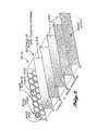
- Optical mixers 89 and 90 are optical waveguides whose function is to accept optical power at any point on their input and distribute it uniformly over their output and my comprise an exemplary component.such as shown in figure 2 (with appropriate legends shown for clarity).
- Optical mixers 89 and 90 include a core of optically conducting material surrounded over their lengths by a material having a lower index of refraction than the core material so that light entering the mixers input is substantially completely reflected off the sides.
- the shape of the mixer is an important factor in determining the degree of uniformity that power is distributed over the mixers output. For example, skew rays injected into cylindrical type mixers (not shown) tend to follow helical paths which never pass through the center of the mixer.
- Optical repeater 93 of figure 1 is shown in detailed schematic form in figures 1A andB and generally comprises means for detecting a low level optical signal, amplifying the signal, discriminating between signals to be repeated (or regenerated) and undesired noise or other signals, and generation of the desired data bus waveform optical output signal or signals.
- optical repeater 93 includes input device 401 comprising a photo detector connected in series circuit with the base electrode of low noise transistor 403 (a type 2N 3117).
- Output fibers 105 from first mixer 89 (shown in Figure 1) provide the input to photo detector 401. All three of fibers 105 carry the same signal and three however are used since the combined power will result in a higher signal-to-noise ratio at receiver 91 output which is provided at terminal 407 of a.c.coupling capacitor 409.
- Photodetector 401 comprises either a PIN photodiode or an avalanche photodiode. Photodetector 401 is reversed biased by photodetector power supply 413 which is connected to first electrode 473 of photodetector 401.
- cascode amplifier circuit 416 which includes low noise first transistor 403 and second and third transistors 419 and 421, and further amplified by transistors 423, 424, 425 and 427 of receiver circuit 91.
- Cascode amplifier circuit 416 includes an output terminal 451 which is connected through feedback network 481 (including parallel connected resistor 478 and capacitor 499) to second electrode 457 of photodetector 401.
- Receiver circuit 91 is a.c. coupled through capacitor 377 connected in series circuit with output terminal 451 of cascode amplifier circuit 416 and capacitor 409 connected in series circuit path with output terminal 407 of receiver circuit 91, which a.c.
- Series connected capacitor 409 is also utilized to provide base line adjustment of the received signal by injection of droop in the waveform.
- Variable resistor 501 connected to base electrode 503 of second emitter follower stage 507 of discriminator circuit 511 provides means for varying the detection threshold voltage.
- First emitter follower stage 519 and aforementioned second emitter follower stage 507 introduce the same voltage offset to both the signal and the threshold thereby providing a low impedance to comparator 523 inputs 524 and 525 in discriminator circuit 511.
- comparator 523 When the signal voltage exceeds the threshold voltage, comparator 523 provides a low level output and transmitter 528 driver circuits 529 switch to an "on" condition respective light emitting diodes 531 thereby providing corresponding output optical signals 115 as inputs to second mixers of other couplers (not shown).
- Electrical test input terminal 537 provides a useful feature in permitting adjustment via variable resistor 501 (hereinbefore discussed) and setting of the optical repeater detection threshold.
- the threshold should be set high enough that signals 111 from other couplers (as seen in figure 1) via input fibers to second mixer 90 and multiple reflections within the coupler are rejected, and low enough that the lowest level signals anticipated from local transmitters (signals 101 in figure 1) are repeated without error.
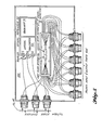
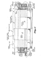
- FIG 4 a 48 terminal data bus comprising four active multiport fiber optic data bus couplers 88 is seen wherein paired transmitter output 115 and signals from other couplers 111 are seen coupled ' between couplers 88.
- a more detailed schematic version showing detailed internal coupler 88 connections is shown in Figure 5 while figure 1 and the aforementioned detailed description in connection therewith may be referred to for a complete understanding of the operation of optical repeater 93, first, and second mixers 89 and 90.
- FIG. 6 A further figure, figure 6, has been included and leading to a further understanding of the present invention since giving in detail legends denoting all incoming and outgoing signals and signal paths intermediate a pair of couplers 88 of a data bus.
- Figures 7, 8, 9, 10 and 11 have been included since exemplary of a method of making active couplers 88 having certain unique features and advantages hereinafter described.
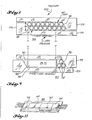
- Figure 7 shows a pair of identically shaped fixtures comprising top fixture 779 and bottom fixture 777 which are utilized to position, retain, and align the several elements of coupler 89 (seen in Figure 10 as including a pair of fiber assemblies 705..and first and second mixer fiber assemblies 707 and 707).
- Top fixture 779 and bottom fixture 777 are generally L shaped with the bottom foot (short leg) 778 of the L having a step height h less than the thickness m (seen in figure 8) of the fiber or mixer array to be confined so that the tightest fit (no extra space between the fibers) is achieved.
- the inner surface 781 of foot 778 is cut in at 30 degrees so that the inner surface or top 781 of foot 778 formst an angle of 120 degrees with respect to the back surface 783 of bottom fixture 777.
- Bottom fixture 777 and top fixture 779 comprise a transparent material, e.g., precision molded plastic or glass drawn from a preform so that subsequent to sandwich assembly of fixtures 777 and 779 about the fiber array (as shown in figure (, viewing can be had during final assembly.
- the dimension t thickness of the long side of L shaped fixture 777) is critical in terms of providing for vertical alignment of mixer and fiber assemblies with respect.to baseplate 931 (as seen in final coupler assembly in figure 10).
- Optical mixer fiber assembly 89 or 90 shown in figure 9 comprises a glass core portion 989 surrounded by a layer of cladding material 981 (of lower index of refraction).
- Fiber assembly 705 is formed as shown in figure 8 by first disposing the two-layer fiber array shown between top and bottom fixtures 779 and 777 and then compressing the two layer fiber array by pressure against fixtures 777 and 779 in an inward direction towards the plane of the fiber array with subsequent second step inward pressure then applied (as represented by arrows 333) in a direction perpendicular to inner surface 781 of feet 778 and 779 with the subsequent curing of the two layer epoxy potted array for permanent retention thereof. Grinding and polishing of the end faces of the two layer fiber array completes the method of making fiber assemblies 705 later utilized in the final composite coupler assembly of figure 10.
- Mixer 89, 90 assembly is shown in figure 9 similarly utilizing the aforementioned method and top and bottom L-shaped fixtures 779 and 777.
- Final assembly of active coupler 88 is shown (top view) in figure 10 and (in perspective) in figure 11. As observed, two mixer fiber assemblies 89 and 90 and two fiber assemblies 705 are aligned to form the final assembly. Vertical alignment is achieved by assembling two of elements 705 and elements 89 and 90 on common base plate 931. Lateral alignment is achieved by visual observation of the aforementioned elements through transparent positioning fixtures. Elements of the final assembly forming active coupler 88 are permanently secured in an integral structure by an optical grade epoxy (not shown for clarity) to avoid loss and minimize Fresnel reflections at junctions between elements.
Landscapes
- Physics & Mathematics (AREA)
- General Physics & Mathematics (AREA)
- Optics & Photonics (AREA)
- Optical Communication System (AREA)
Priority Applications (1)
| Application Number | Priority Date | Filing Date | Title |
|---|---|---|---|
| DE8080201167T DE3070867D1 (en) | 1980-12-05 | 1980-12-05 | Optical repeater for use in active multiport fiber optic data bus coupler |
Applications Claiming Priority (2)
| Application Number | Priority Date | Filing Date | Title |
|---|---|---|---|
| US06/026,372 US4261641A (en) | 1979-04-02 | 1979-04-02 | Active multiport fiber optic data bus coupler |
| US06/153,815 US4318873A (en) | 1979-04-02 | 1980-05-27 | Method of bonding an array of optical fibers |
Publications (2)
| Publication Number | Publication Date |
|---|---|
| EP0053637A1 true EP0053637A1 (fr) | 1982-06-16 |
| EP0053637B1 EP0053637B1 (fr) | 1985-07-10 |
Family
ID=26701150
Family Applications (1)
| Application Number | Title | Priority Date | Filing Date |
|---|---|---|---|
| EP80201167A Expired EP0053637B1 (fr) | 1979-04-02 | 1980-12-05 | Répéteur optique appliqué dans des coupleurs de bus de données actives à canaux multiples pour fibres optiques |
Country Status (2)
| Country | Link |
|---|---|
| US (2) | US4261641A (fr) |
| EP (1) | EP0053637B1 (fr) |
Cited By (3)
| Publication number | Priority date | Publication date | Assignee | Title |
|---|---|---|---|---|
| EP0108640A3 (fr) * | 1982-11-05 | 1984-11-07 | Nec Corporation | Réseau optique avec architecture de bus, capable de détecter rapidement des collisions à chaque station de communication |
| GB2156093A (en) * | 1984-03-21 | 1985-10-02 | Standard Telephones Cables Ltd | Multiport optical fibre couplers |
| EP1108236A4 (fr) * | 1999-05-24 | 2005-04-13 | Methode Electronics Inc | Systeme d'interconnexion optique multi-terminaison |
Families Citing this family (13)
| Publication number | Priority date | Publication date | Assignee | Title |
|---|---|---|---|---|
| US4413880A (en) * | 1981-01-02 | 1983-11-08 | Bowmar/Ali, Inc. | Adaptable connector for a fiber optic testing device |
| US4728169A (en) * | 1981-04-27 | 1988-03-01 | Raychem Corp. | Methods and apparatus for optical fiber systems |
| EP0080829B1 (fr) * | 1981-11-26 | 1991-01-30 | Kabushiki Kaisha Toshiba | Système optique de communication |
| CH659528A5 (de) * | 1982-03-16 | 1987-01-30 | V Elektrotech I V I Lenina | Einrichtung zur uebertragung und verteilung einer lichtstrahlung. |
| US4691987A (en) * | 1983-07-08 | 1987-09-08 | Itek Graphix Corp. | Optical fiber cable producer and method of bonding optical fibers to light emitting diodes |
| DE3422972C2 (de) * | 1984-06-22 | 1986-12-11 | Quante Fernmeldetechnik GmbH, 5600 Wuppertal | Vorrichtung zum Positionieren und Fixieren von Lichtleitfasern in einer parallelen Anordnung zu einem Lichtleitfaserarray |
| GB8421104D0 (en) * | 1984-08-20 | 1984-09-26 | British Telecomm | Optical fibre terminations |
| US4673246A (en) * | 1984-08-24 | 1987-06-16 | Pacific Bell | Patch unit for fiber optic distribution network |
| US5023942A (en) * | 1987-06-26 | 1991-06-11 | Martin Marietta | Fault tolerant data transmission network |
| US4870637A (en) * | 1987-12-24 | 1989-09-26 | American Telephone And Telegraph Company | Optical backplane |
| GB2268019B (en) * | 1992-06-15 | 1996-01-10 | Marconi Gec Ltd | Optical network |
| US5786002A (en) * | 1996-04-04 | 1998-07-28 | Siecor Corporation | Guide block assembly for aligning bore forming pins during molding of multi-fiber optical connector ferrules |
| FR2851097B1 (fr) * | 2003-02-11 | 2005-04-29 | Cit Alcatel | Unite de branchement integrable dans un systeme sous-marin de telecommunications, un tel systeme sous-marin de telecommunications et procede de reconfiguration d'un tel systeme sous-marin de telecommunications |
Citations (4)
| Publication number | Priority date | Publication date | Assignee | Title |
|---|---|---|---|---|
| US4090067A (en) * | 1976-11-02 | 1978-05-16 | Sperry Rand Corporation | Optical data communication system |
| US4107518A (en) * | 1977-01-26 | 1978-08-15 | Sperry Rand Corporation | Optical repeater |
| GB1534786A (en) * | 1976-06-29 | 1978-12-06 | Standard Telephones Cables Ltd | Data transmission system |
| US4149072A (en) * | 1977-08-05 | 1979-04-10 | Minnesota Mining And Manufacturing Company | System for flat ribbon optical fiber data communications link |
Family Cites Families (9)
| Publication number | Priority date | Publication date | Assignee | Title |
|---|---|---|---|---|
| GB1062835A (en) * | 1965-05-04 | 1967-03-22 | American Optical Corp | Improvements in or relating to glass fiber light-transmitting devices |
| US3626040A (en) * | 1969-10-06 | 1971-12-07 | American Optical Corp | Method of making fused bundles of light-conducting fibers |
| US3883217A (en) * | 1973-07-05 | 1975-05-13 | Corning Glass Works | Optical communication system |
| CH564889A5 (fr) * | 1973-11-28 | 1975-07-31 | Patelhold Patentverwertung | |
| US3936141A (en) * | 1974-11-29 | 1976-02-03 | The United States Of America As Represented By The Secretary Of The Navy | Multiple optical connector |
| CH607500A5 (fr) * | 1976-03-18 | 1978-12-29 | Patelhold Patentverwertung | |
| CH628152A5 (fr) * | 1977-11-24 | 1982-02-15 | Comp Generale Electricite | Fiche de connecteur fibre a fibre pour cable optique multifibre. |
| JPS54100746A (en) * | 1978-01-25 | 1979-08-08 | Nippon Telegr & Teleph Corp <Ntt> | Multicore connecting end and method for optical fibers |
| DE2811137C2 (de) * | 1978-03-15 | 1982-12-09 | Philips Kommunikations Industrie AG, 8500 Nürnberg | Stecker für Lichtleitfasern mit V-Nut-Führung |
-
1979
- 1979-04-02 US US06/026,372 patent/US4261641A/en not_active Expired - Lifetime
-
1980
- 1980-05-27 US US06/153,815 patent/US4318873A/en not_active Expired - Lifetime
- 1980-12-05 EP EP80201167A patent/EP0053637B1/fr not_active Expired
Patent Citations (4)
| Publication number | Priority date | Publication date | Assignee | Title |
|---|---|---|---|---|
| GB1534786A (en) * | 1976-06-29 | 1978-12-06 | Standard Telephones Cables Ltd | Data transmission system |
| US4090067A (en) * | 1976-11-02 | 1978-05-16 | Sperry Rand Corporation | Optical data communication system |
| US4107518A (en) * | 1977-01-26 | 1978-08-15 | Sperry Rand Corporation | Optical repeater |
| US4149072A (en) * | 1977-08-05 | 1979-04-10 | Minnesota Mining And Manufacturing Company | System for flat ribbon optical fiber data communications link |
Non-Patent Citations (2)
| Title |
|---|
| elektronik, heft 26, 1979, franzis- verlag, münchen t.a. eppes et al.:"aufbau fiberoptischer zwischenverstärker mit niedriger leistungsaufnahme" pages 60-62 page 60, right column, line 1 page 61, right column, line 8 * |
| The Bell System Technical Journal Vol.57, No.6, July-August 1978, American Telephone and Telegraph Company, New York T.L. MAIONE et al. "Practical 45-Mb/S Regenerator for Lightwave Transmission" pages 1837-1856 + fig.2,3,11; page 1840, lines 2-11; page 1846, lines 2-10; page 1853, lines 6-8 + * |
Cited By (3)
| Publication number | Priority date | Publication date | Assignee | Title |
|---|---|---|---|---|
| EP0108640A3 (fr) * | 1982-11-05 | 1984-11-07 | Nec Corporation | Réseau optique avec architecture de bus, capable de détecter rapidement des collisions à chaque station de communication |
| GB2156093A (en) * | 1984-03-21 | 1985-10-02 | Standard Telephones Cables Ltd | Multiport optical fibre couplers |
| EP1108236A4 (fr) * | 1999-05-24 | 2005-04-13 | Methode Electronics Inc | Systeme d'interconnexion optique multi-terminaison |
Also Published As
| Publication number | Publication date |
|---|---|
| EP0053637B1 (fr) | 1985-07-10 |
| US4318873A (en) | 1982-03-09 |
| US4261641A (en) | 1981-04-14 |
Similar Documents
| Publication | Publication Date | Title |
|---|---|---|
| US4257124A (en) | Optical repeater for use in active multiport fiber optic data bus coupler | |
| US4261641A (en) | Active multiport fiber optic data bus coupler | |
| US4149072A (en) | System for flat ribbon optical fiber data communications link | |
| US6661940B2 (en) | Apparatus and method for rebroadcasting signals in an optical backplane bus system | |
| US4573215A (en) | Optical data distribution network with listen-while-talk capabilities | |
| US5228105A (en) | Programmable electro-optic packaging and interconnect system | |
| US4317614A (en) | Fiber optic bus manifold | |
| US5283851A (en) | Optical interconnection strip | |
| US4826275A (en) | Optical communication systems using star couplers | |
| GB2178919A (en) | Fibre-optic distribution system for broadband signals | |
| CA2477757A1 (fr) | Appareil et procedes d'utilisation de reseaux de fibres optiques dans des systemes de communication optique | |
| US5253094A (en) | Optical interconnection network | |
| US5229875A (en) | Fault-tolerant fiber optic coupler/repeater for use in high speed data transmission and the like | |
| JPS5965809A (ja) | 電光送信器及び/又は光電受信器を光導波体に波長に依存して結合する光結合装置 | |
| US5818618A (en) | High-speed serial simplex broadcast data distribution using optics | |
| US5313536A (en) | Modular photonic waveguide distribution system | |
| US4691386A (en) | Optical transmission channel with electrical connectors | |
| US4775210A (en) | Voice and data distribution system with fiber optic multinode star network | |
| US11303379B1 (en) | Communication between data centers using a multi-core fiber | |
| US5201018A (en) | Optical connector with waveguides for device to fiber coupling | |
| US8200096B2 (en) | Optical transceiver | |
| EP0042158B1 (fr) | Coupleur optique de transmission et de réception par fibre optique | |
| US20200132933A1 (en) | Polarization diversity optical interface assembly | |
| US5373386A (en) | Transmission/reception circuit in a passive optical telecommunication system | |
| EP0513993A2 (fr) | Transmission de signaux optiques différentielle en espace libre |
Legal Events
| Date | Code | Title | Description |
|---|---|---|---|
| PUAI | Public reference made under article 153(3) epc to a published international application that has entered the european phase |
Free format text: ORIGINAL CODE: 0009012 |
|
| AK | Designated contracting states |
Designated state(s): DE FR GB IT NL SE |
|
| 17P | Request for examination filed |
Effective date: 19821130 |
|
| ITF | It: translation for a ep patent filed | ||
| GRAA | (expected) grant |
Free format text: ORIGINAL CODE: 0009210 |
|
| AK | Designated contracting states |
Designated state(s): DE FR GB IT NL SE |
|
| PG25 | Lapsed in a contracting state [announced via postgrant information from national office to epo] |
Ref country code: SE Effective date: 19850730 |
|
| REF | Corresponds to: |
Ref document number: 3070867 Country of ref document: DE Date of ref document: 19850814 |
|
| ET | Fr: translation filed | ||
| PLBE | No opposition filed within time limit |
Free format text: ORIGINAL CODE: 0009261 |
|
| STAA | Information on the status of an ep patent application or granted ep patent |
Free format text: STATUS: NO OPPOSITION FILED WITHIN TIME LIMIT |
|
| 26N | No opposition filed | ||
| PGFP | Annual fee paid to national office [announced via postgrant information from national office to epo] |
Ref country code: FR Payment date: 19901221 Year of fee payment: 11 |
|
| ITTA | It: last paid annual fee | ||
| PGFP | Annual fee paid to national office [announced via postgrant information from national office to epo] |
Ref country code: NL Payment date: 19901231 Year of fee payment: 11 |
|
| PGFP | Annual fee paid to national office [announced via postgrant information from national office to epo] |
Ref country code: DE Payment date: 19910131 Year of fee payment: 11 |
|
| PGFP | Annual fee paid to national office [announced via postgrant information from national office to epo] |
Ref country code: GB Payment date: 19911202 Year of fee payment: 12 |
|
| PG25 | Lapsed in a contracting state [announced via postgrant information from national office to epo] |
Ref country code: NL Effective date: 19920701 |
|
| NLV4 | Nl: lapsed or anulled due to non-payment of the annual fee | ||
| PG25 | Lapsed in a contracting state [announced via postgrant information from national office to epo] |
Ref country code: FR Effective date: 19920831 |
|
| REG | Reference to a national code |
Ref country code: FR Ref legal event code: ST |
|
| PG25 | Lapsed in a contracting state [announced via postgrant information from national office to epo] |
Ref country code: GB Effective date: 19921205 |
|
| PG25 | Lapsed in a contracting state [announced via postgrant information from national office to epo] |
Ref country code: DE Effective date: 19930501 |
|
| GBPC | Gb: european patent ceased through non-payment of renewal fee |
Effective date: 19921205 |