EP0053680B1 - Dispositif d'évaluation subjective et objective de la réfraction - Google Patents
Dispositif d'évaluation subjective et objective de la réfraction Download PDFInfo
- Publication number
- EP0053680B1 EP0053680B1 EP81108496A EP81108496A EP0053680B1 EP 0053680 B1 EP0053680 B1 EP 0053680B1 EP 81108496 A EP81108496 A EP 81108496A EP 81108496 A EP81108496 A EP 81108496A EP 0053680 B1 EP0053680 B1 EP 0053680B1
- Authority
- EP
- European Patent Office
- Prior art keywords
- eye
- test
- ray path
- mark
- mirror
- Prior art date
- Legal status (The legal status is an assumption and is not a legal conclusion. Google has not performed a legal analysis and makes no representation as to the accuracy of the status listed.)
- Expired
Links
- 238000005259 measurement Methods 0.000 title 1
- 238000012360 testing method Methods 0.000 claims description 60
- 210000001747 pupil Anatomy 0.000 claims description 17
- 210000001525 retina Anatomy 0.000 claims description 11
- 238000006073 displacement reaction Methods 0.000 claims description 9
- 230000000694 effects Effects 0.000 claims description 6
- 208000001491 myopia Diseases 0.000 claims description 2
- 238000003384 imaging method Methods 0.000 claims 1
- 238000007689 inspection Methods 0.000 description 4
- 208000029091 Refraction disease Diseases 0.000 description 3
- 230000004430 ametropia Effects 0.000 description 3
- 230000004438 eyesight Effects 0.000 description 3
- 230000003287 optical effect Effects 0.000 description 3
- 208000014733 refractive error Diseases 0.000 description 3
- 230000003595 spectral effect Effects 0.000 description 2
- 230000004308 accommodation Effects 0.000 description 1
- 201000009310 astigmatism Diseases 0.000 description 1
- 238000005286 illumination Methods 0.000 description 1
- 230000004379 myopia Effects 0.000 description 1
- 230000005855 radiation Effects 0.000 description 1
- 230000004256 retinal image Effects 0.000 description 1
Images
Classifications
-
- A—HUMAN NECESSITIES
- A61—MEDICAL OR VETERINARY SCIENCE; HYGIENE
- A61B—DIAGNOSIS; SURGERY; IDENTIFICATION
- A61B3/00—Apparatus for testing the eyes; Instruments for examining the eyes
- A61B3/02—Subjective types, i.e. testing apparatus requiring the active assistance of the patient
- A61B3/028—Subjective types, i.e. testing apparatus requiring the active assistance of the patient for testing visual acuity; for determination of refraction, e.g. phoropters
- A61B3/036—Subjective types, i.e. testing apparatus requiring the active assistance of the patient for testing visual acuity; for determination of refraction, e.g. phoropters for testing astigmatism
-
- A—HUMAN NECESSITIES
- A61—MEDICAL OR VETERINARY SCIENCE; HYGIENE
- A61B—DIAGNOSIS; SURGERY; IDENTIFICATION
- A61B3/00—Apparatus for testing the eyes; Instruments for examining the eyes
- A61B3/02—Subjective types, i.e. testing apparatus requiring the active assistance of the patient
- A61B3/028—Subjective types, i.e. testing apparatus requiring the active assistance of the patient for testing visual acuity; for determination of refraction, e.g. phoropters
-
- A—HUMAN NECESSITIES
- A61—MEDICAL OR VETERINARY SCIENCE; HYGIENE
- A61B—DIAGNOSIS; SURGERY; IDENTIFICATION
- A61B3/00—Apparatus for testing the eyes; Instruments for examining the eyes
- A61B3/10—Objective types, i.e. instruments for examining the eyes independent of the patients' perceptions or reactions
- A61B3/103—Objective types, i.e. instruments for examining the eyes independent of the patients' perceptions or reactions for determining refraction, e.g. refractometers, skiascopes
Definitions
- the present invention relates to a device for subjective and objective refraction determination.
- a device for subjective and simultaneous objective refraction determination in which two test marks are simultaneously projected onto different screens in different spectral ranges and the subject observes this screen through a phoropter.
- the light reflected from the retina of the eye is reflected out of the illuminating beam path via a partially transparent mirror and imaged into an image plane by means of optics.
- the observer changes the phoropter setting until the retinal image appears sharp in the image plane.
- the patient can monitor the improvement in vision by observing one of the test marks and can thus participate in the optimal setting himself.
- This device has the disadvantage that correction is only possible in discontinuous steps and only monocularly and that the known device myopia occurs due to the phoropter arranged in front of the patient's eye.
- a device for subjective and objective refraction determination is known, which is designed as a so-called clear view device.
- a test mark is imaged on a concave mirror via two separate projection beam paths, which is attached at a predetermined distance from the subject and is viewed by the subject with both eyes.
- Adjustment systems with continuously changeable spherical and astigmatic effects are arranged in both projection beam paths, which are adjusted until the test person sees the test mark sharply.
- the light reflected by the test person's eyes is reflected by a partially transparent mirror in two observation beam paths, which contain the same adjustment systems as the projection beam paths.
- the disadvantage of this device is that the concave mirror has to be relatively large so that the pupil of the test subject's eyes can adjust to the test pattern, and that the whole device is large.
- the necessary size of the device also contributes to the fact that, due to the large distance between the test person's eyes and the concave mirror, the displacement paths of the adjustment systems are large.
- a partially transparent mirror for deflecting the projection beam path into the eye and seen in the direction of light is arranged in front of this mirror and behind the adjustment system, a lens system, the lens facing the eye has a distance from the eye pupil that is a multiple of the focal length of the lens system and that, together with the eye, images the test symbol on the back of the eye, and that a mirror serving to reflect the observation beam path is arranged in the plane of the image of the eye pupil generated by the lens system .
- the subject sees through the partially transparent mirrors arranged in front of his eyes the bright test symbol superimposed on the image of the surroundings.
- the device itself must not be visible to the patient, i.e. the projection beam paths should expediently run to the side of the test person's eyes. This necessitates a reflection via additional mirrors and thus a relatively large focal length of the lens system used to image the test mark.
- this system is designed as a TeleSystem, the focal length of which is a multiple of the system focal length.
- the relatively small device exit pupils in front of the test person's eyes require the device to be precisely aligned with the eye pupil.
- test mark projector it is advantageous to design the test mark projector in such a way that it displays the test mark after infinity. This allows a split in the parallel beam path coming from the projector tion in two spatially separate projection beam paths that can be shifted relative to one another and relative to the projector for the purpose of adjustment and required settings.
- test mark projector or the test mark or the setting systems can be displaced axially so that the test symbol appears to the test person at a distance of, for example, 400 mm, which corresponds to the close-up distance.
- the mirrors arranged in front of the subject's eyes can be pivoted about the eye pivot point in the device according to the invention.
- the eye position required for close-up inspection is achieved. It is advantageous to couple the mirrors and the elements for shifting the test characters in terms of movement in order to make the operation of the device as simple as possible.
- adjustment systems for the continuous adjustment of spherical and astigmatic effects are arranged in both projection and observation beam paths.
- These adjustment systems are very simple and each consist of a spherical and a Stokes lens, which are axially displaceable together.
- the setting systems in a projection path and the associated observation beam path are each coupled in terms of movement.
- the two observation beam paths are each designed such that the radiation reflected by the eyes is imaged in an image plane.
- This image plane is then viewed by the observer via a known observation system, for example a binocular tube.
- a known observation system for example a binocular tube.
- he can sharply image the test mark on the retina of the eyes by moving the adjustment systems in the beam paths.
- the patient observes the test sign in a clear and unobstructed view and can constantly track the objective attitude by the observer and correct it subjectively.
- a subjective determination is expediently made after the objective determination, which the test person can also carry out himself.
- the new device With the new device, an objective and subjective refraction determination can thus be carried out independently of one another for both eyes of the test person, the test person having a clear, unobstructed view.
- the device itself is compact and user-friendly and enables both remote and close inspection.
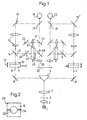
- 1, 1 denotes a light source which illuminates a test mark 3 via a condenser 2.
- a lens system 4 images the test mark 3 to infinity.
- a prism 5 is arranged in the parallel beam path behind the lens system 4 and serves to divide the beam path into two projection beam paths 6 and 7 which are spatially separated from one another, the mirrors 8 and 9 serving to deflect the beam.
- the two projection beam paths 6 and 7 are constructed symmetrically, so that only the beam path 6 is explained below.
- the corresponding elements and functions can also be found in beam path 7.
- the light deflected by the mirror 8 into the projection beam path 6 first passes through an adjustment system which consists of a spherical lens 10 and a Stokes lens 11, which are axially displaceable together, as indicated by the arrow 12.
- the astigmatic effect of the Stokes lens can be changed continuously by means of the operating member 13.
- the resulting spherical component can be compensated for by shifting the setting system 10, 11.
- the test mark 3 is imaged by the lens 10, a lens system 15 and the mirrors 16, 17 onto the retina of the eye 18 to be examined. If this eye has normal vision, the test 3 is imaged by the lens 10 into the focal point of the lens system 15 on the projector side. The eye 18 then images the test mark 3 imaged by the system 15 towards infinity sharply on the retina, i.e. the test subject sees the test mark sharply.
- the mirror 17 arranged in front of the eye 18 is partially transparent, so that the test subject can look at the surroundings in a completely relaxed manner, overlaying the bright test image.
- the lens 10 is shifted axially until the test mark 3 is sharply imaged on the retina of the eye.
- the axial position of the lens 10 is a measure of the spherical refraction.
- Astigmatic ametropia is corrected by operating the Stokes lens 11. It will, as shown, together with the lens 10 axially shifted, since a change in distance between the lenses 10 and 11 would lead to a distortion of the astigmatic correction.
- the position of the operating member 13 is a measure of the astigmatic refraction value sought.
- the two projection beam paths 6 and 7 run laterally from the eyes 18 and 20 in order to avoid device mopia. This requires a large distance between the mirrors 16 and 17.
- the lens system 15 is designed as a telesystem.
- the distance of the lens facing the eye from the pupil of the eye 18 thus becomes a multiple of the focal length of the system 15.
- a displacement path of the setting system 10, 11 of 1 mm corresponds approximately to a change in the refraction value by one diopter.
- the light reflected by the retina of the eye 18 is reflected into the observation beam path 21 via a mirror 14 arranged in the projection beam path 6.
- This mirror is arranged in such a way that the lens system 15 images the pupil of the eye 18 in its plane.
- the mirror 14 has a central, partially transparent area 22 which is surrounded by a reflecting area 23. This area 23 bears a mark 24.
- the projection beam path 6 runs through the central area 23. An exact adjustment of the overall device is achieved when the observer sees the eye pupil in the central area 23 and the mark 24 lies symmetrically to it.
- the mirror 14 can be folded out. This enables the exit pupil of the projection beam path to be enlarged in the case of a subjective eye examination.
- the observation beam path 21 contains an adjustment system 25, 26 which is constructed in the same way as the adjustment system 10, 11 in the projection beam path 6 and which, as arrow 27 shows, is axially displaceable.
- the displacement of the adjustment systems 10, 11 and 25, 26 is coupled.
- the retina of the eye 18 is imaged to infinity by the adjustment system 25, 26.
- a lens system 29 After deflection on the foldable mirror 28, a lens system 29 generates a real image of the retina in the image plane 30.
- a lens 31 is arranged parallel to the setting system 25, 26.
- the light coming from the mirror 14 can be guided over the mirrors 33, 34 and the lens 31 by means of a foldable mirror 32.
- An image of the pupil of the eye 18 is generated in the image plane 30.
- the image plane 30 is observed by means of an observation system, not shown here, for example a binocular tube.
- the image generated in plane 30 is made visible using an image converter.
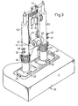
- the device shown in its optical structure in FIG. 1 can be accommodated in a housing, as shown in FIG. 3.
- the elements 2 to 5 are arranged in the base 51, while the tubes 52 and 53 receive the projection beam paths 6 and 7.
- the elements 8 and 10 to 16 are arranged in the tube 52; the partially transparent mirrors 17, 19 are carried by the tubes 52, 53.
- 54 is a headrest for the test subject, which is adjustable in height by means of the rings 35.
- Two rings 36, 37 on the tubes 52, 53 are used to adjust the height of the device.
- the actuating members 38, 40 serve for the axial displacement of the setting systems 10, 11 and the setting systems coupled therewith in the observation beam path 21.
- the members 39, 41 serve for setting the astigmatism.
- the observation beam paths are accommodated in the tube 42, which consists of two parts which can be moved into one another.
- a slide 43 is displaceably arranged on the tube 42 and can optionally be brought into the positions which enable the test mark images generated in the image plane 30 to be viewed.
- the test mark image generated by the right eye 18 is e.g. observed through the opening 44 in the tube 42.
- the correct determination of the refractive condition depends on the corneal vertex distance.
- the device is calibrated to a corneal vertex distance of 16 mm.
- the lens 31 focuses on the location of the mirror 14 or on the mark 24.
- the device is shifted in the direction of the arrows 46 until the pupil of the eye appears simultaneously with the mark 24 in the image plane 30.
- the corneal vertex distance is set correctly.
- a marking (not shown here) which is arranged symmetrically with respect to the pupil of the device and which enables the device to be adjusted to the subject's eyes from the side and height.
- the next step is the objective refraction.
- the setting elements 10, 11 and coupled with them the setting elements 25, 26 are shifted until the test mark 3 appears sharp in the image plane via the actuators 38, 39.
- the observation takes place through the opening 44.
- the test person can observe this setting himself in a controlling manner if light in the visible spectral region is used to project the test mark 3.
- the subject himself or the observer can bring about an optimal correction of the ametropia by actuating the members 38, 39, 40, 41.
- the subject adjusts the device until he sees test mark 3 with both eyes optimally. This adjustment can be made under constant control by observing the image plane 30.
- the device shown also enables a close inspection.
- the projector 1 to 4 is axially shifted until the test mark 3 appears in the plane of the close-up distance (e.g. 400 mm).
- the mirrors 17, 19 are pivoted about the point of rotation of the eye, specifically by the angle by which the eye rotates when looking from a distance into the vicinity.
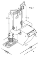
- FIG. 4 shows an embodiment in which, instead of the observation device 43 of FIG. 3, a projection attachment 47 is used which is fixedly connected to the base 51 and projects the test marks 3a, 3b onto a screen.
- a projection attachment 47 is used which is fixedly connected to the base 51 and projects the test marks 3a, 3b onto a screen.
- Such a device is advantageously used when 3 infrared light is used to project the test mark.
Landscapes
- Life Sciences & Earth Sciences (AREA)
- Health & Medical Sciences (AREA)
- Medical Informatics (AREA)
- Biophysics (AREA)
- Ophthalmology & Optometry (AREA)
- Engineering & Computer Science (AREA)
- Biomedical Technology (AREA)
- Heart & Thoracic Surgery (AREA)
- Physics & Mathematics (AREA)
- Molecular Biology (AREA)
- Surgery (AREA)
- Animal Behavior & Ethology (AREA)
- General Health & Medical Sciences (AREA)
- Public Health (AREA)
- Veterinary Medicine (AREA)
- Eye Examination Apparatus (AREA)
Claims (10)
Applications Claiming Priority (2)
| Application Number | Priority Date | Filing Date | Title |
|---|---|---|---|
| DE19803045139 DE3045139A1 (de) | 1980-11-29 | 1980-11-29 | Vorrichtung zur subjektiven und objektiven refraktionsbestimmung |
| DE3045139 | 1980-11-29 |
Publications (2)
| Publication Number | Publication Date |
|---|---|
| EP0053680A1 EP0053680A1 (fr) | 1982-06-16 |
| EP0053680B1 true EP0053680B1 (fr) | 1984-03-07 |
Family
ID=6117962
Family Applications (1)
| Application Number | Title | Priority Date | Filing Date |
|---|---|---|---|
| EP81108496A Expired EP0053680B1 (fr) | 1980-11-29 | 1981-10-19 | Dispositif d'évaluation subjective et objective de la réfraction |
Country Status (4)
| Country | Link |
|---|---|
| US (1) | US4465348A (fr) |
| EP (1) | EP0053680B1 (fr) |
| JP (1) | JPS57117828A (fr) |
| DE (2) | DE3045139A1 (fr) |
Families Citing this family (39)
| Publication number | Priority date | Publication date | Assignee | Title |
|---|---|---|---|---|
| JPS5944237A (ja) * | 1982-09-03 | 1984-03-12 | 株式会社ニコン | 自覚式検眼装置 |
| JPS5980227A (ja) * | 1982-10-29 | 1984-05-09 | 株式会社ニデツク | 眼屈折力測定装置 |
| JPS5985643A (ja) * | 1982-11-06 | 1984-05-17 | 株式会社トプコン | 遠用および近用屈折度測定装置 |
| JPS5985642A (ja) * | 1982-11-06 | 1984-05-17 | 株式会社トプコン | 自覚式屈折度測定装置 |
| DE3315939A1 (de) * | 1983-05-02 | 1984-11-08 | Oculus-Optikgeräte GmbH, 6330 Wetzlar | Vorrichtung zur augenfraktionsbestimmung |
| JPS6092730A (ja) * | 1983-10-26 | 1985-05-24 | 株式会社トプコン | 眼位検査装置 |
| JPS60210237A (ja) * | 1984-04-05 | 1985-10-22 | 株式会社トプコン | 近用屈折力測定装置 |
| JPS60222028A (ja) * | 1984-04-19 | 1985-11-06 | 株式会社トプコン | 眼屈折検査装置 |
| DD226187A1 (de) * | 1984-08-01 | 1985-08-21 | Zeiss Jena Veb Carl | Vorrichtung zur pruefung der sehschaerfe und des binokularsehens |
| JPS6399835A (ja) * | 1987-05-29 | 1988-05-02 | 株式会社 ニデック | 自覚式眼屈折力測定装置 |
| JPS63119738A (ja) * | 1987-10-07 | 1988-05-24 | 株式会社ニデック | 他覚的眼屈折力測定装置 |
| DD273771B5 (de) * | 1988-07-11 | 1997-01-23 | Carn Zeiss Jena Gmbh | Verfahren und Anordnung zur Nahbrillenbestimmung |
| US6522939B1 (en) * | 1996-07-01 | 2003-02-18 | Robert D. Strauch | Computer system for quality control correlation |
| UA67870C2 (uk) | 2002-10-04 | 2004-07-15 | Сергій Васильович Молебний | Спосіб вимірювання хвильових аберацій ока |
| US7303281B2 (en) * | 1998-10-07 | 2007-12-04 | Tracey Technologies, Llc | Method and device for determining refractive components and visual function of the eye for vision correction |
| IL137635A0 (en) * | 2000-08-01 | 2001-10-31 | Visionix Ltd | Apparatus for interactive optometry |
| AU2002307381A1 (en) * | 2001-04-16 | 2002-10-28 | Tracey Technologies, Llc | Determining clinical refraction of eye |
| EP1444945B1 (fr) * | 2001-11-13 | 2017-03-22 | Kabushiki Kaisha TOPCON | Dispositif d'optometrie |
| KR100679147B1 (ko) * | 2001-11-15 | 2007-02-27 | 가부시키가이샤 탑콘 | 검안장치 및 검안차트 |
| GB2376634B (en) * | 2002-07-13 | 2003-12-10 | Litechnica Ltd | Laser accessory for a binocular indirect ophthalmoscope and binocular indirect ophthalmoscope |
| JP4949376B2 (ja) | 2005-03-21 | 2012-06-06 | ライテンズ オートモーティブ パートナーシップ | 磨耗補償付きベルトテンショナー |
| US7726811B2 (en) | 2006-02-14 | 2010-06-01 | Lai Shui T | Subjective wavefront refraction using continuously adjustable wave plates of Zernike function |
| US7699471B2 (en) * | 2006-02-14 | 2010-04-20 | Lai Shui T | Subjective refraction method and device for correcting low and higher order aberrations |
| WO2008014330A2 (fr) * | 2006-07-25 | 2008-01-31 | Lai Shui T | Procédé permettant de fabriquer une optique de haute précision dotée d'un profil de front d'onde |
| CA2678506C (fr) * | 2007-02-23 | 2016-10-18 | Mimo Ag | Appareil ophtalmologique pour imagerie d'un oeil par tomographie a coherence optique |
| ES2673575T3 (es) | 2007-09-06 | 2018-06-22 | Alcon Lensx, Inc. | Fijación de objetivo precisa de foto-disrupción quirúrgica |
| US9492322B2 (en) * | 2009-11-16 | 2016-11-15 | Alcon Lensx, Inc. | Imaging surgical target tissue by nonlinear scanning |
| US8265364B2 (en) | 2010-02-05 | 2012-09-11 | Alcon Lensx, Inc. | Gradient search integrated with local imaging in laser surgical systems |
| US8414564B2 (en) | 2010-02-18 | 2013-04-09 | Alcon Lensx, Inc. | Optical coherence tomographic system for ophthalmic surgery |
| US8398236B2 (en) * | 2010-06-14 | 2013-03-19 | Alcon Lensx, Inc. | Image-guided docking for ophthalmic surgical systems |
| US9532708B2 (en) | 2010-09-17 | 2017-01-03 | Alcon Lensx, Inc. | Electronically controlled fixation light for ophthalmic imaging systems |
| US8459794B2 (en) | 2011-05-02 | 2013-06-11 | Alcon Lensx, Inc. | Image-processor-controlled misalignment-reduction for ophthalmic systems |
| US9622913B2 (en) | 2011-05-18 | 2017-04-18 | Alcon Lensx, Inc. | Imaging-controlled laser surgical system |
| US8398238B1 (en) | 2011-08-26 | 2013-03-19 | Alcon Lensx, Inc. | Imaging-based guidance system for ophthalmic docking using a location-orientation analysis |
| US9066784B2 (en) | 2011-12-19 | 2015-06-30 | Alcon Lensx, Inc. | Intra-surgical optical coherence tomographic imaging of cataract procedures |
| US9023016B2 (en) | 2011-12-19 | 2015-05-05 | Alcon Lensx, Inc. | Image processor for intra-surgical optical coherence tomographic imaging of laser cataract procedures |
| JP6537843B2 (ja) * | 2014-05-28 | 2019-07-03 | 株式会社トプコン | 検眼装置、検眼用チャートを用いた自覚測定方法 |
| CN106963335B (zh) | 2015-11-13 | 2022-01-04 | 尼德克株式会社 | 主观式检眼装置 |
| EP3355102B1 (fr) | 2017-01-27 | 2025-11-26 | Carl Zeiss Vision International GmbH | Procédé mis en uvre par ordinateur destiné à déterminer des paramètres de centrage |
Family Cites Families (5)
| Publication number | Priority date | Publication date | Assignee | Title |
|---|---|---|---|---|
| US2798408A (en) * | 1953-03-09 | 1957-07-09 | American Optical Corp | Vision testing devices |
| US3524702A (en) * | 1968-09-06 | 1970-08-18 | John G Bellows | Apparatus for objectively and automatically refracting the eye |
| US3874774A (en) * | 1973-06-20 | 1975-04-01 | Humphrey Research Associates I | Eye test apparatus |
| US3927933A (en) * | 1973-08-06 | 1975-12-23 | Humphrey Instruments Inc | Apparatus for opthalmological prescription readout |
| US4105302A (en) * | 1976-06-23 | 1978-08-08 | Tate Jr George W | Automatic refraction apparatus and method |
-
1980
- 1980-11-29 DE DE19803045139 patent/DE3045139A1/de not_active Withdrawn
-
1981
- 1981-10-19 DE DE8181108496T patent/DE3162527D1/de not_active Expired
- 1981-10-19 EP EP81108496A patent/EP0053680B1/fr not_active Expired
- 1981-11-24 US US06/324,403 patent/US4465348A/en not_active Expired - Fee Related
- 1981-11-30 JP JP56190975A patent/JPS57117828A/ja active Pending
Also Published As
| Publication number | Publication date |
|---|---|
| DE3045139A1 (de) | 1982-07-01 |
| JPS57117828A (en) | 1982-07-22 |
| EP0053680A1 (fr) | 1982-06-16 |
| DE3162527D1 (en) | 1984-04-12 |
| US4465348A (en) | 1984-08-14 |
Similar Documents
| Publication | Publication Date | Title |
|---|---|---|
| EP0053680B1 (fr) | Dispositif d'évaluation subjective et objective de la réfraction | |
| DE2843287C2 (fr) | ||
| EP1389943B1 (fr) | Ophtalmoscope | |
| DE68911975T2 (de) | Ophthalmoskopisches Diagnoseverfahren und Gerät. | |
| DE202005021287U1 (de) | Aberrometer mit Visusbestimmungssystem | |
| EP0363610B1 (fr) | Dispositif d'examen de fonctions visuelles d'un oeil humain | |
| EP0492044B1 (fr) | Appareil destiné à l'essai de la fonction visuelle | |
| DE102005032501A1 (de) | Vorrichtung zur Untersuchung vorderer und hinterer Augenabschnitte | |
| WO1993014691A1 (fr) | Dispositif de refraction pour la determination subjective des proprietes visuelles spheriques et astigmatiques de l'×il | |
| EP0029203A1 (fr) | Instrument ophtalmologique pour l'examen de segments antérieurs et postérieurs de l'oeil | |
| EP0608516B1 (fr) | Ophtalmoscope | |
| DE19501415C2 (de) | Sehtestgerät | |
| EP0004566B1 (fr) | Dispositif pour la projection d'optotypes | |
| DE19502337C2 (de) | Vorrichtung und Verfahren zur Prüfung von Sehfunktionen | |
| DE19540802A1 (de) | Vorrichtung und Verfahren zur Prüfung von Sehfunktionen | |
| DE3437234C2 (de) | Vorrichtung zur Bestimmung der potentiellen Sehschärfe unter Verwendung eines Spaltlampenmikroskops | |
| EP0038525B1 (fr) | Dispositif pour déterminer l'état de réfraction oculaire | |
| DE4422071B4 (de) | Netzhaut-Blutströmungsgeschwindigkeits-Meßeinrichtung | |
| CH646322A5 (de) | Geraet zur subjektiven refraktionsbestimmung. | |
| DD269781A1 (de) | Anordnung zur messung am augenhintergrund | |
| DE2940519C2 (de) | Gerät zur subjektiven Refraktionsbestimmung | |
| DE3818331C2 (de) | Anordnung und Verfahren zur hochauflösenden Ophthalmoskopie | |
| DE610076C (de) | Augenspiegel | |
| EP4387503A1 (fr) | Dispositif et procédé pour orienter un oeil | |
| DE4006324A1 (de) | Anordnung und verfahren zur fehlerfreien bestimmung der fehlsichtigkeit von patienten |
Legal Events
| Date | Code | Title | Description |
|---|---|---|---|
| PUAI | Public reference made under article 153(3) epc to a published international application that has entered the european phase |
Free format text: ORIGINAL CODE: 0009012 |
|
| AK | Designated contracting states |
Designated state(s): CH DE FR GB |
|
| 17P | Request for examination filed |
Effective date: 19820422 |
|
| GRAA | (expected) grant |
Free format text: ORIGINAL CODE: 0009210 |
|
| AK | Designated contracting states |
Designated state(s): CH DE FR GB LI |
|
| REF | Corresponds to: |
Ref document number: 3162527 Country of ref document: DE Date of ref document: 19840412 |
|
| ET | Fr: translation filed | ||
| PGFP | Annual fee paid to national office [announced via postgrant information from national office to epo] |
Ref country code: DE Payment date: 19841027 Year of fee payment: 4 |
|
| PGFP | Annual fee paid to national office [announced via postgrant information from national office to epo] |
Ref country code: FR Payment date: 19841031 Year of fee payment: 4 |
|
| PGFP | Annual fee paid to national office [announced via postgrant information from national office to epo] |
Ref country code: CH Payment date: 19841109 Year of fee payment: 4 |
|
| PLBE | No opposition filed within time limit |
Free format text: ORIGINAL CODE: 0009261 |
|
| STAA | Information on the status of an ep patent application or granted ep patent |
Free format text: STATUS: NO OPPOSITION FILED WITHIN TIME LIMIT |
|
| 26N | No opposition filed | ||
| PG25 | Lapsed in a contracting state [announced via postgrant information from national office to epo] |
Ref country code: LI Effective date: 19861031 Ref country code: CH Effective date: 19861031 |
|
| PG25 | Lapsed in a contracting state [announced via postgrant information from national office to epo] |
Ref country code: FR Free format text: LAPSE BECAUSE OF NON-PAYMENT OF DUE FEES Effective date: 19870630 |
|
| REG | Reference to a national code |
Ref country code: CH Ref legal event code: PL |
|
| GBPC | Gb: european patent ceased through non-payment of renewal fee | ||
| PG25 | Lapsed in a contracting state [announced via postgrant information from national office to epo] |
Ref country code: DE Effective date: 19870701 |
|
| REG | Reference to a national code |
Ref country code: FR Ref legal event code: ST |
|
| PG25 | Lapsed in a contracting state [announced via postgrant information from national office to epo] |
Ref country code: GB Effective date: 19881118 |