EP0053715A1 - Verpackungsbehälter mit Auskleidung - Google Patents
Verpackungsbehälter mit Auskleidung Download PDFInfo
- Publication number
- EP0053715A1 EP0053715A1 EP81109206A EP81109206A EP0053715A1 EP 0053715 A1 EP0053715 A1 EP 0053715A1 EP 81109206 A EP81109206 A EP 81109206A EP 81109206 A EP81109206 A EP 81109206A EP 0053715 A1 EP0053715 A1 EP 0053715A1
- Authority
- EP
- European Patent Office
- Prior art keywords
- lining
- preform
- casing
- adapter cover
- fixing
- Prior art date
- Legal status (The legal status is an assumption and is not a legal conclusion. Google has not performed a legal analysis and makes no representation as to the accuracy of the status listed.)
- Granted
Links
- 238000004806 packaging method and process Methods 0.000 title claims abstract description 17
- 238000000034 method Methods 0.000 claims abstract description 18
- 238000004519 manufacturing process Methods 0.000 claims abstract description 12
- 238000007789 sealing Methods 0.000 claims abstract description 4
- 230000000087 stabilizing effect Effects 0.000 claims abstract description 4
- 238000003780 insertion Methods 0.000 claims description 8
- 230000037431 insertion Effects 0.000 claims description 8
- 210000002105 tongue Anatomy 0.000 claims description 6
- 238000000071 blow moulding Methods 0.000 claims description 4
- 239000011111 cardboard Substances 0.000 claims description 4
- 239000002184 metal Substances 0.000 claims description 3
- 239000000123 paper Substances 0.000 claims description 2
- 238000004026 adhesive bonding Methods 0.000 description 2
- 238000013461 design Methods 0.000 description 2
- 238000012545 processing Methods 0.000 description 2
- 239000000047 product Substances 0.000 description 2
- 239000008186 active pharmaceutical agent Substances 0.000 description 1
- 239000007795 chemical reaction product Substances 0.000 description 1
- 230000002349 favourable effect Effects 0.000 description 1
- 239000007788 liquid Substances 0.000 description 1
- 239000005022 packaging material Substances 0.000 description 1
- 230000002093 peripheral effect Effects 0.000 description 1
- 239000002994 raw material Substances 0.000 description 1
- 239000000126 substance Substances 0.000 description 1
- 238000012360 testing method Methods 0.000 description 1
- 238000009423 ventilation Methods 0.000 description 1
- 238000004804 winding Methods 0.000 description 1
Images



Classifications
-
- B—PERFORMING OPERATIONS; TRANSPORTING
- B65—CONVEYING; PACKING; STORING; HANDLING THIN OR FILAMENTARY MATERIAL
- B65D—CONTAINERS FOR STORAGE OR TRANSPORT OF ARTICLES OR MATERIALS, e.g. BAGS, BARRELS, BOTTLES, BOXES, CANS, CARTONS, CRATES, DRUMS, JARS, TANKS, HOPPERS, FORWARDING CONTAINERS; ACCESSORIES, CLOSURES, OR FITTINGS THEREFOR; PACKAGING ELEMENTS; PACKAGES
- B65D77/00—Packages formed by enclosing articles or materials in preformed containers, e.g. boxes, cartons, sacks or bags
- B65D77/04—Articles or materials enclosed in two or more containers disposed one within another
- B65D77/06—Liquids or semi-liquids or other materials or articles enclosed in flexible containers disposed within rigid containers
- B65D77/062—Flexible containers disposed within polygonal containers formed by folding a carton blank
- B65D77/065—Spouts, pouring necks or discharging tubes fixed to or integral with the flexible container
-
- B—PERFORMING OPERATIONS; TRANSPORTING
- B29—WORKING OF PLASTICS; WORKING OF SUBSTANCES IN A PLASTIC STATE IN GENERAL
- B29C—SHAPING OR JOINING OF PLASTICS; SHAPING OF MATERIAL IN A PLASTIC STATE, NOT OTHERWISE PROVIDED FOR; AFTER-TREATMENT OF THE SHAPED PRODUCTS, e.g. REPAIRING
- B29C2949/00—Indexing scheme relating to blow-moulding
- B29C2949/07—Preforms or parisons characterised by their configuration
- B29C2949/0715—Preforms or parisons characterised by their configuration the preform having one end closed
-
- B—PERFORMING OPERATIONS; TRANSPORTING
- B29—WORKING OF PLASTICS; WORKING OF SUBSTANCES IN A PLASTIC STATE IN GENERAL
- B29C—SHAPING OR JOINING OF PLASTICS; SHAPING OF MATERIAL IN A PLASTIC STATE, NOT OTHERWISE PROVIDED FOR; AFTER-TREATMENT OF THE SHAPED PRODUCTS, e.g. REPAIRING
- B29C49/00—Blow-moulding, i.e. blowing a preform or parison to a desired shape within a mould; Apparatus therefor
- B29C49/02—Combined blow-moulding and manufacture of the preform or the parison
- B29C49/06—Injection blow-moulding
-
- B—PERFORMING OPERATIONS; TRANSPORTING
- B31—MAKING ARTICLES OF PAPER, CARDBOARD OR MATERIAL WORKED IN A MANNER ANALOGOUS TO PAPER; WORKING PAPER, CARDBOARD OR MATERIAL WORKED IN A MANNER ANALOGOUS TO PAPER
- B31B—MAKING CONTAINERS OF PAPER, CARDBOARD OR MATERIAL WORKED IN A MANNER ANALOGOUS TO PAPER
- B31B2105/00—Rigid or semi-rigid containers made by assembling separate sheets, blanks or webs
-
- B—PERFORMING OPERATIONS; TRANSPORTING
- B31—MAKING ARTICLES OF PAPER, CARDBOARD OR MATERIAL WORKED IN A MANNER ANALOGOUS TO PAPER; WORKING PAPER, CARDBOARD OR MATERIAL WORKED IN A MANNER ANALOGOUS TO PAPER
- B31B—MAKING CONTAINERS OF PAPER, CARDBOARD OR MATERIAL WORKED IN A MANNER ANALOGOUS TO PAPER
- B31B2120/00—Construction of rigid or semi-rigid containers
- B31B2120/40—Construction of rigid or semi-rigid containers lined or internally reinforced
- B31B2120/402—Construction of rigid or semi-rigid containers lined or internally reinforced by applying a liner to already made boxes, e.g. opening or distending of the liner or the box
- B31B2120/407—Construction of rigid or semi-rigid containers lined or internally reinforced by applying a liner to already made boxes, e.g. opening or distending of the liner or the box involving forming of the liner before inserting
-
- Y—GENERAL TAGGING OF NEW TECHNOLOGICAL DEVELOPMENTS; GENERAL TAGGING OF CROSS-SECTIONAL TECHNOLOGIES SPANNING OVER SEVERAL SECTIONS OF THE IPC; TECHNICAL SUBJECTS COVERED BY FORMER USPC CROSS-REFERENCE ART COLLECTIONS [XRACs] AND DIGESTS
- Y10—TECHNICAL SUBJECTS COVERED BY FORMER USPC
- Y10S—TECHNICAL SUBJECTS COVERED BY FORMER USPC CROSS-REFERENCE ART COLLECTIONS [XRACs] AND DIGESTS
- Y10S493/00—Manufacturing container or tube from paper; or other manufacturing from a sheet or web
- Y10S493/901—Rigid container
- Y10S493/906—Rigid container having multilayer wall
- Y10S493/907—Lined
Definitions
- the invention relates to a method for producing a packaging container with mechanically stabilizing, made of paper, cardboard, metal or a combination thereof and a sealing insert inserted therein, formed as a plastic bladder with a molded neck part and an outstanding neck part, in which the lining starts from blown into a preform, the casing is produced in a separate process and the lining is inserted into the casing.
- the invention further relates to linings, adapter covers and sleeves for performing the method.
- DE-DS 29 15 228 describes a packaging container which essentially consists of a thin-walled inner bladder which envelops the respective, for example liquid or free-flowing, product with a molded-on mouth or neck part and a shape-stabilizing outer wrapper surrounding the bladder or lining or shell exists.
- the envelope can also be a folding box, for example.
- the packaging container is to be designed or manufactured by quantitative and qualitative coordination of the packaging materials used so that an economically particularly favorable end product is created for certain volume ranges, which, if desired, can be stored in a food-safe, chemical-resistant, highly gas-tight, empty state and to transport, to save raw materials, easy to fold after use, excellent to decorate. ren and / or to be closed in any way. It is difficult to assemble the casing and lining when assembling the packaging.
- the invention has for its object to provide a method for producing a mechanically stabilizing envelope with a separately produced sealing liner packaging container, in which the individual parts of the packaging are to be made on known systems and to integrate the assembly of these individual parts in the production process with little effort is.
- the solution according to the invention consists in that the casing and the lining are coupled to one another with the aid of an adapter cover connected to the casing and adapted to an opening in the casing.
- the adapter lid used according to the invention is a "lid" in the general sense, ie the adapter lid can represent any closure in the head, in the wall or in the bottom of the casing.
- the preform used to connect the plastic bladder or the lining is pushed over the preform before it is formed, in particular inflated, and locked there in a position secured against rotation in the circumferential direction.
- the adapter cover is then secured in the axial direction of the bladder or lining produced from the preform, before or after insertion into the sleeve. This creates a firm, inseparable connection between Adapter cover and lining.
- the adapter lid should advantageously be designed such that a simple connection into the opening of a casing, for example a pre-glued folding box, which has a corresponding design at its opening, can be used to establish a secure connection with the casing, which can only be released by destroying the packaging.
- the invention further relates to a lining - for carrying out the method and is thereby characterized by fixing cams of the preform formed on the neck of the preform and designed with a view to independently threading fixing lugs of the adapter cover to fix the adapter cover relative to the preform in the circumferential direction. Furthermore, the invention relates to locking means on the adapter cover for fixing on the sleeve and molded with regard to threading fixing cams of the lining or the front Shaped fixing cams on the edge of a lid opening for fixing the cover in the circumferential direction. Finally, the invention relates to a cover with means for latching the adapter cover on the edge of the circumference of an opening of the cover serving to insert the lining and to be closed with the cover.
- the invention is described below in part using the example of folding boxes. However, it is analogously applicable to the use of other sleeves, e.g. a winding tube with a flanged edge, a metal vessel with a corresponding head cover design, a drum-like structure and containers of a similar type.
- other sleeves e.g. a winding tube with a flanged edge, a metal vessel with a corresponding head cover design, a drum-like structure and containers of a similar type.
- the preform is produced at 1 and the adapter at 2, the preform is tempered at 3, the adapter cover is fed from 2 at 4 and slipped over the tempered preform from 3; at 5 the preform is formed into a bladder, at 6 the finished bladder is deaerated and at 7 the deaerated bladder or lining pre-assembled with the adapter cover is made available for further processing in the final assembly device.
- the folding box blank is produced at 8, the folding box is tubed at 9, the folding box base is glued at 10, and the folding box is made available at 11 for further processing in the final assembly device.
- the lining with the adapter lid is entered at 12 and in the process put on a mandrel, the length of which corresponds approximately to the elongated length of the lining; the mandrel with liner then swivels up to position 13 in the direction of insertion, where the folding box at 14 is pushed over the liner and mandrel until the adapter cover snaps into place on the folding box.
- the assembled packaging is pulled off the mandrel at 15, the packaging can be fed to the filling device at 16 and the holding mandrel swivels back into the actuating position at 17.
- an adapter cover which is adapted to an opening of the casing is already fixed on the preform for producing the lining before being inflated, the manufacture of the packaging, including the assembly and insertion of the casing and casing, can be integrated into an automatic assembly process.
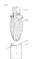
- a preform suitable for carrying out the method according to the invention is shown partially in section in FIG. 2 and is designated overall by 18.
- Exemplary fixing cams 19 which run out in tips 20 are provided on the neck of the preform 18. These cams 19 are used for radial fixing or for fixing the adapter cover 22 (see FIGS. 3 to 5) in the circumferential direction.
- the tips 20 work together hang with the adjoining radii 21 an independent threading of the fixing cams 30 of the adapter cover 22nd
- FIG. 3 Such an adapter cover 22 is shown in section in FIG. 3 in an exemplary embodiment.
- Fig. 4 shows the same adapter cover in a top view and Fig. 5 in a view from below.
- This adapter lid 22 has a downward-facing edge 23 which - depending on the placement on the folding box or depending on the shape of the folding box (see FIGS. 6 to 8) - is to be arranged all the way round, on three sides or only on two opposite sides.
- an insertion bevel 24 is provided on the inside.
- Each edge side is assigned at least one locking cam 25, which has an undercut 26 and an insertion bevel 27.
- a circular or also differently shaped - polygonal, oval - opening 28 surrounded by a collar 29 is provided in the adapter cover 22.
- projecting or raised fixing cams 30 are arranged, which run according to the fixing cams 19 of the preform 18 over radii 21 in tips 20.
- the tips of the preform 18 are directed in exactly the opposite direction to those in the adapter cover 22.
- the adapter cover On the top of the adapter cover there is a peripheral edge 31 which forms a kind of drip tray 32 in the ready-made state. After use and reclosing of the packaging by means of a dosing cap, this prevents the consumer from any product residues from the dosing cap beyond the edge of the adapter can flow on the casing.
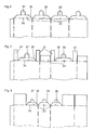
- FIG. 6 shows an example of the upper part of a folding box blank for producing a square folding box
- Fig. 7 the same is shown for a rectangular folding box with a centrally arranged opening
- Fig. 8 for a rectangular folding box with a laterally arranged opening.
- the alternative folding box blanks shown in FIGS. 6 to 8 have at least two profile flaps 33 on the head side, depending on the desired placement of the adapter lid and thus the mouth opening of the lining or bladder on the folding box or depending on the shape of the folding box.
- each profile flap 33 extends conically on both sides over tapering side edges 35 towards the flap end 36.
- the tongue 37 is particularly advantageous for the simple feasibility of the method for assembling lining; Adapter lid and cover or folding box.
- FIGS. 6 to 8 Examples are other folding boxes that can be used to snap an adapter lid into place, e.g. B. by gluing a cardboard strip into the upper area of the folding box blank, behind the lower end of which the locking cams snap in, or by making punched-outs in the blank or cardboard strips into which the locking cams can engage.
- FIG. 9 the assembly of the combination of the liner / adapter cover with the folding box according to FIG. 7 in the position shortly before the liner is immersed in the box is shown schematically;
- Fig. 10 shows in partial section the assembly after immersing the lining shortly before the adapter cover snaps in; and
- FIG. 11 finally shows, in partial section, the packaging which has already been assembled by the method according to the invention.
- Fig. 9 pre-assembled adapter cover and lining as unit 39 on the mandrel 40 and the folding box is glued with Fig. 7 head side flaps 41 with its mouth opening positioned exactly above the center of the mandrel.
- the profile tabs 33 are inclined slightly inwards with angled tongues 37.
- the immersed lining has pressed the profile tabs 33 into the interior of the box.
- the locking cams 25 now immersed in the folding box give way slightly inwards and allow the folding box wall 42 to be threaded with the test flaps 33 folded inwards between the collar 23 and the locking cams 25.
- 11 shows the state of the packaging after the end of the inventive method.
- the folding box wall 42 is clamped with the folded-over profile tabs 33 between the edge 23 and the locking cams 25. The latter have returned to their original position because the undercut could snap behind the profile flap end 36.
Landscapes
- Engineering & Computer Science (AREA)
- Mechanical Engineering (AREA)
- Making Paper Articles (AREA)
- Blow-Moulding Or Thermoforming Of Plastics Or The Like (AREA)
- Packages (AREA)
- Packging For Living Organisms, Food Or Medicinal Products That Are Sensitive To Environmental Conditiond (AREA)
- Cartons (AREA)
- Manufacture Of Macromolecular Shaped Articles (AREA)
- Auxiliary Devices For And Details Of Packaging Control (AREA)
Abstract
Description
- Die Erfindung betrifft ein Verfahren zum Herstellen eines Verpackungsbehälters mit mechanisch stabilisierender, aus Papier, Pappe, Metall oder einer Kombination daraus bestehender Hülle und darin eingesetzter, dichtender, als Kunststöffblase mit angeformtem sowie aus der Hülle hervorragendem Halsteil ausgebildeter Auskleidung, bei dem die Auskleidung ausgehend von einem Vorformling geblasen, in einem getrennten Verfahren die Hülle hergestellt und die Auskleidung in die Hülle eingesetzt wird. Die Erfindung betrifft ferner Auskleidungen, Adapterdeckel und Hüllen zum Durchführen des Verfahrens.
- In der DE-DS 29 15 228 wird ein Verpackungsbehälter beschrieben, der im wesentlichen aus einer dünnwandigen, das jeweilige, z.B. flüssige oder rieselfähige, Produkt umhüllenden inneren Blase mit angeformtem Mündungs- oder Halsteil und einer die Blase bzw. Auskleidung umgebenden, formstabilisierenden äußeren Umhüllung bzw. Hülle besteht. Die Hülle kann beispielsweise auch eine Faltschachtel sein. Der Verpackungsbehälter ist durch quantitative und qualitative Abstimmung der verwendeten Packstoffe untereinander so auszubilden bzw. herzustellen, daß jeweils für bestimmte Volumenbereiche ein wirtschaftlich besonders günstiges Endprodukt entsteht, welches je nach Wunsch lebensmittelecht, chemikalienbeständig, in hohem Maße gasdicht, in leerem Zustand platzsparend zu lagern und zu transportieren, rohstoffsparend herzustellen, nach Gebrauch leicht zusammenzulegen, hervorragend zu dekorie- . ren und/oder auf beliebige Weise zu verschließen ist. Schwierigkeiten bereitet das Zusammensetzen von Hülle und Auskleidung beim Konfektionieren der Verpackung.
- Der Erfindung liegt die Aufgabe zugrunde, ein Verfahren zum Herstellen des eine mechanisch stabilisierende Hülle mit getrennt davon hergestellter dichtender Auskleidung aufweisenden Verpackungsbehälters zu schaffen, bei dem die Einzelteile der Verpackung auf bekannten Anlagen herzustellen sind und das Zusammenfügen dieser Einzelteile in den Produktionsprozess wenig aufwendig zu integrieren ist. Die erfindungsgemäße Lösung besteht darin, daß die Hülle und die Auskleidung mit Hilfe eines mit der Auskleidung verbundenen, einer Öffnung der Hülle angepaßten Adapterdeckels miteinander gekoppelt werden.
- Bei dem erfindungsgemäßen verwendeten Adapterdeckel handelt es sich um einen "Deckel" im allgemeinen Sinne, d.h. der Adapterdeckel kann irgendeinen Verschluß im Kopf, in der Wand oder im Boden der Hülle darstellen. Erfindungsgemäß wird der zum Verbinden von Kunststoffblase bzw. Auskleidung bereits vor dem Umformen, insbesondere Aufblasen, des zum Herstellen der Auskleidung verwendeten Vorformlings über den Vorformling geschoben und dort in einer gegen Verdrehung in Umfangsrichtung gesicherten Position arretiert. Durch Umformen des Vorformlings im Streckblasverfahren erfolgt dann - vor oder nach dem Einschieben in die Hülle - auch ein Sichern des Adapterdeckels in axialer Richtung der aus dem Vorformling hergestellten Blase bzw. Auskleidung. Auf diese Weise entsteht eine feste, unlösbare Verbindung zwischen Adapterdeckel und Auskleidung. Der Adapterdeckel soll vorteilhaft so ausgebildet sein, daß durch einfaches Einschieben in die Öffnung einer Hülle, beispielsweise einer vorverklebten Faltschachtel, die an ihrer Öffnung eine entsprechende Gestaltung aufweist, mit der Hülle eine sichere, nur durch Zerstören der Verpackung lösbare Verbindung herzustellen ist.
- Für ein relativ einfaches Zusammenfügen von einerseits Auskleidung und Adapterdeckel und andererseits äußerer Hülle ist es im Rahmen des erfindungsgemäßen Verfahrens von besonderer Bedeutung, daß durch Vorkonfektionieren des aus Vorformling bzw. Auskleidung und Adapterdeckel bestehenden einen Bauelements, welches bereits auf der Streckblasmaschine herzustellen ist, für das Fertig-Konfektionieren wesentliche Adapterdeckel-bereits vor dem Strecken und Aufblasen des Vorformlings auf der Auskleidung festgelegt wird. Auf diese Weise entfällt eine sonst nur schwer zu bewältigende Manipulation mit der forminstabilen fertigen Auskleidung einerseits und dem Adapterdeckel oder einem ähnlichen Bauelement andererseits.
- Die Erfindung bezieht sich ferner auf eine Auskleidung - zum Durchführen des Verfahrens und ist dabei gekennzeichnet durch an dem Hals des Vorformlings angeformte, im Hinblick auf ein selbständiges Einfädeln von Fixiernokken des Adapterdeckels ausgebildete Fixiernocken des Vorformlings zum Festlegen des Adapterdeckels relativ zum Vorformling in der Umfangsrichtung. Weiterhin betrifft die Erfindung Arretiermittel am Adapterdeckel zum Festlegen auf der Hülle sowie angeformte im Hinblick auf ein Einfädeln von Fixiernocken der Auskleidung bzw, des Vorformlings ausgebildete Fixiernocken am Rande einer Dekkelöffnung zum Festlegen des Deckels in der Umfangsrichtung. Schließlich betrifft die Erfindung eine Hülle mit Mitteln zum Einrasten des Adapterdeckels am Rande des Umfangs einer zum Einschieben der Auskleidung dienenden und mit dem Deckel zu verschließenden Öffnung der Hülle.
- Anhand der schematischen Darstellung von Ausführungsbeispielen werden weitere Einzelheiten der Erfindung erläutert. Es zeigen:
- Fig. 1 ein Herstellungs- und Konfektionierschema;
- Fig. 2 einen Vorformling teilweise im Schnitt;
- Fig. 3 einen Adapterdeckel im Schnitt, in der Draufbis 5 sicht und in der Ansicht von unten;
- Fig. 6 verschiedene Faltschachteln; und
- bis 8
- Fig. 9 Verfahrensschritte beim Konfektionieren der bis 11 Baueinheit Auskleidung/Adapterdeckel mit einer Faltschachtel.
- Die Erfindung wird im folgenden teilweise anhand des Beispiels von Faltschachteln beschrieben. Sie ist jedoch sinngemäß ohne weiteres übertragbar auf die Verwendung anderer Hüllen, z.B. eines Wickelrohrs mit gebördeltem Rand, eines Metallgefäßes mit entsprechender Kopfdeckelgestaltung, eines trommelähnlichen Gebildes und Gebinden ähnlicher Art.
- In dem beispielhaften Herstellungs- und Konfektionierschema nach Fig. 1 wird erfindungsgemäß bei 1 der Vorformling und bei 2 der Adapter hergestellt, bei 3 wird der Vorformling-temperiert, bei 4 der Adapterdeckel von 2 zugeführt und über den temperierten Vorformling von 3 gestreift; bei 5 wird der Vorformling zur Blase umgeformt, bei 6 die fertige Blase entlüftet und bei 7 die mit dem Adapterdeckel vorkonfektionierte, entlüftete Blase bzw. Auskleidung zur weiteren Verarbeitung in der Endkonfektionseinrichtung zur Verfügung gestellt.
- In einem parallel laufenden Produlctionszweig wird bei 8 der Faltschachtelzuschnitt hergestellt, bei 9 die Faltschachtel geschlaucht, bei 10 der Faltschachtel-Boden verklebt und bei 11 die Faltschachtel zum weiteren Verarbeiten in der Endkonfektioniereinrichtung zur Verfügung gestellt. In letztere wird bei 12 die Auskleidung mit Adapterdeckel eingegeben und dabei auf einen Dorn gesteckt, dessen Länge etwa der gestreckten Länge der Auskleidung entspricht; der Dorn mit Auskleidung schwenkt dann bis zu Position 13 in Einschubrichtung, wo die Faltschachtel bei 14 zentriert über Auskleidung und Dorn geschoben wird, bis der Adapterdeckel an der Faltschachtel einrastet. Schließlich wird die konfektionierte Verpakkung bei 15 vom Dorn abgezogen, die Verpackung kann bei 16 der Abfülleinrichtung zugeführt werden und der Aufnahmedorn schwenkt bei 17 zurück in die Betätigungsposition.12.
- Dadurch, daß erfindungsgemäß ein einer Öffnung der Hülle angepaßter Adapterdeckel bereits vor dem Aufblasen auf den Vorformling zum Herstellen der Auskleidung fixiert wird, läßt sich also das Herstellen der Verpackung einschließlich des Zusammenfügens und Einschiebens von Auskleidung und Hülle in ein automatisches Konfektionsverfahren integrieren.
- Ein zum Durchführen des erfindungsgemäßen Verfahrens geeigneter Vorformling wird in Fig. 2 teilweise im Schnitt dargestellt und insgesamt mit 18 bezeichnet. Am Hals des Vorformlings 18 werden beispielhafte, in Spitzen 20 auslaufende Fixiernocken 19.vorgesehen. Diese Nocken 19 dienen zum radialen Fixieren bzw. zum Fixieren des Adapterdeckel 22 (vergl. Fig. 3 bis 5) in Umfangsrichtung. Die Spitzen 20 bewirken im Zusammenhang mit den daran anschließenden Radien 21 ein selbständiges Einfädeln der Fixiernocken 30 des Adapterdekkels 22.
- Ein solcher Adapterdeckel 22 wird in Fig. 3 in beispielhafter Ausführung im Schnitt dargestellt. Fig. 4 zeigt den gleichen Adapterdeckel in der Draufsicht und Fig. 5 in der Ansicht von unten. Dieser Adapterdeckel 22 besitzt einen nach unten gerichteten Rand 23, der - je nach Plazierung an der Faltschachtel oder in Abhängigkeit von der Faltschachtel-Formgebung (vergl. Fig. 6 bis 8) - umlaufend, dreiseitig oder nur an zwei gegenüberliegenden Seiten verlaufend anzuordnen ist. Am Rand 23 ist auf der Innenseite eine Einführungsschräge 24 vorgesehen. Jeder Randseite ist mindestens ein Arretiernocken 25 zugeordnet, der eine Hinterschneidung 26 sowie eine Einführungsschrägspitze 27 besitzt.
- Erfindungsgemäß wird im Adapterdeckel 22 eine kreisförmige oder auch anders gestaltete - mehreckige, ovale - von einem Bund 29 umgebende Durchbrechung 28 vorgesehen. Am inneren Umfang des Bundes 29 bzw. am äußeren Umfang der Durchbrechung 28 werden vorspringende bzw. erhabene Fixiernocken 30 angeordnet, die entsprechend den Fixiernocken 19 des Vorformlings 18 über Radien 21 in Spitzen 20 auflaufen. Die Spitzen sind beim Vorformling 18 genau gegenläufig zu denen im Adapterdeckel 22 gerichtet.
- Auf der Oberseite des Adapterdeckels befindet sich ein umlaufender Rand 31, der im fertigkonfektionierten Zustand eine Art Tropfenauffangwanne 32 bildet. Diese verhindert nach Anwendung und Wiederverschließen der Verpackung mittels,Dosierkappe durch den Verbraucher, daß eventuell Produktreste aus der Dosierkappe über den Adapterrand hinaus auf die Umhüllung fließen können.
- Fig. 6 zeigt beispielhaft den oberen Teil eines Faltschachtelzuschnitts zum Herstellen einer quadratischen Faltschachtel, während in Fig. 7 dasselbe für eine rechteckige Faltschachtel mit mittig angeordneter Mündungsöffnung sowie in Fig. 8 für eine rechteckige Faltschachtel mit seitlich angeordneter Mündungsöffnung dargestellt wird. Die in Fig. 6 bis 8 dargestellten alternativen Faltschachtelzuschnitte weisen je nach gewünschter Plazierung des Adapterdeckels und damit der Mündungsöffnung der Auskleidung bzw. Blase an der Faltschachtel bzw. in Abhängigkeit von der Faltschachtelformgebung mindestens zwei Profillaschen 33 an der Kopfseite auf. Jede Profillasche 33 verläuft - ausgehend von einer angeröllten Faltlinie 34 - beidseitig über verjüngende Seitenkanten 35 konisch zum Laschendende 36 hin.
- Vorzugsweise soll sich in der Mitte des Laschenendes 36 eine etwa halbkreisförmige Verlängerung bzw. Zunge 37 befinden, die in Richtung der Linie des Laschenendes 36 von der Kartonaußenseite her eine Ritzung 38 enthält, so daß im geschlauchten Zustand die Zungen 37 leicht nach innen gekippt werden können bzw. von selbst nach innen kippen. Bei dieser oder ähnlicher Anordnung und entsprechendem Aufbau sind die Zungen 37 besonders vorteilhaft für die einfache Durchführbarkeit des erfindungsgemäßen Verfahrens zum Konfektionieren von Auskleidung; Adapterdeckel und Hülle bzw. Faltschachtel.
- Anstelle der in den Fig. 6 bis 8 dargestellen Ausführungsbeispielen sind auch andere Faltschachteln einsetzbar, die das Einrasten eines Adapterdeckels ermöglichen, z. B. durch Einkleben eines Kartonstreifens in den oberen Bereich des Faltschachtelzuschnitts, hinter dessen unteres Ende die Arretiernocken einrasten, oder durch Anbringen von Ausstanzungen im Zuschnitt oder Kartonstreifen, in die die Arretiernocken eingreifen können.
- In Fig. 9 wird in Teilschnitt das Konfektionieren der Kombination von Auskleidungs/Adapterdeckel mit der Faltschachtel gemäß Fig. 7 in der Stellung kurz vor dem Eintauchen der Auskleidung in die Schachtel schematisch dargestellt; Fig. 10 zeigt dann im Teilschnitt das Konfektionieren nach dem Eintauchen der Auskleidung kurz vor dem Einschnappen des Adapterdeckels; und Fig. 11 zeigt schließlich im Teilschnitt die fertig nach dem erfindungsgemäßen Verfahren konfektionierte Verpackung.
- In Fig. 9 stecken vorkonfektioniert Adapterdeckel und Auskleidung als Einheit 39 auf dem Aufnahmedorn 40 und die Faltschachtel ist mit gemäß Fig. 7 verklebten Kopfseitenlaschen 41 mit ihrer Mündungsöffnung exakt über der Mitte des Aufnahmedorns positioniert. Die Profillaschen 33 stehen leicht nach innen geneigt mit abgewinkelten Zungen 37. Im Zustand nach Fig. 10 hat die eingetauchte Auskleidung die Profillaschen 33 ins Kartoninnere gedrückt. Die jetzt in die Faltschachtel eintauchenden Arretiernocken 25 geben leicht nach innen nach und lassen die Faltschachtelwand 42 mit den nach innen umgelegten Prcfillaschen 33 zwischen den Bund 23 und die Arretiernocken 25 einfädeln. Fig. 11 zeigt schließlich den Zustand der Verpackung nach Abschluß des erfindungsgemäßen Verfahrens. Die Faltschachtelwand 42 ist mit den umgelegten Profillaschen 33 zwischen dem Rand 23 und den Arretiernocken 25 eingeklemmte. Letztere haben sich in ihre ursprüngliche Lage zurückgestellt, weil die Hinterschneidung hinter das Profil-Laschenende 36 einschnappen konnte.
-
- 1 Vorformlingsherstellung
- 2 Adapterherstellung
- 3 Vorformling - Temperierung
- 4 Adapterdeckel -.Zuführung
- 5 Vorformlings - Umformung
- 6 Blasenentlüftung
- 7 Endstation Streckblasmaschine
- 8 Faltschachtel-Zuschnitt-Herstellung
- 9 FS-Schlauchen
- 10 FS-Boden- und Kopfseitenlaschen-Verklebung
- 11 Endstation FS-Herstellung
- 12 Eingabestation Endkonfektionierung
- 13 Dorn-Schwenken
- 14 Vorschub Faltschachtel
- 15 Faltschachtel-Abzug
- 16 Endstation Konfektionieren
- 17 Dorn-Aufrichten
- 18 Vorformling
- 19 Fixiernocken
- 20 Spitzen
- 21 Radien
- 22 Adapter-Deckel
- 23 Rand
- .24 Einführungsschräge
- 25 Arretiernocken
- 26 Hinterschneidung
- 27 Einführungsschrägspitze
- 28 Durchbrechung
- 29 Bund
- 30 Fixiernocken
- 31 Rand
- 32 Tropfenauffangwanne
- 33 Profil-Laschen
- 34 Faltlinie
- 35 Seitenkanten
- 36 Laschenende
- 37 Zunge
- 38 Ritzung
- 39 Einheit
- 40 Aufnahmedorn
- 41 Kopfseitenlaschen
- 42 Faltschachtelwand
Claims (7)
Priority Applications (1)
| Application Number | Priority Date | Filing Date | Title |
|---|---|---|---|
| AT81109206T ATE8765T1 (de) | 1980-12-04 | 1981-10-29 | Verpackungsbehaelter mit auskleidung. |
Applications Claiming Priority (2)
| Application Number | Priority Date | Filing Date | Title |
|---|---|---|---|
| DE3045710 | 1980-12-04 | ||
| DE19803045710 DE3045710A1 (de) | 1980-12-04 | 1980-12-04 | Verfahren zum herstellen eines verpackungsbehaelters und mittel zum durchfuehren des verfahrens |
Publications (2)
| Publication Number | Publication Date |
|---|---|
| EP0053715A1 true EP0053715A1 (de) | 1982-06-16 |
| EP0053715B1 EP0053715B1 (de) | 1984-08-01 |
Family
ID=6118286
Family Applications (1)
| Application Number | Title | Priority Date | Filing Date |
|---|---|---|---|
| EP81109206A Expired EP0053715B1 (de) | 1980-12-04 | 1981-10-29 | Verpackungsbehälter mit Auskleidung |
Country Status (7)
| Country | Link |
|---|---|
| US (2) | US4430068A (de) |
| EP (1) | EP0053715B1 (de) |
| JP (1) | JPS57120429A (de) |
| AT (1) | ATE8765T1 (de) |
| DE (2) | DE3045710A1 (de) |
| ES (2) | ES507680A0 (de) |
| ZA (1) | ZA818452B (de) |
Cited By (8)
| Publication number | Priority date | Publication date | Assignee | Title |
|---|---|---|---|---|
| EP0225677A3 (en) * | 1985-12-13 | 1988-06-22 | The Procter & Gamble Company | Blown bag-in-box composite container and method and apparatus for making the same |
| DE3833663A1 (de) * | 1988-10-04 | 1990-04-05 | Konrad Ensslin | Spender fuer desinfektionsmittel, seifencreme, handcreme, hautpflegemittel und dgl. |
| EP0391817A1 (de) * | 1989-04-05 | 1990-10-10 | Cebal S.A. | Spender mit flexiblem Innensack |
| FR2676958A1 (fr) * | 1991-05-31 | 1992-12-04 | Valois | Procede de fabrication d'un recipient a coque exterieure rigide contenant une poche souple, destine notamment a la pulverisation ou a la distribution de produits fluides ou pateux sans reprise d'air. |
| WO1993014356A1 (en) * | 1992-01-17 | 1993-07-22 | Morris White Pty. Ltd. | Fluid storage tank |
| EP0511215A4 (de) * | 1990-01-16 | 1994-03-23 | Scholle Corporation | |
| US5409559A (en) * | 1992-05-20 | 1995-04-25 | Impact International Pty Ltd. | Making a laminated tubular body |
| US7872454B2 (en) | 2003-08-21 | 2011-01-18 | Marvell World Trade Ltd. | Digital low dropout regulator |
Families Citing this family (32)
| Publication number | Priority date | Publication date | Assignee | Title |
|---|---|---|---|---|
| DE3045710A1 (de) * | 1980-12-04 | 1982-07-08 | Henkel KGaA, 4000 Düsseldorf | Verfahren zum herstellen eines verpackungsbehaelters und mittel zum durchfuehren des verfahrens |
| DE3145368A1 (de) * | 1981-11-14 | 1983-05-26 | Henkel KGaA, 4000 Düsseldorf | Verschluss eines verpackungsbehaelters |
| DE3145357A1 (de) * | 1981-11-14 | 1983-05-26 | Henkel KGaA, 4000 Düsseldorf | "verschluss eines verpackungsbehaelters" |
| DE3240300A1 (de) * | 1982-10-30 | 1984-05-03 | Henkel KGaA, 4000 Düsseldorf | Vorrichtung zum herstellen einer dichtenden auskleidung und verfahren zum betrieb der vorrichtung |
| WO1988008401A1 (en) * | 1987-04-23 | 1988-11-03 | Reardon Michael J | Drum liner |
| US4805799A (en) * | 1988-03-04 | 1989-02-21 | Robbins Edward S Iii | Container with unitary bladder |
| DE3808761A1 (de) * | 1988-03-16 | 1989-09-28 | Wolfgang Pfeil | Verfahren und vorrichtung zum abfuellen und verschliessen von behaeltern |
| US4979628A (en) * | 1988-12-22 | 1990-12-25 | Robbins Edward S Iii | Containers having one or more integral annular bands of increased thickness |
| US4930644A (en) * | 1988-12-22 | 1990-06-05 | Robbins Edward S Iii | Thin film container with removable lid and related process |
| US5111971A (en) * | 1989-05-26 | 1992-05-12 | Robert Winer | Self-pressurized container having a convoluted liner and an elastomeric sleeve |
| DE4006305A1 (de) * | 1990-02-28 | 1991-08-29 | Edelmann Carl Gmbh | Verfahren zum herstellen einer mit einem kunststoffinnenbeutel versehenen kartonverpackung fuer die aufnahme schuettfaehiger gueter |
| US4993579A (en) * | 1990-03-26 | 1991-02-19 | Platte Chemical Co. | Bladder type container for toxic materials |
| US5484077A (en) * | 1991-03-13 | 1996-01-16 | The Procter & Gamble Company | Packaging system including small frame with integral lid, bag and external container |
| US5154308A (en) * | 1991-07-19 | 1992-10-13 | Safety-Kleen Corporation | Detachable cover and drum liner for storage and transport of controlled materials |
| IT226638Z2 (it) * | 1992-05-29 | 1997-07-01 | Luigi Goglio | Contenitore rigido per confezioni flessibili intercambiabili |
| US5277015A (en) * | 1992-06-11 | 1994-01-11 | The Procter & Gamble Company | Method and apparatus for inserting a bag into a bottle |
| WO1994019255A1 (en) * | 1993-02-16 | 1994-09-01 | Anatol Nominees Pty. Ltd. | Container system and bag assembly |
| JP2605131Y2 (ja) * | 1993-08-23 | 2000-06-26 | 株式会社細川洋行 | 柔軟容器の保持器 |
| US5765747A (en) * | 1996-03-15 | 1998-06-16 | Westvaco Corporation | Pour spout fitment for gable top container |
| US6132350A (en) * | 1996-11-01 | 2000-10-17 | K&R Equipment, Inc. | Method and apparatus for automatically lining a container |
| US5735786A (en) * | 1996-11-01 | 1998-04-07 | K & R Equipment, Inc. | Method and apparatus for automatically lining a container |
| US7278545B2 (en) * | 2002-03-05 | 2007-10-09 | Chep Technology Pty Limited | Interchangeable fitment apparatus and system |
| CA2508694A1 (en) * | 2002-11-29 | 2004-06-17 | Interbrew S.A. | Method of installing a beverage bag into a container |
| US20060073288A1 (en) * | 2003-08-22 | 2006-04-06 | Garman Thomas B | Securement of attachments to molded plastic preforms or containers |
| GB0411293D0 (en) * | 2004-05-20 | 2004-06-23 | Interbrew Sa | Folded alcohol beverage bag and method |
| ITBO20070086A1 (it) * | 2007-02-15 | 2008-08-16 | Marchesini Group Spa | Macchina per il confezionamento di articoli in astucci |
| US20090127262A1 (en) * | 2007-11-20 | 2009-05-21 | Joe Hsu | Shipping container having a controllably stretchable liner |
| US9402454B2 (en) | 2010-04-21 | 2016-08-02 | James Landy | Fluid application device |
| JP4648501B1 (ja) * | 2010-09-14 | 2011-03-09 | 武内プレス工業株式会社 | 二重エアゾール容器の製造方法、二重エアゾール容器、および、二重エアゾール容器の製造装置 |
| WO2014066467A1 (en) * | 2012-10-23 | 2014-05-01 | Scholle Corporation | Bag in a box assembly |
| US10414568B2 (en) * | 2017-11-20 | 2019-09-17 | The Procter & Gamble Company | Aerosol dispenser with polygonal crimp ring outer container therefor and preform therefor |
| US10492500B1 (en) * | 2018-08-31 | 2019-12-03 | Samuel Siwak | Dispensing baked good container assembly and method |
Citations (2)
| Publication number | Priority date | Publication date | Assignee | Title |
|---|---|---|---|---|
| AT357929B (de) * | 1978-09-12 | 1980-08-11 | Teich Ag Folienwalzwerk | Behaelter fuer fluessige oder rieselfaehige materialien |
| DE2915228A1 (de) * | 1979-04-14 | 1980-10-23 | Henkel Kgaa | Verpackungsbehaelter fuer fluessige und rieselfaehige produkte und verfahren zum herstellen des behaelters |
Family Cites Families (18)
| Publication number | Priority date | Publication date | Assignee | Title |
|---|---|---|---|---|
| US1991223A (en) | 1931-08-17 | 1935-02-12 | Gen Electric | Packing machine |
| US3169086A (en) | 1959-07-14 | 1965-02-09 | Fmc Corp | Method of making lined receptacles |
| US3119543A (en) * | 1961-08-28 | 1964-01-28 | James H Walker | Neck securement for containers |
| US3169690A (en) * | 1961-10-20 | 1965-02-16 | Scholle Container Corp | Container |
| US3219240A (en) | 1962-12-14 | 1965-11-23 | Weyerhaeuser Co | Shipping and dispensing container for liquids |
| US3226002A (en) * | 1963-04-22 | 1965-12-28 | James W Walker | Flexible container, fitting therefor, and composite package |
| US3206075A (en) * | 1963-07-02 | 1965-09-14 | Scholle Container Corp | Dispensing device |
| US3468224A (en) | 1965-03-18 | 1969-09-23 | Sobrefina Sa | Method of forming a container |
| US3423818A (en) | 1966-03-25 | 1969-01-28 | Continental Can Co | Method of producing collapsible plastic liner and assembling liner to aerosol container |
| ES149014Y (es) * | 1968-05-30 | 1970-05-16 | Una pared frontal. | |
| US3727889A (en) * | 1970-05-21 | 1973-04-17 | Chapman Chem Co | Mixing method and apparatus |
| US3672122A (en) | 1970-07-20 | 1972-06-27 | Int Playtex Corp | Bag holder and expander unit |
| US4000834A (en) * | 1975-12-17 | 1977-01-04 | General Electric Company | Apparatus for heating and dispensing flowable material |
| US4342183A (en) | 1976-11-29 | 1982-08-03 | International Paper Company | Process for making a container for storing food |
| US4379455A (en) | 1980-01-21 | 1983-04-12 | Deaton David W | Medical receptacle with disposable liner assembly |
| US4293079A (en) * | 1980-03-24 | 1981-10-06 | Tlb Plastics Corporation | Hinged closure |
| DE3045710A1 (de) * | 1980-12-04 | 1982-07-08 | Henkel KGaA, 4000 Düsseldorf | Verfahren zum herstellen eines verpackungsbehaelters und mittel zum durchfuehren des verfahrens |
| US4413757A (en) * | 1981-03-09 | 1983-11-08 | Adler Harold A | Dispenser for repelling animals |
-
1980
- 1980-12-04 DE DE19803045710 patent/DE3045710A1/de not_active Withdrawn
-
1981
- 1981-10-29 AT AT81109206T patent/ATE8765T1/de not_active IP Right Cessation
- 1981-10-29 DE DE8181109206T patent/DE3165265D1/de not_active Expired
- 1981-10-29 EP EP81109206A patent/EP0053715B1/de not_active Expired
- 1981-11-30 US US06/326,169 patent/US4430068A/en not_active Expired - Fee Related
- 1981-12-03 ES ES507680A patent/ES507680A0/es active Granted
- 1981-12-03 ES ES1981261840U patent/ES261840Y/es not_active Expired
- 1981-12-04 JP JP56194612A patent/JPS57120429A/ja active Granted
- 1981-12-04 ZA ZA818452A patent/ZA818452B/xx unknown
-
1983
- 1983-09-19 US US06/533,347 patent/US4560085A/en not_active Expired - Fee Related
Patent Citations (2)
| Publication number | Priority date | Publication date | Assignee | Title |
|---|---|---|---|---|
| AT357929B (de) * | 1978-09-12 | 1980-08-11 | Teich Ag Folienwalzwerk | Behaelter fuer fluessige oder rieselfaehige materialien |
| DE2915228A1 (de) * | 1979-04-14 | 1980-10-23 | Henkel Kgaa | Verpackungsbehaelter fuer fluessige und rieselfaehige produkte und verfahren zum herstellen des behaelters |
Cited By (10)
| Publication number | Priority date | Publication date | Assignee | Title |
|---|---|---|---|---|
| EP0225677A3 (en) * | 1985-12-13 | 1988-06-22 | The Procter & Gamble Company | Blown bag-in-box composite container and method and apparatus for making the same |
| DE3833663A1 (de) * | 1988-10-04 | 1990-04-05 | Konrad Ensslin | Spender fuer desinfektionsmittel, seifencreme, handcreme, hautpflegemittel und dgl. |
| DE3833663C2 (de) * | 1988-10-04 | 2000-08-10 | Konrad Ensslin | Mit einem zylindrischen Hals versehener steifer wiederverwendbarer Spendebehälter |
| EP0391817A1 (de) * | 1989-04-05 | 1990-10-10 | Cebal S.A. | Spender mit flexiblem Innensack |
| EP0511215A4 (de) * | 1990-01-16 | 1994-03-23 | Scholle Corporation | |
| FR2676958A1 (fr) * | 1991-05-31 | 1992-12-04 | Valois | Procede de fabrication d'un recipient a coque exterieure rigide contenant une poche souple, destine notamment a la pulverisation ou a la distribution de produits fluides ou pateux sans reprise d'air. |
| WO1993014356A1 (en) * | 1992-01-17 | 1993-07-22 | Morris White Pty. Ltd. | Fluid storage tank |
| US5954222A (en) * | 1992-01-17 | 1999-09-21 | Morris White Pty Ltd. | Hot water storage tank with replaceable liner |
| US5409559A (en) * | 1992-05-20 | 1995-04-25 | Impact International Pty Ltd. | Making a laminated tubular body |
| US7872454B2 (en) | 2003-08-21 | 2011-01-18 | Marvell World Trade Ltd. | Digital low dropout regulator |
Also Published As
| Publication number | Publication date |
|---|---|
| DE3165265D1 (en) | 1984-09-06 |
| JPH0323433B2 (de) | 1991-03-28 |
| ATE8765T1 (de) | 1984-08-15 |
| ZA818452B (en) | 1982-08-25 |
| ES261840U (es) | 1982-11-01 |
| ES8300576A1 (es) | 1982-11-01 |
| US4560085A (en) | 1985-12-24 |
| EP0053715B1 (de) | 1984-08-01 |
| DE3045710A1 (de) | 1982-07-08 |
| US4430068A (en) | 1984-02-07 |
| JPS57120429A (en) | 1982-07-27 |
| ES261840Y (es) | 1983-04-01 |
| ES507680A0 (es) | 1982-11-01 |
Similar Documents
| Publication | Publication Date | Title |
|---|---|---|
| EP0053715B1 (de) | Verpackungsbehälter mit Auskleidung | |
| EP0093849B1 (de) | Packung für fliessfähige Füllgüter mit wieder verschliessbarer Öffnungsvorrichtung | |
| DE3942319C2 (de) | ||
| DE19526335C1 (de) | Zuschnitt für eine Faltschachtel | |
| DE2723655A1 (de) | Mehrkammerbehaelter | |
| DE2851623A1 (de) | Abgabepackung | |
| EP0046133A1 (de) | Tragvorrichtung für seitlich abstehende Randkragen od. dgl. Randteile aufweisende Gefässe sowie Zuschnitt dafür | |
| DE2915228A1 (de) | Verpackungsbehaelter fuer fluessige und rieselfaehige produkte und verfahren zum herstellen des behaelters | |
| EP0079548A2 (de) | Verschluss eines Verpackungsbehälters | |
| DE8032295U1 (de) | Auskleidung zum herstellen eines verpackungsbehaelters | |
| DE8035106U1 (de) | Huelle zum Herstellen eines Verpackungsbehaelters | |
| DE8035107U1 (de) | Adapterdeckel fuer einen Verpackungsbehaelter | |
| DE4438076C2 (de) | Dose sowie Verfahren zum Herstellen einer Dose | |
| DE69307254T2 (de) | Behälter mit einer zum Wiederholten Oeffnen und Schliessen geeigneten Oeffnung und Verfahren zu dessen Herstellung | |
| US2279289A (en) | Conical container and method of making same | |
| EP0654413B1 (de) | Flaschenverpackung | |
| DE69903516T2 (de) | Verfahren zum herstellen eines metallbehalters mit einem einsatzstück zum verpacken ,zum beispiel, ein nahrungsmittel, und so ein behalter | |
| DE3629260A1 (de) | Zweistoff-fluessigkeitsverpackung aus einem flexiblen innenbehaelter, einem aussenkarton und einem zusaetzlichen verschiebbaren karton | |
| DE3643028C2 (de) | ||
| DE3025151C2 (de) | Verfahren zum Herstellen eines Behälters, Behälter hergestellt nach dem Verfahren und Vorrichtung zum Herstellen eines Behälters | |
| EP0841252A2 (de) | Verfahren zum Herstellen eines Polygon-, insbesondere Achteck-Behälters | |
| EP4469364B1 (de) | Verpackung aus blechmaterial mit aufreissfoliendeckel sowie materialset und verfahren zu deren herstellung | |
| DE3636899C2 (de) | ||
| EP0079547A2 (de) | Verschluss eines Verpackungsbehälters | |
| EP0287963A2 (de) | Kartonverpackung |
Legal Events
| Date | Code | Title | Description |
|---|---|---|---|
| PUAI | Public reference made under article 153(3) epc to a published international application that has entered the european phase |
Free format text: ORIGINAL CODE: 0009012 |
|
| AK | Designated contracting states |
Designated state(s): AT BE CH DE FR GB IT LU NL SE |
|
| 17P | Request for examination filed |
Effective date: 19820430 |
|
| ITF | It: translation for a ep patent filed | ||
| GRAA | (expected) grant |
Free format text: ORIGINAL CODE: 0009210 |
|
| AK | Designated contracting states |
Designated state(s): AT BE CH DE FR GB IT LI LU NL SE |
|
| REF | Corresponds to: |
Ref document number: 8765 Country of ref document: AT Date of ref document: 19840815 Kind code of ref document: T |
|
| REF | Corresponds to: |
Ref document number: 3165265 Country of ref document: DE Date of ref document: 19840906 |
|
| ET | Fr: translation filed | ||
| PLBE | No opposition filed within time limit |
Free format text: ORIGINAL CODE: 0009261 |
|
| STAA | Information on the status of an ep patent application or granted ep patent |
Free format text: STATUS: NO OPPOSITION FILED WITHIN TIME LIMIT |
|
| 26N | No opposition filed | ||
| ITTA | It: last paid annual fee | ||
| PGFP | Annual fee paid to national office [announced via postgrant information from national office to epo] |
Ref country code: CH Payment date: 19920924 Year of fee payment: 12 |
|
| PGFP | Annual fee paid to national office [announced via postgrant information from national office to epo] |
Ref country code: FR Payment date: 19921005 Year of fee payment: 12 Ref country code: AT Payment date: 19921005 Year of fee payment: 12 |
|
| PGFP | Annual fee paid to national office [announced via postgrant information from national office to epo] |
Ref country code: SE Payment date: 19921014 Year of fee payment: 12 |
|
| PGFP | Annual fee paid to national office [announced via postgrant information from national office to epo] |
Ref country code: GB Payment date: 19921016 Year of fee payment: 12 |
|
| PGFP | Annual fee paid to national office [announced via postgrant information from national office to epo] |
Ref country code: NL Payment date: 19921031 Year of fee payment: 12 |
|
| PGFP | Annual fee paid to national office [announced via postgrant information from national office to epo] |
Ref country code: LU Payment date: 19921103 Year of fee payment: 12 |
|
| PGFP | Annual fee paid to national office [announced via postgrant information from national office to epo] |
Ref country code: BE Payment date: 19921116 Year of fee payment: 12 |
|
| EPTA | Lu: last paid annual fee | ||
| PGFP | Annual fee paid to national office [announced via postgrant information from national office to epo] |
Ref country code: DE Payment date: 19930927 Year of fee payment: 13 |
|
| PG25 | Lapsed in a contracting state [announced via postgrant information from national office to epo] |
Ref country code: LU Free format text: LAPSE BECAUSE OF NON-PAYMENT OF DUE FEES Effective date: 19931029 Ref country code: GB Effective date: 19931029 Ref country code: AT Effective date: 19931029 |
|
| PG25 | Lapsed in a contracting state [announced via postgrant information from national office to epo] |
Ref country code: SE Effective date: 19931030 |
|
| PG25 | Lapsed in a contracting state [announced via postgrant information from national office to epo] |
Ref country code: LI Effective date: 19931031 Ref country code: CH Effective date: 19931031 Ref country code: BE Effective date: 19931031 |
|
| BERE | Be: lapsed |
Owner name: HENKEL K.G.A.A. Effective date: 19931031 |
|
| PG25 | Lapsed in a contracting state [announced via postgrant information from national office to epo] |
Ref country code: NL Effective date: 19940501 |
|
| NLV4 | Nl: lapsed or anulled due to non-payment of the annual fee | ||
| GBPC | Gb: european patent ceased through non-payment of renewal fee |
Effective date: 19931029 |
|
| PG25 | Lapsed in a contracting state [announced via postgrant information from national office to epo] |
Ref country code: FR Effective date: 19940630 |
|
| REG | Reference to a national code |
Ref country code: CH Ref legal event code: PL |
|
| REG | Reference to a national code |
Ref country code: FR Ref legal event code: ST |
|
| EUG | Se: european patent has lapsed |
Ref document number: 81109206.3 Effective date: 19940510 |
|
| PG25 | Lapsed in a contracting state [announced via postgrant information from national office to epo] |
Ref country code: DE Effective date: 19950701 |