EP0053734B1 - Dispositif pour l'enregistrement et la restitution d'informations sur l'état du trafic routier - Google Patents
Dispositif pour l'enregistrement et la restitution d'informations sur l'état du trafic routier Download PDFInfo
- Publication number
- EP0053734B1 EP0053734B1 EP81109518A EP81109518A EP0053734B1 EP 0053734 B1 EP0053734 B1 EP 0053734B1 EP 81109518 A EP81109518 A EP 81109518A EP 81109518 A EP81109518 A EP 81109518A EP 0053734 B1 EP0053734 B1 EP 0053734B1
- Authority
- EP
- European Patent Office
- Prior art keywords
- recording
- tape
- magnetic head
- traffic
- cassette
- Prior art date
- Legal status (The legal status is an assumption and is not a legal conclusion. Google has not performed a legal analysis and makes no representation as to the accuracy of the status listed.)
- Expired
Links
- 238000004804 winding Methods 0.000 description 5
- 238000010586 diagram Methods 0.000 description 2
- 238000010791 quenching Methods 0.000 description 2
- 230000000171 quenching effect Effects 0.000 description 2
- 230000005540 biological transmission Effects 0.000 description 1
- 239000000969 carrier Substances 0.000 description 1
- 239000012141 concentrate Substances 0.000 description 1
- 238000011161 development Methods 0.000 description 1
- 230000018109 developmental process Effects 0.000 description 1
- 230000000717 retained effect Effects 0.000 description 1
- 239000002002 slurry Substances 0.000 description 1
- 230000005236 sound signal Effects 0.000 description 1
Images
Classifications
-
- G—PHYSICS
- G08—SIGNALLING
- G08G—TRAFFIC CONTROL SYSTEMS
- G08G1/00—Traffic control systems for road vehicles
- G08G1/09—Arrangements for giving variable traffic instructions
- G08G1/091—Traffic information broadcasting
- G08G1/094—Hardware aspects; Signal processing or signal properties, e.g. frequency bands
-
- G—PHYSICS
- G11—INFORMATION STORAGE
- G11B—INFORMATION STORAGE BASED ON RELATIVE MOVEMENT BETWEEN RECORD CARRIER AND TRANSDUCER
- G11B23/00—Record carriers not specific to the method of recording or reproducing; Accessories, e.g. containers, specially adapted for co-operation with the recording or reproducing apparatus ; Intermediate mediums; Apparatus or processes specially adapted for their manufacture
- G11B23/30—Record carriers not specific to the method of recording or reproducing; Accessories, e.g. containers, specially adapted for co-operation with the recording or reproducing apparatus ; Intermediate mediums; Apparatus or processes specially adapted for their manufacture with provision for auxiliary signals
- G11B23/36—Signals on record carriers or on containers and recorded by the same method as the main recording
-
- G—PHYSICS
- G11—INFORMATION STORAGE
- G11B—INFORMATION STORAGE BASED ON RELATIVE MOVEMENT BETWEEN RECORD CARRIER AND TRANSDUCER
- G11B31/00—Arrangements for the associated working of recording or reproducing apparatus with related apparatus
- G11B31/003—Arrangements for the associated working of recording or reproducing apparatus with related apparatus with radio receiver
Definitions
- the invention relates to a recording and playback device according to the preamble of claim 1.
- the VHF transmitters which are particularly suitable for regional broadcasting and which regularly transmit traffic information, continuously emit a transmitter identifier that matches the entire transmitter network and also a regionally different area identifier.
- An announcement identifier which also corresponds to the entire transmitter network, is only broadcast during the duration of a traffic announcement.
- characteristic frequencies are used, all of which are derived by frequency multiplication or frequency division from the 19 kHz frequency available on all FM transmitters as a pilot tone for stereo broadcasts.
- AM amplitude modulation
- Electronically evaluable identifications of traffic messages are also a necessary prerequisite for the automatic recording of traffic announcements and the resulting expanded information options for drivers.
- Devices for automatically recording traffic messages have become known, for example, as so-called information counters, which are set up at motorway service areas and where drivers can listen to automatically recorded traffic announcements.
- the motor of the cassette drive then receives during the duration of the announcement identification, i. H. during a traffic announcement, via the logic circuit voltage and stops again at the end of the broadcasting of the announcement identifier. Furthermore, a flip-flop is set with the aid of the announcement identifier, which triggers a display which is retained via the flip-flop even after the traffic announcement has ended. This display alerts the driver that a traffic announcement has been recorded during his absence, which he can then listen to as often as he wishes.
- the device according to the present invention makes it possible to be able to store incoming traffic reports at any time and in any operating state, even on recorded music cassettes, without impairing the existing recording.
- the invention is characterized in that simultaneous listening to the useful signal and recording of traffic information is possible without impairing the existing music recording.
- the tape heads of today's conventional cassette drives are dimensioned so that when recording empty cassettes between the recording tracks on the upper and lower half of the tape, a lawn remains free, the minimum width of which is fixed at 480 ..., m by standard regulations. In the case of commercially recorded music cassettes, the lawn width is even 560 wm.
- a magnetic head as a recording / playback head and a correspondingly dimensioned electromagnet as an erasing head thus allows in a device according to the invention to maintain a sufficient signal-to-noise ratio for recording on the lawn of the tape without crosstalk to the adjacent sound tracks when recording and without impairing a recording in the adjacent audio tracks when deleting a traffic announcement recorded on the lawn of the tape.
- the most commonly used, worldwide introduced tape cassettes have a cassette housing of standardized type and size with two reels lying parallel to one another parallel to the axis for the tape introduced into the cassette housing via deflection means between the reels along the end wall of the cassette, with an opening in the middle of the end wall for the cassette Normal operation of the cassette drive used sound head and two mirror-symmetrical openings from the approximately equal central opening for the entry of a rubber pressure roller belonging to the respective sound shaft drive and / or an erasing head are present. Between this central opening and the side openings, two further, somewhat smaller openings are left in the cassette end wall, which allow known tape devices and tape heads and / or an additional sound head to enter, so-called reference holes.
- cassette tapes also known as CC cassettes
- CC cassettes have axially parallel sound-wave through-openings to the reels, which are arranged at equal distances from the side walls and the end wall of the cassette housing in the region of the openings for the entry of the rubber pressure roller.
- an autoreverse drive in which an erase head intended for normal operation is arranged next to the rubber pressure roller and can be brought into contact with the tape through the same opening of the cassette.
- the additional magnetic heads for recording and playback or for deleting a traffic announcement on the lawn of the cassette tape are preferably arranged on head carriers of the cassette drive in such a way that they pass through the so-called reference holes between the central opening and the outside openings in the front of the cassette can be brought up to the tape of an inserted cassette.
- their housings are designed at the same time as tape guides, which interact with device-fixed tape guides of the cassette drive, which enter the corresponding openings of an inserted cassette, and for the desired guidance or deflection of the tape passing the drive elements and the heads to care.
- the function of the system according to the invention only presupposes that a cassette is inserted in the drive of the device according to the invention and has the advantage that, under this simple condition, basically all incoming traffic messages can be stored on the lawn of the tape.
- the system according to the invention therefore has the advantage of providing the driver with correct information even in difficult traffic situations in which the driver cannot concentrate on the original announcement of the message.
- the automatic control of the device according to the invention takes place with the aid of a logic circuit, which in a preferred embodiment can be part of a microprocessor.
- the control signals are the announcement identifier received and recorded with a traffic message, as well as further signals which occur when the device is operated, for example, using pushbuttons.
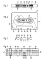
- a tape cassette 10 shown in FIGS. 1 and 2 has a cassette housing 12 of standardized type and size with two bobbindles 14 and 16 lying parallel to one another and axially parallel for a tape 18 attached to it with its ends.
- the tape reels are designed with an internal score 20 and 22, respectively, via which the tape runs at high speed alternately from one reel to the other reel with the aid of the drive hubs of the cassette drive.
- the audio tape 18 is guided along the end wall 28 of the cassette via deflecting means 24 and 26 which may be rotatably arranged in the cassette housing.
- the cassette housing 12 has through-openings 30 and 32 which are axially parallel to the reels and which receive a sound shaft which can be driven by a motor of the cassette drive when the cassette is inserted.
- pins which may be present and which protrude from the upper side of the cassette drive as tape guide means, pass through to the sound wave openings 30 and 32 with axially parallel through openings 34 and 36.
- a central opening 40 for the entry of a sound head, which is present for normal operation of the cassette drive, in particular a combined recording / playback head.
- the openings 40 to 44 in the cassette end wall 28 are each approximately the same size.
- openings 46 and 48 are cut out, which in known cassette drives accommodate, for example, a separate recording head or a tape guide element and are also referred to as reference holes.
- FIG. 3 shows schematically how the sound heads and rubber pressure rollers can be arranged next to one another in a drive provided in the device combination according to the invention with reference to the cutouts in the cassette end face 28 of an inserted cassette tape 10.
- a combination head 50 can be brought through the cassette recess 40 to the tape 18 for the usual recording and playback operation with known adjusting means.
- An erase head 52 for the recording tracks can enter the recess 42 in the cassette end wall 28.
- the magnetic heads 56 and 58 additionally present according to the invention are arranged on both sides of the combination head 50, the magnetic head 56 with a read / write system 76 through the reference opening 48, and the magnetic head 58 with an erasing system 78 through the reference opening 46 in the cassette end wall 28 Tape 18 can be moved in order to record, listen to or delete traffic information depending on the operating state.
- a rubber pressure roller for the audio shaft drive can preferably be controlled electromechanically in a cassette drive used according to the invention and, like the erasing head 52, can be moved towards the audio tape 18 through the window 42 of the cassette end face 28 in order to press it onto the audio shaft of the audio shaft drive for the drive.
- FIG. 4 shows an enlarged section of a cassette tape 18 with an arrangement of the recording tracks which is usual for stereo recordings.
- the recording of a stereo recording separated by channels R, L, which can be listened to in the direction of arrow I when the tape is in operation, is arranged on the lower half of the tape, while the upper half of the tape carries a corresponding recording with the stereo tracks RII and LII.
- a blank space 70 between the recordings on the upper and lower half of the tape forms the so-called turf, which is essential for the invention.
- traffic information with an announcement identifier is automatically recorded, which can then be deleted again with the aid of the delete system 78 of the magnetic head 58, without having to record or delete the upper and lower ones Half of the tape to impair existing stereo recordings.
- the systems 76 and 78 of the magnetic heads 56 and 58 present according to the invention are directly assigned to the lawn.
- the combination head 50 and the erasing head 52 are known heads, the combination head 50 in the embodiment shown having, for example, two magnet systems 80, 82 assigned to the two parallel tracks of a band half.
- the height of the housing of all magnetic heads used is preferably greater than the slurry te of the tape 18 selected so that the end face of the heads brought into contact with the tape acts advantageously as a tape guide.
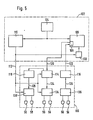
- FIG. 5 shows a block diagram of a recorder 100 which is connected to a traffic radio receiver 102 and receives the switching commands from it.
- the traffic radio receiver 102 contains a known HF / IF part 104 and an equally known NF part 106 with a tape connection 108.
- the NF signals at the output of the demodulator in the HF / IF part 104 are also known in the traffic radio receiver Traffic radio decoder 110 supplied and evaluated there as usual.
- the switching commands of the traffic radio decoder 110 are supplied to the recorder 100 via the command line 112, while the recording circuits 114 and playback circuits 116, which are constructed and switchable in a conventional manner, are, as usual, connected to the audio tape connector 108 of the traffic radio receiver via connecting lines 120, 122.
- the recorder comprises a quenching oscillator 118 which is known per se and which can be switched arbitrarily or automatically by the recording circuit.
- the recording circuit 114 and the playback circuit 116 also include the usual switches for arbitrarily switching on and off and for driving the drive. These usual switches can also be controlled in the receiving circuit 114 in the exemplary embodiment of the invention shown here via the command line 112.
- the output of the write amplifier in the recording circuit 114 is connected via a line 124 to a controllable changeover switch 134, to the control input of which the command line 112 is connected.
- the input of the sense amplifier in the playback circuit 116 is connected via the line 126 to a manually controllable changeover switch 136.
- the output of the quenching oscillator 118 is connected via a line 128 to a controllable changeover switch 138, the control input of which is also connected to the command line 112.
- a mute switch 130 for the LF part 106 of the traffic radio receiver 102 is also connected to the command line 112.
- the first connection of the switch 134 is connected to the write winding of the combination head 50, the second connection to the write winding of the magnetic head 56.
- the first connection of the switch 136 is connected to the read winding of the combination head 50, the second connection to the read winding of the magnetic head 56.
- the first connection of the switch 138 is connected to the erase head 52, the second connection to the magnetic head 58.
- the changeover switches 134, 136 connect the windings of the combination head 50 to the respective amplifiers 114, 116 and the changeover switch 138 connect the erase head 52 to the erase oscillator 118.
- a switch command is issued via the command line 112 the switches 134, 138 are given. In known traffic radio receivers, this switching command is fed only to the mute switch 130, which there causes the muting of the LF part 106 to be canceled.
- This switching command which is generated in a manner known per se, on the command line 112 causes the switches 134 and 130 to be switched over as soon as an announcement identifier is sent by the traffic radio station in addition to the normal LF signals.
- the recording circuit 114 is turned on via the command line 112. The traffic announcement transmitted by the transmitter is thus forcibly recorded on the lawn of the tape and an approximately previously recorded traffic announcement is deleted.
- the switch 136 must also be switched.
Landscapes
- Engineering & Computer Science (AREA)
- Multimedia (AREA)
- Signal Processing (AREA)
- Physics & Mathematics (AREA)
- General Physics & Mathematics (AREA)
- Recording Or Reproducing By Magnetic Means (AREA)
- Circuits Of Receivers In General (AREA)
- Input Circuits Of Receivers And Coupling Of Receivers And Audio Equipment (AREA)
Claims (4)
Priority Applications (1)
| Application Number | Priority Date | Filing Date | Title |
|---|---|---|---|
| AT81109518T ATE15730T1 (de) | 1980-12-02 | 1981-11-05 | Einrichtung zum speichern und abhoeren von verkehrsmeldungen. |
Applications Claiming Priority (2)
| Application Number | Priority Date | Filing Date | Title |
|---|---|---|---|
| DE19803045380 DE3045380A1 (de) | 1980-12-02 | 1980-12-02 | Verfahren und einrichtung zum speichern und abhoeren von verkehrsmeldungen |
| DE3045380 | 1980-12-02 |
Publications (2)
| Publication Number | Publication Date |
|---|---|
| EP0053734A1 EP0053734A1 (fr) | 1982-06-16 |
| EP0053734B1 true EP0053734B1 (fr) | 1985-09-18 |
Family
ID=6118097
Family Applications (1)
| Application Number | Title | Priority Date | Filing Date |
|---|---|---|---|
| EP81109518A Expired EP0053734B1 (fr) | 1980-12-02 | 1981-11-05 | Dispositif pour l'enregistrement et la restitution d'informations sur l'état du trafic routier |
Country Status (4)
| Country | Link |
|---|---|
| EP (1) | EP0053734B1 (fr) |
| JP (1) | JPS57123509A (fr) |
| AT (1) | ATE15730T1 (fr) |
| DE (1) | DE3045380A1 (fr) |
Families Citing this family (2)
| Publication number | Priority date | Publication date | Assignee | Title |
|---|---|---|---|---|
| US4713801A (en) * | 1986-02-20 | 1987-12-15 | Hale Arthur D | Radio-tape recorder for automotive use |
| DE3833452A1 (de) * | 1988-10-01 | 1990-04-05 | Grundig Emv | Verfahren zur vermeidung des versehentlichen ueberschreibens von auf einem videomagnetband aufgezeichneten videosignalabschnitten und videomagnetbandrecorder zur durchfuehrung dieses verfahrens |
Family Cites Families (6)
| Publication number | Priority date | Publication date | Assignee | Title |
|---|---|---|---|---|
| DE2032185C3 (de) * | 1970-06-30 | 1978-06-15 | Blaupunkt-Werke Gmbh, 3200 Hildesheim | Einrichtung zur Kennzeichnung, Auswahl und Aufzeichnung von Verkehrsdurchsagen |
| JPS5219527Y2 (fr) * | 1971-06-07 | 1977-05-06 | ||
| JPS5299303U (fr) * | 1976-01-26 | 1977-07-27 | ||
| JPS5255608A (en) * | 1975-10-31 | 1977-05-07 | Sanyo Electric Co Ltd | Magnetic recording and playback system |
| GB1500252A (en) * | 1976-05-20 | 1978-02-08 | Matsushita Electric Industrial Co Ltd | Magnetic tape and recording method therefor |
| DE2725050A1 (de) * | 1977-06-03 | 1978-12-21 | Hans Sukopp | Rundfunk-empfangsgeraet mit speichereinrichtung |
-
1980
- 1980-12-02 DE DE19803045380 patent/DE3045380A1/de active Granted
-
1981
- 1981-11-05 EP EP81109518A patent/EP0053734B1/fr not_active Expired
- 1981-11-05 AT AT81109518T patent/ATE15730T1/de not_active IP Right Cessation
- 1981-12-02 JP JP56192992A patent/JPS57123509A/ja active Pending
Non-Patent Citations (1)
| Title |
|---|
| FUNKSCHAU, Band 59, 1. Dezember 1978, MÜNCHEN (DE) D. HEISS: "ARI-Infothek im Auto- eine Entwicklungsstudie" Seite 1263 * |
Also Published As
| Publication number | Publication date |
|---|---|
| DE3045380A1 (de) | 1982-07-01 |
| JPS57123509A (en) | 1982-08-02 |
| DE3045380C2 (fr) | 1989-06-22 |
| ATE15730T1 (de) | 1985-10-15 |
| EP0053734A1 (fr) | 1982-06-16 |
Similar Documents
| Publication | Publication Date | Title |
|---|---|---|
| DE69427260T2 (de) | Radiodatenempfänger mit durch Programmartdaten gesteuerter Stromversorgungsschaltung | |
| DE69333123T2 (de) | Elektronische Vorrichtung | |
| DE3121034A1 (de) | Ukw-empfaenger | |
| DE2930509A1 (de) | Verkehrsfunksystem | |
| DE4222877C2 (de) | Verfahren zur Übertragung regional unterschiedlicher Informationen in Gleichwellennetzen und Empfänger zum Durchführen der empfangsseitigen Maßnahmen | |
| EP0053734B1 (fr) | Dispositif pour l'enregistrement et la restitution d'informations sur l'état du trafic routier | |
| EP0878906A1 (fr) | Récepteur de radio | |
| EP0166861A2 (fr) | Procédé pour l'enregistrement d'un signal de télévision | |
| DE4408930A1 (de) | Kombinationsgerät | |
| DE4224598C2 (de) | Radioempfänger mit einem Kassettengerät | |
| EP1219027B1 (fr) | Procede et dispositif permettant de faire fonctionner un dispositif audio dans un vehicule automobile | |
| DE3124858C2 (de) | Radio-Kassettenrecorder-Kombination | |
| DE3028691C2 (de) | Magnetbandgerät | |
| DE3806972A1 (de) | Vorrichtung zum empfangen, erkennen und wiedergeben von verkehrsfunkansagen | |
| DE4230600C2 (de) | Rundfunkempfänger | |
| DE3805438A1 (de) | System zur aufzeichnung und wiedergabe von videosignalen | |
| EP0795974B1 (fr) | Méthode et récepteur pour la production de messages parlés et méthode pour la transmission de messages parlés | |
| DE69709186T2 (de) | Aufzeichnungs- und wiedergabegerät mit teletextaufzeichnung | |
| DE2807483A1 (de) | Verfahren zur information ueber strassen- und verkehrszustaende und vorrichtung zur durchfuehrung dieses verfahrens | |
| EP0790719B1 (fr) | Méthode et récepteur pour la réception et reproduction de messages routières codés numériques | |
| DE2108731A1 (de) | Auto Cassetten Mehrspur Tonbandgerat in Zwei und Vierkanal Achtspur Technik | |
| DE3706822A1 (de) | Verfahren zum speichern von sendungen | |
| EP0364998B1 (fr) | Appareil d'enregistrement-reproduction pour l'enregistrement et/ou la reproduction de façon continue de messages | |
| DE3347231C2 (fr) | ||
| DE3905122C1 (fr) |
Legal Events
| Date | Code | Title | Description |
|---|---|---|---|
| PUAI | Public reference made under article 153(3) epc to a published international application that has entered the european phase |
Free format text: ORIGINAL CODE: 0009012 |
|
| AK | Designated contracting states |
Designated state(s): AT CH FR GB IT |
|
| 17P | Request for examination filed |
Effective date: 19820920 |
|
| ITF | It: translation for a ep patent filed | ||
| GRAA | (expected) grant |
Free format text: ORIGINAL CODE: 0009210 |
|
| AK | Designated contracting states |
Designated state(s): AT CH FR GB IT LI |
|
| REF | Corresponds to: |
Ref document number: 15730 Country of ref document: AT Date of ref document: 19851015 Kind code of ref document: T |
|
| ET | Fr: translation filed | ||
| GBPC | Gb: european patent ceased through non-payment of renewal fee | ||
| PLBE | No opposition filed within time limit |
Free format text: ORIGINAL CODE: 0009261 |
|
| STAA | Information on the status of an ep patent application or granted ep patent |
Free format text: STATUS: NO OPPOSITION FILED WITHIN TIME LIMIT |
|
| 26N | No opposition filed | ||
| GBDL | Gb: delete "european patent ceased" from journal |
Free format text: 5080, PAGE 4896 |
|
| PGFP | Annual fee paid to national office [announced via postgrant information from national office to epo] |
Ref country code: AT Payment date: 19890911 Year of fee payment: 9 |
|
| PGFP | Annual fee paid to national office [announced via postgrant information from national office to epo] |
Ref country code: GB Payment date: 19891031 Year of fee payment: 9 |
|
| PGFP | Annual fee paid to national office [announced via postgrant information from national office to epo] |
Ref country code: FR Payment date: 19891129 Year of fee payment: 9 |
|
| ITTA | It: last paid annual fee | ||
| PGFP | Annual fee paid to national office [announced via postgrant information from national office to epo] |
Ref country code: CH Payment date: 19900216 Year of fee payment: 9 |
|
| PG25 | Lapsed in a contracting state [announced via postgrant information from national office to epo] |
Ref country code: GB Effective date: 19901105 Ref country code: AT Effective date: 19901105 |
|
| PG25 | Lapsed in a contracting state [announced via postgrant information from national office to epo] |
Ref country code: LI Effective date: 19901130 Ref country code: CH Effective date: 19901130 |
|
| GBPC | Gb: european patent ceased through non-payment of renewal fee | ||
| PG25 | Lapsed in a contracting state [announced via postgrant information from national office to epo] |
Ref country code: FR Effective date: 19910731 |
|
| REG | Reference to a national code |
Ref country code: CH Ref legal event code: PL |
|
| REG | Reference to a national code |
Ref country code: FR Ref legal event code: ST |