EP0053746A2 - Procédé et installation pour optimiser le bilan thermique de bâtiments - Google Patents
Procédé et installation pour optimiser le bilan thermique de bâtiments Download PDFInfo
- Publication number
- EP0053746A2 EP0053746A2 EP81109815A EP81109815A EP0053746A2 EP 0053746 A2 EP0053746 A2 EP 0053746A2 EP 81109815 A EP81109815 A EP 81109815A EP 81109815 A EP81109815 A EP 81109815A EP 0053746 A2 EP0053746 A2 EP 0053746A2
- Authority
- EP
- European Patent Office
- Prior art keywords
- heat
- bottom layer
- layer
- heat dissipation
- energy
- Prior art date
- Legal status (The legal status is an assumption and is not a legal conclusion. Google has not performed a legal analysis and makes no representation as to the accuracy of the status listed.)
- Withdrawn
Links
Images


Classifications
-
- F—MECHANICAL ENGINEERING; LIGHTING; HEATING; WEAPONS; BLASTING
- F24—HEATING; RANGES; VENTILATING
- F24D—DOMESTIC- OR SPACE-HEATING SYSTEMS, e.g. CENTRAL HEATING SYSTEMS; DOMESTIC HOT-WATER SUPPLY SYSTEMS; ELEMENTS OR COMPONENTS THEREFOR
- F24D11/00—Central heating systems using heat accumulated in storage masses
- F24D11/02—Central heating systems using heat accumulated in storage masses using heat pumps
- F24D11/0214—Central heating systems using heat accumulated in storage masses using heat pumps water heating system
- F24D11/0221—Central heating systems using heat accumulated in storage masses using heat pumps water heating system combined with solar energy
-
- F—MECHANICAL ENGINEERING; LIGHTING; HEATING; WEAPONS; BLASTING
- F24—HEATING; RANGES; VENTILATING
- F24S—SOLAR HEAT COLLECTORS; SOLAR HEAT SYSTEMS
- F24S20/00—Solar heat collectors specially adapted for particular uses or environments
- F24S20/60—Solar heat collectors integrated in fixed constructions, e.g. in buildings
- F24S20/67—Solar heat collectors integrated in fixed constructions, e.g. in buildings in the form of roof constructions
-
- Y—GENERAL TAGGING OF NEW TECHNOLOGICAL DEVELOPMENTS; GENERAL TAGGING OF CROSS-SECTIONAL TECHNOLOGIES SPANNING OVER SEVERAL SECTIONS OF THE IPC; TECHNICAL SUBJECTS COVERED BY FORMER USPC CROSS-REFERENCE ART COLLECTIONS [XRACs] AND DIGESTS
- Y02—TECHNOLOGIES OR APPLICATIONS FOR MITIGATION OR ADAPTATION AGAINST CLIMATE CHANGE
- Y02A—TECHNOLOGIES FOR ADAPTATION TO CLIMATE CHANGE
- Y02A30/00—Adapting or protecting infrastructure or their operation
- Y02A30/60—Planning or developing urban green infrastructure
-
- Y—GENERAL TAGGING OF NEW TECHNOLOGICAL DEVELOPMENTS; GENERAL TAGGING OF CROSS-SECTIONAL TECHNOLOGIES SPANNING OVER SEVERAL SECTIONS OF THE IPC; TECHNICAL SUBJECTS COVERED BY FORMER USPC CROSS-REFERENCE ART COLLECTIONS [XRACs] AND DIGESTS
- Y02—TECHNOLOGIES OR APPLICATIONS FOR MITIGATION OR ADAPTATION AGAINST CLIMATE CHANGE
- Y02B—CLIMATE CHANGE MITIGATION TECHNOLOGIES RELATED TO BUILDINGS, e.g. HOUSING, HOUSE APPLIANCES OR RELATED END-USER APPLICATIONS
- Y02B10/00—Integration of renewable energy sources in buildings
- Y02B10/20—Solar thermal
-
- Y—GENERAL TAGGING OF NEW TECHNOLOGICAL DEVELOPMENTS; GENERAL TAGGING OF CROSS-SECTIONAL TECHNOLOGIES SPANNING OVER SEVERAL SECTIONS OF THE IPC; TECHNICAL SUBJECTS COVERED BY FORMER USPC CROSS-REFERENCE ART COLLECTIONS [XRACs] AND DIGESTS
- Y02—TECHNOLOGIES OR APPLICATIONS FOR MITIGATION OR ADAPTATION AGAINST CLIMATE CHANGE
- Y02B—CLIMATE CHANGE MITIGATION TECHNOLOGIES RELATED TO BUILDINGS, e.g. HOUSING, HOUSE APPLIANCES OR RELATED END-USER APPLICATIONS
- Y02B10/00—Integration of renewable energy sources in buildings
- Y02B10/70—Hybrid systems, e.g. uninterruptible or back-up power supplies integrating renewable energies
-
- Y—GENERAL TAGGING OF NEW TECHNOLOGICAL DEVELOPMENTS; GENERAL TAGGING OF CROSS-SECTIONAL TECHNOLOGIES SPANNING OVER SEVERAL SECTIONS OF THE IPC; TECHNICAL SUBJECTS COVERED BY FORMER USPC CROSS-REFERENCE ART COLLECTIONS [XRACs] AND DIGESTS
- Y02—TECHNOLOGIES OR APPLICATIONS FOR MITIGATION OR ADAPTATION AGAINST CLIMATE CHANGE
- Y02B—CLIMATE CHANGE MITIGATION TECHNOLOGIES RELATED TO BUILDINGS, e.g. HOUSING, HOUSE APPLIANCES OR RELATED END-USER APPLICATIONS
- Y02B30/00—Energy efficient heating, ventilation or air conditioning [HVAC]
- Y02B30/12—Hot water central heating systems using heat pumps
-
- Y—GENERAL TAGGING OF NEW TECHNOLOGICAL DEVELOPMENTS; GENERAL TAGGING OF CROSS-SECTIONAL TECHNOLOGIES SPANNING OVER SEVERAL SECTIONS OF THE IPC; TECHNICAL SUBJECTS COVERED BY FORMER USPC CROSS-REFERENCE ART COLLECTIONS [XRACs] AND DIGESTS
- Y02—TECHNOLOGIES OR APPLICATIONS FOR MITIGATION OR ADAPTATION AGAINST CLIMATE CHANGE
- Y02E—REDUCTION OF GREENHOUSE GAS [GHG] EMISSIONS, RELATED TO ENERGY GENERATION, TRANSMISSION OR DISTRIBUTION
- Y02E10/00—Energy generation through renewable energy sources
- Y02E10/40—Solar thermal energy, e.g. solar towers
Definitions
- the invention relates to a method for optimizing the heat balance of buildings with flat or pitched roofs, which are covered with a moistenable, preferably greenable, floor layer above a roof skin, and a device related thereto.
- Floor layers serving as roof coverings have proven to be very advantageous in several respects, in particular in connection with planting, and are being used to an increasing extent. They provide good heat and cold protection as well as weather protection for the roof structure underneath. In addition, roof plantings lead to a significant improvement in the environmental climate, especially in densely populated areas.
- the bottom layer is a weight and cost reasons has a relatively limited thickness and thus a temporary buffer effect, it is inevitable that in predominantly warm seasons an undesirable predominant heat flow from outside via the roof into the interior of the building takes place, while in predominantly cold seasons and at night a roof-related energy loss must be accepted.
- the excess heat caused by the environment leads to an undesired increase in temperature in the building, and in the second case, the heat loss which occurs must be compensated for keeping the temperature constant.
- the object of the present invention is therefore to improve the heat balance of buildings with such roof-floor layers and to avoid the disadvantages mentioned with relatively simple means by optimizing the energy conditions.
- a method of the type mentioned in the preamble according to the invention is characterized in that the bottom layer is used as a heat-conducting heat absorber and store for external heat energy and optionally for thermal energy flowing out of the building, in particular via the roof skin, and for it Heating purposes and / or for cooling the building, thermal energy is extracted as primary energy and / or as recovery energy.
- This measure is suitable for both thick and thin soil layers and is extremely simple since the entire soil layer is used in its function as a heat absorber and storage. If the floor layer is heated by the outside temperature or by solar radiation, heat energy can be used to heat the building and / or to heat water be withdrawn.
- the room temperature can be kept at a lower level, especially in summer.
- An increased heat energy withdrawal also leads to a noticeable cooling of the floor layer, which also improves the indoor climate in the building, especially in summer.
- the primary energy entering the soil layer from the outside can be used much more cheaply by deliberately removing it and by supplying it to the individual heat consumers as required.
- the floor layer absorber enables the heat loss flowing out of the building, for example via the roof, to be recovered, which can thus be fed back into the building's heating circuit.
- the fact that the soil layer which can be moistened is thermally conductive leads to a good heat storage thereof and enables simple means for extracting heat energy, without this influencing the plantability of the soil layer.
- the heat energy withdrawn be stored.
- the primary energy or the recovery energy obtained can be used and called up as required, for example primarily in summer for hot water preparation and in winter mainly for heating buildings.
- a particularly advantageous embodiment of the method according to the invention is characterized in that the heat energy extracted is brought to a higher temperature level by means of a heat pump system.
- the extraction of the thermal energy is preferably controlled or regulated depending on the environment and / or demand. For example, in the warm season and especially when the sun is shining, increased heat removal may be appropriate in order to cool the floor layer and thus achieve a more favorable indoor climate in the building. At the same time, there is a large amount of thermal energy, for example for heating domestic water. In the cool season, on the other hand, just as much heat can be extracted from the floor layer as is required for heating purposes or for heat recovery of the heat loss that occurs. The control or regulation of the heat extraction can take place depending on the measured and entered operating parameters.
- the floor layer is specifically or directly supplied with heat energy from other parts of the building which emit heat loss.
- heat loss generated in the chimney or chimney area is supplied via the exhaust gases to the bottom layer and / or transferred to a flow medium, in particular air, and is fed to the bottom layer by means of this. In this way, the combustion waste gas heat that would otherwise be lost can be at least partially recovered, with multiple use of the bottom layer absorber that is present anyway.
- waste heat can be used in practically any burning point that works, for example, with wood, coal, oil, gas or the like and on the one hand for room heating and on the other hand for thermal charging the bottom layer provides.
- exhaust-gas-heated air in particular using its thermally induced self-flow, is passed directly underneath the bottom layer and in a heat exchange relationship evenly distributed through a drainage or air layer.
- the air-permeable drainage used at the same time as a means for discharging the heated air, a constant heat exchange taking place between the heated air and the bottom layer.
- a device for optimizing the heat balance of buildings with flat or pitched roofs is further characterized by a roof covering with a humidifiable bottom layer working as a heat-conducting heat absorber and storage and by a heat dissipation agent in direct thermal contact with the latter.
- Such thermal building equipment is relatively inexpensive in comparison to conventional energy roofs and, taking into account the above statements, is considerably more advantageous in many respects. For example, this allows the optical conditions, the environmental and indoor climate conditions and the energetic properties to be combined in an excellent manner. With optimal weather and heat protection, this results in an ecologically extremely valuable energy roof.
- the device preferably has a pipe system integrated in the bottom layer and through which a heat dissipation medium, such as freeze-protected water, flows as a heat dissipation means.
- a heat dissipation medium such as freeze-protected water
- the device preferably has a pipe system integrated in the bottom layer and through which a heat dissipation medium, such as freeze-protected water, flows as a heat dissipation means.
- a heat dissipation medium such as freeze-protected water
- This heat dissipation agent can also be the carrier for the bottom layer and is then to be provided with perforations if excessive water is to be discharged downward from the bottom layer.
- metallic floor layer inserts such as mats or the like, can be used as heat-conducting members. These can also be connected to the heat dissipation means and can be designed, for example, as fins of a pipe system. Such members or materials which favor the heat conduction of the bottom layer enable a further reduction in the heat extraction points and avoid the necessary irrigation of the bottom layer in order to achieve adequate heat conduction.
- the outward-facing surface of the bottom layer should be oriented at a favorable angle of incidence for absorbing solar energy.
- the steps of the sawtooth shape are dimensionally stabilized by heat dissipation means.
- the heat dissipation means have a multiple function, since on the one hand they serve to dissipate heat and on the other hand to hold the sawtooth-shaped bottom layer.
- they can also provide for direct heat absorption.
- a base layer support which receives the base layer is of a sawtooth shape. This results in the sawtooth shape of the base layer on the carrier, which is favorable for solar radiation. It is also possible that the sawtooth-shaped base layer carrier is already designed as a heat dissipation means. As a result, further links within the bottom layer can be omitted.
- the heat dissipation means and / or the bottom layer support for the bottom layer are designed to be non-slip in the case of sloping roofs. This measure avoids additional holding means for the bottom layer, and it is also possible, for example, to use a sawtooth-shaped bottom layer support.
- the optimal angle of sunshine can be improved in the case of inclined roofs that are too steep and too flat.
- the floor layer is arranged above a drainage located above the roof skin.
- a water-permeable, preferably filtering, heat-dissipating agent as a separation between the bottom layer and the drainage.
- the device has a heating center which connects the heat dissipation means to heat consumers and a control or regulating device which actuates them as a function of operating parameters, such as the temperature of the bottom layer or the heat dissipation medium.
- the heating center can be provided with a heat accumulator and / or a heat exchanger and / or a heat pump. Such a device enables optimal energy utilization and can be connected to a normal heating system if necessary.
- a pipe system which conducts a fluid heated by heat loss through the bottom layer and / or through a drainage or air layer located underneath.
- This pipe system enables multiple use of the bottom layer heat absorber and recovery of otherwise unused heat energy.
- a particularly expedient embodiment in this regard is characterized by an exhaust gas / air heat exchanger in a chimney or chimney area with a fresh air inlet and a flow distributor opening into the drainage or air layer and / or guided through the bottom layer. Regardless of which, lige type of the focal point, the thermal energy present in the exhaust gas can thus be at least partially recovered by simply feeding it to the bottom layer.
- a particularly simple embodiment which is particularly suitable for a sloping roof, has an ascending heat exchanger with a lower fresh air inlet, as well as an upper flow distributor opening into an obliquely ascending drainage or air layer and an upper air outlet of the drainage or air layer.
- a thermally induced self-flow results, and additional forced flow means can be dispensed with.
- an exhaust gas is present as the refractory, gas-tight and weather-resistant pipe system which conducts the fluid from a chimney or chimney area. This directs the warm or hot exhaust gas directly through the area of the drainage or the bottom layer, so that an intermediate heat exchanger can be omitted.
- Such a measure is particularly expedient when there is largely residue-free combustion and the cleaning of exhaust gas ducts can essentially be dispensed with, as in the case of a combustion point working with gaseous fuels.
- a thermally induced flow can be used to supply the heat loss to the soil layer.
- additional elements such as fans or the like.
- the heat loss can be fed directly to the heat dissipation means without having to bridge several thermal contact resistances.
- a particularly effective system is present when the pipe system through which the exhaust gas flows runs in the immediate vicinity of the heat dissipation agent.
- a planting which allows or promotes the heat absorption of the soil layer and in particular a wind-induced surface cooling of the soil layer should be selected.
- grass-like, that is to say essentially leafless, planting allows the solar radiation to strike the ground layer largely unhindered and at the same time prevents a cooling wind flow in the boundary region near the ground.
- a directly heat-absorbing planting is also conceivable, so that the heat energy passes indirectly from the outside through the planting into the soil layer and is held in the soil layer as a result of the thermally protective planting.
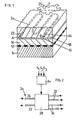
- a load-bearing roof structure 10 which can already contain sufficient thermal insulation, is covered on the top by a roof skin 12.
- a drainage 14 which can consist, for example, of coarse-grained gravel, drainage plates or another suitable material.
- a water-permeable floor layer support 16 located above the drainage 14 serves to receive a floor layer 18 arranged above it and preferably has a filtering effect so that the water flowing out of the floor layer 18 into the drainage 14 is largely free of soil components.
- the soil layer 18 can consist of conventional soil or of an artificial soil material that is suitable for planting.
- the thickness of the bottom layer 18 can be adapted to the respective conditions and for example about 10 to 20 cm.
- a heat dissipation means 20 is embedded, which in the present case consists of a metallic pipe coil shown in broken lines, which has an inlet 22 and an outlet 24 for a heat dissipation medium, such as freeze-protected water, flowing in the direction of the arrows A, B. Due to the heat conduction of the bottom layer 18 and the direct thermal contact with the heat dissipation means 20 and the heat dissipation medium located therein, an effective heat removal is ensured in the entire bottom layer 18 despite the mutual distances between the pipe sections of the pipe coil.
- this acts as a heat-conducting heat absorber and store, from which heat energy can be extracted in a manner appropriate to the needs via the heat-dissipating means 20. Since the coil of the heat dissipation means 20 is located only in individual areas within the soil layer 18, a possible vegetation 26 is in no way impaired.
- the bottom layer support 16 itself is designed as a large-area heat dissipation means.
- the inlets and outlets 22, 24 of the heat dissipation means 20 are connected in a circular manner to a heating center 28, which preferably comprises a heat pump and a suitable f .. Storage for higher temperature water generated by the heat pump contains.
- the heating center 28 is connected to a control or regulating device 30, which ensures suitable control or regulation via measured and / or input operating parameters S1, S 2 , S 3 .
- the operating parameters can be, for example, temperatures of the building, the environment and the floor layer.
- the thermal energy stored in the heating center 28 can be distributed as required to a heating circuit 32 and / or a process water circuit 34.
- a bottom layer 18 with a sawtooth-shaped stepped surface 18-1 is located on a horizontally arranged bottom layer support 16.
- the steps of the sawtooth shape are limited in the present case by a suitable coil of heat dissipation means 20-1 to stabilize the shape.
- a suitable coil of heat dissipation means 20-1 to stabilize the shape.
- a sawtooth-shaped base layer support 16-1 is used instead, on which the base layer 18 is applied in approximately the same thickness, in contrast to FIG. 3.
- a sawtooth-shaped surface 18-1 is created with an optimal orientation for solar radiation.
- the heat dissipation means 20, for example a pipe coil, can be shown in FIG Bottom layer 18 can be integrated.
- the bottom layer support 16-1 itself is designed as a heat dissipation means.
- FIG. 5 shows an embodiment of the device according to the invention in connection with a sloping roof.
- a supporting roof structure 10 in this regard which is covered with a roof skin 12, there is a drainage 14 which rises from the eaves side to the ridge side and forms an air layer.
- the floor layer 18 with the heat dissipation means 20 is arranged via a floor layer support, not shown in the present case is again shown as a coil.
- a chimney 38 connected to a chimney 36 or another fireplace there is an ascending, highly effective heat exchanger 40 with a fresh air inlet 42 on the underside.
- the heat exchanger 40 opens into an air distributor 44, which ensures that the thermally induced forced flow of the heat exchanger 40 Air heated by the hot exhaust gas is distributed as evenly as possible over the drainage 14 or air layer. The warm air entering this flows through the drainage 14 or air layer in order to emerge from it from an air outlet 46 on the ridge side. Accordingly, the embodiment shown in FIG. 5 does not require any forced fluid, such as a fan or the like. Rather, the air heated by heat exchange is automatically directed upwards and brought into heat exchange relationship with the bottom layer or the heat dissipation means 20.
- forced fluids such as fans or the like
- the fluid can also be the exhaust gas from the focal point directly and can be passed through the bottom layer through a closed pipe system.
- the pipe system in the immediate vicinity and largely in direct thermal contact with the heat dissipation means 20.
- the surface temperature in the adjacent soil layer region does not exceed approximately 30 to 35 ° C, which can be easily achieved by known, weather-resistant and asbestos-suitable cement-asbestos profiles.
- the invention enables a very simple, inexpensive creation of extremely advantageous energy roofs, which for the first time combine ecological and economic aspects in an extremely effective manner.
- the detailed design of such an energy roof can be varied in many ways and can be adapted to the respective installation conditions and requirements. It is important, however, that a normally relatively thin, preferably greenable floor layer roof covering is used as a heat-conducting heat absorber and storage device, which receives heat energy as primary energy and / or as required is withdrawn as heat recovery energy.
- the possible vegetation of the soil layer can be selected in terms of type and density so that optimal energetic conditions and possibly further improvements with regard to a storing heat absorption result.
Landscapes
- Engineering & Computer Science (AREA)
- Life Sciences & Earth Sciences (AREA)
- Sustainable Development (AREA)
- Sustainable Energy (AREA)
- Physics & Mathematics (AREA)
- Thermal Sciences (AREA)
- Chemical & Material Sciences (AREA)
- Combustion & Propulsion (AREA)
- Mechanical Engineering (AREA)
- General Engineering & Computer Science (AREA)
- Building Environments (AREA)
Applications Claiming Priority (2)
| Application Number | Priority Date | Filing Date | Title |
|---|---|---|---|
| DE19803044169 DE3044169A1 (de) | 1980-11-24 | 1980-11-24 | Verfahren und einrichtung zum optimieren des waermehaushalts von gebaeuden |
| DE3044169 | 1980-11-24 |
Publications (2)
| Publication Number | Publication Date |
|---|---|
| EP0053746A2 true EP0053746A2 (fr) | 1982-06-16 |
| EP0053746A3 EP0053746A3 (fr) | 1982-12-08 |
Family
ID=6117413
Family Applications (1)
| Application Number | Title | Priority Date | Filing Date |
|---|---|---|---|
| EP81109815A Withdrawn EP0053746A3 (fr) | 1980-11-24 | 1981-11-21 | Procédé et installation pour optimiser le bilan thermique de bâtiments |
Country Status (2)
| Country | Link |
|---|---|
| EP (1) | EP0053746A3 (fr) |
| DE (1) | DE3044169A1 (fr) |
Cited By (2)
| Publication number | Priority date | Publication date | Assignee | Title |
|---|---|---|---|---|
| GB2516260A (en) * | 2013-07-16 | 2015-01-21 | Russell Croston Aubusson | A roof structure for heating and cooling a building |
| WO2021165824A1 (fr) * | 2020-02-20 | 2021-08-26 | Siegenthaler Andy | Système d'échange thermique pour la régulation thermique d'un bâtiment |
Families Citing this family (2)
| Publication number | Priority date | Publication date | Assignee | Title |
|---|---|---|---|---|
| DE3505947A1 (de) * | 1985-02-21 | 1986-08-21 | Hölter, Heinz, Dipl.-Ing., 4390 Gladbeck | Oekologisches dach mit waermerueckgewinnung |
| DE3625829A1 (de) * | 1986-07-30 | 1988-02-11 | Max Dr Ing Dr Mengeringhausen | Heizungsanlage |
Family Cites Families (4)
| Publication number | Priority date | Publication date | Assignee | Title |
|---|---|---|---|---|
| SE420761B (sv) * | 1975-11-19 | 1981-10-26 | Teknoterm Systems Ab | Anordning for uppfangning av verme- och solenergi vid ett hus |
| DE2557895A1 (de) * | 1975-12-22 | 1977-06-30 | Kabel Metallwerke Ghh | Vorrichtung zum beheizen von gebaeuden mittels einer waermepumpenanlage |
| DE2821832A1 (de) * | 1978-05-19 | 1979-11-29 | Heinz Hoelter | Sonnenkollektor-dachhaut mit gewellter oberflaeche |
| DE3011457C2 (de) * | 1980-03-25 | 1984-11-29 | J.A. Braun Gmbh & Co Kg, 7000 Stuttgart | Vorrichtung an Gebäuden zur Energiegewinnung |
-
1980
- 1980-11-24 DE DE19803044169 patent/DE3044169A1/de not_active Withdrawn
-
1981
- 1981-11-21 EP EP81109815A patent/EP0053746A3/fr not_active Withdrawn
Cited By (3)
| Publication number | Priority date | Publication date | Assignee | Title |
|---|---|---|---|---|
| GB2516260A (en) * | 2013-07-16 | 2015-01-21 | Russell Croston Aubusson | A roof structure for heating and cooling a building |
| WO2021165824A1 (fr) * | 2020-02-20 | 2021-08-26 | Siegenthaler Andy | Système d'échange thermique pour la régulation thermique d'un bâtiment |
| CH717158A1 (fr) * | 2020-02-20 | 2021-08-31 | Siegenthaler Andy | Système d'échange thermique pour la régulation thermique d'un bâtiment. |
Also Published As
| Publication number | Publication date |
|---|---|
| EP0053746A3 (fr) | 1982-12-08 |
| DE3044169A1 (de) | 1982-06-24 |
Similar Documents
| Publication | Publication Date | Title |
|---|---|---|
| DE69031540T2 (de) | Vorrichtung zur Vorwärmung von Luft zur Gebäudelüftung | |
| EP0850388B1 (fr) | Installation de production d'energie pour batiments | |
| DE2721467C2 (de) | Vorfabriziertes Fassadenelement mit einem auf der Innenseite angeordneten Heizkörper | |
| CH645424A5 (en) | Roofing tile for a roof arrangement for the utilisation of solar energy | |
| DE10023424A1 (de) | Anlage zur Erzeugung elektrischer Energie aus Sonnenenergie | |
| DE3740618C2 (fr) | ||
| DE202006011482U1 (de) | Heiz- und Warmwassersystem für Gebäude unter Nutzung eines solarenergieversorgten Erdwärmespeichers mit oder ohne Infrarotstrahlungselement mit integrierter Sole-Wasser Wärmepumpe | |
| EP0053746A2 (fr) | Procédé et installation pour optimiser le bilan thermique de bâtiments | |
| DE102007025103A1 (de) | Verfahren und Vorrichtung zur Nutzung von Wärme aus einem Flächenkollektor an einem Gebäude | |
| CH651345A5 (de) | Energiedach. | |
| EP1330579A1 (fr) | Batiment a faible consommation d'energie | |
| WO1999042766A1 (fr) | Dispositif pour capter l'energie solaire sur des batiments | |
| DE2557895A1 (de) | Vorrichtung zum beheizen von gebaeuden mittels einer waermepumpenanlage | |
| DE2808814A1 (de) | Verfahren und vorrichtung zum speichern und distribuieren von durch sonnenenergie aufgewaermter luft | |
| EP0018543A1 (fr) | Collecteur d'énergie solaire | |
| DE2623166A1 (de) | Sonnenheizungsverfahren fuer wohnhaeuser, im prinzip mit einer einzigen ebene | |
| DE3101199A1 (de) | Vorrichtung zum erwaermen und zum in erwaermtem zustand speichern von wasser | |
| DE3006905A1 (de) | Energieabsorberanlage | |
| EP0151993B1 (fr) | Elément d'une paroi extérieure pour un bâtiment | |
| DE3006083C1 (de) | Klima-Gewaechshaus | |
| DE3016436A1 (de) | Zu einer schallschutzwand, vorzugsweise zwischen pfosten anordenbare schallschutzelemente | |
| DE102006020535A1 (de) | Vorrichtung zum Aufnehmen und Speichern von Sonnenenergie | |
| DE202023002105U1 (de) | Fassadenmodul zur Regen-, Grau- und Frischwasserrückhaltung für eine verbesserte thermische Behaglichkeit im Innen- und Außenraum durch Verdunstungskühlung sowie eine erhöhte Wärmekapazität der Gebäudehülle | |
| DE2922652A1 (de) | Dacheindeckungsanordnung | |
| EP2116776A1 (fr) | Climatisation d'immeuble et procédé pour tempérer l'air dans un immeuble |
Legal Events
| Date | Code | Title | Description |
|---|---|---|---|
| PUAI | Public reference made under article 153(3) epc to a published international application that has entered the european phase |
Free format text: ORIGINAL CODE: 0009012 |
|
| AK | Designated contracting states |
Designated state(s): AT BE CH DE FR GB IT LU NL SE |
|
| PUAL | Search report despatched |
Free format text: ORIGINAL CODE: 0009013 |
|
| AK | Designated contracting states |
Designated state(s): AT BE CH DE FR GB IT LU NL SE |
|
| STAA | Information on the status of an ep patent application or granted ep patent |
Free format text: STATUS: THE APPLICATION IS DEEMED TO BE WITHDRAWN |
|
| 18D | Application deemed to be withdrawn |
Effective date: 19831116 |