EP0053836B1 - Dispositif et procédé de purification d'un courant gazeux - Google Patents
Dispositif et procédé de purification d'un courant gazeux Download PDFInfo
- Publication number
- EP0053836B1 EP0053836B1 EP81110257A EP81110257A EP0053836B1 EP 0053836 B1 EP0053836 B1 EP 0053836B1 EP 81110257 A EP81110257 A EP 81110257A EP 81110257 A EP81110257 A EP 81110257A EP 0053836 B1 EP0053836 B1 EP 0053836B1
- Authority
- EP
- European Patent Office
- Prior art keywords
- sub
- gas stream
- chamber
- venturi
- container
- Prior art date
- Legal status (The legal status is an assumption and is not a legal conclusion. Google has not performed a legal analysis and makes no representation as to the accuracy of the status listed.)
- Expired
Links
- 238000000034 method Methods 0.000 title claims description 6
- 238000000746 purification Methods 0.000 title 1
- 239000007789 gas Substances 0.000 claims description 41
- 239000007788 liquid Substances 0.000 claims description 25
- 238000005406 washing Methods 0.000 claims description 22
- 238000005192 partition Methods 0.000 claims description 19
- NINIDFKCEFEMDL-UHFFFAOYSA-N Sulfur Chemical compound [S] NINIDFKCEFEMDL-UHFFFAOYSA-N 0.000 claims description 5
- RWSOTUBLDIXVET-UHFFFAOYSA-N Dihydrogen sulfide Chemical compound S RWSOTUBLDIXVET-UHFFFAOYSA-N 0.000 claims description 4
- 150000001875 compounds Chemical class 0.000 claims description 4
- 238000006073 displacement reaction Methods 0.000 claims description 3
- 238000005191 phase separation Methods 0.000 claims description 2
- 239000005864 Sulphur Substances 0.000 claims 3
- 239000012530 fluid Substances 0.000 claims 1
- 239000003599 detergent Substances 0.000 description 3
- 229910000037 hydrogen sulfide Inorganic materials 0.000 description 3
- 238000004140 cleaning Methods 0.000 description 2
- 238000006477 desulfuration reaction Methods 0.000 description 2
- 230000023556 desulfurization Effects 0.000 description 2
- 229910052717 sulfur Inorganic materials 0.000 description 2
- 239000011593 sulfur Substances 0.000 description 2
- 239000003795 chemical substances by application Substances 0.000 description 1
- 238000001816 cooling Methods 0.000 description 1
- 230000003009 desulfurizing effect Effects 0.000 description 1
- 239000000428 dust Substances 0.000 description 1
- 238000000926 separation method Methods 0.000 description 1
- 150000003464 sulfur compounds Chemical class 0.000 description 1
- 239000012808 vapor phase Substances 0.000 description 1
Images
Classifications
-
- B—PERFORMING OPERATIONS; TRANSPORTING
- B01—PHYSICAL OR CHEMICAL PROCESSES OR APPARATUS IN GENERAL
- B01D—SEPARATION
- B01D53/00—Separation of gases or vapours; Recovering vapours of volatile solvents from gases; Chemical or biological purification of waste gases, e.g. engine exhaust gases, smoke, fumes, flue gases, aerosols
- B01D53/14—Separation of gases or vapours; Recovering vapours of volatile solvents from gases; Chemical or biological purification of waste gases, e.g. engine exhaust gases, smoke, fumes, flue gases, aerosols by absorption
- B01D53/18—Absorbing units; Liquid distributors therefor
-
- B—PERFORMING OPERATIONS; TRANSPORTING
- B01—PHYSICAL OR CHEMICAL PROCESSES OR APPARATUS IN GENERAL
- B01D—SEPARATION
- B01D47/00—Separating dispersed particles from gases, air or vapours by liquid as separating agent
- B01D47/10—Venturi scrubbers
Definitions
- the invention relates to a device for separating sulfur-containing compounds, in particular hydrogen sulfide, from a gas stream in which the sulfur-containing compounds are washed out of the gas stream by a washing liquid by means of at least two vertically arranged venturi scrubbers with respect to the gas stream.
- the invention relates to a method for desulfurizing a gas stream using such a device.
- DE-B-12 59 297 a device is known which is used for direct cooling and washing of hot, dust-containing gases by means of diffuser-like. the function of chambers that perform Venturi washers.
- the hot gas to be cleaned hits the washing liquid in the sump of the device, the liquid is whirled up, carried along with the gas stream and passed into diffuser-like chambers in which additional treatment liquid sprinkling takes place.
- a vapor phase is thus formed by swirling up the liquid.
- the invention has for its object to develop a device of the type mentioned, with which a sufficient and reliable cleaning of a gas stream is possible with the least possible effort
- venturi washers are arranged in a substantially vertically oriented container at substantially the same height and are located on the inlet and outlet sides in separate compartments of the container, the outlet end of each venturi washer being in the same compartment as the inlet end of the next one Venturi washer is that the subspaces of the container are at least partially formed by partitions, an upper part or divider plate that attaches to the container ceiling and runs essentially vertically, a central part that causes a horizontal displacement of the partition wall and is pierced by a venturi washer and a lower part , essentially vertically extending part or partition, the partition of a first sub-space consisting only of an upper and a middle part or partition adjacent to the container wall that at least some sub-spaces are open in the lower area of the container and end in a common reservoir for washing liquid to be drawn off and that a first partial space has a supply nozzle for the gas stream to be cleaned and a last partial space has a discharge nozzle for the cleaned gas stream.
- the middle section causing a horizontal displacement of the partition can for example run obliquely or horizontally.
- the lower end of the subspaces for the gas stream to be cleaned is brought about by the fact that in operation the liquid level of the washing liquid lies above the lower ends of the partition walls. This can easily be achieved by a simple control device, which is required in any case for compliance with a prescribed liquid level.
- the main advantages of the device according to the invention compared to the usually required series connection of several individual washing devices with venturi scrubbers are the compact design and the space savings that are made possible, less expenditure on piping and control of the entire washing device and a reduced pressure drop.
- venturi scrubbers in addition to the series connection of the venturi scrubbers according to the invention, several venturi scrubbers can be connected in parallel within each individual washing stage in order to increase the capacity of the device.
- the device according to the invention is suitable, for example, for the desulfurization of a gas stream at a relatively low pressure, for example at pressures between 0.9 and 1.5 bar.
- the gas stream is conducted into a first sub-space and conveyed through a first venturi scrubber into a second sub-space using a detergent suitable for the separation of hydrogen sulfide.
- a detergent suitable for the separation of hydrogen sulfide When flowing through the venturi tube of the scrubber there is a intimate mixing between the washing liquid and the gas stream, in which a part of the hydrogen sulfide is washed out of the gas.
- a phase separation then takes place in the second compartment between the washing liquid and the gas stream, the detergent now loaded with sulfur compounds collecting in the lower region and being drawn off from here, while the partially cleaned gas stream in the upper region of this compartment is fed to a further venturi scrubber and with further cleaning is promoted to a third sub-area. This process is then repeated until a gas stream of a desired purity is present in the last subspace, which is then withdrawn as a process product.
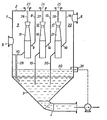
- the drawing shows in schematic form an embodiment of a device according to the invention.
- the container enclosing the device according to the invention consists of a cylindrical, vertically arranged jacket 1, which is closed at the top by a container ceiling 2 and at the bottom by a conically tapering end piece 3.
- the end piece 3 is connected to an outlet line 4 for loaded detergent.
- the cylindrical part of the container also contains a feed nozzle 5 for the gas to be cleaned and a discharge nozzle 6 for cleaned gas.
- a first sub-space 7 is separated by a vertically extending partition plate 8 attached to the container ceiling 2 and an obliquely extending partition plate 9 attached to the lower end of this partition plate and finally by a horizontal partition plate 10 attached to it.
- the separating plates 8, 9 and 10 pass through the container without being curved and are firmly connected to these components at the lines of contact with the cylindrical jacket 1 and the container ceiling 2.
- the oblique dividing plate 9 is pierced by a first venturi washer 11.
- a second subspace 12 adjoining the first subspace 7 is defined by dividing sheets 13 and 14, which correspond to the already described dividing sheets 8 and 9, and a vertically extending dividing sheet 15 adjoining the lower end of the dividing sheet 14.
- the vertical divider ends freely in the lower, tapered end piece 3 of the container.
- the oblique dividing plate 14 is pierced by a second venturi scrubber 16.
- a third sub-space 17 is defined by dividing plates 18, 19 and 20, the obliquely running dividing plate 19 being penetrated by a third venturi washer 21.
- the remaining subspace 22 is delimited by the container wall.
- venturi washers 11, 16 and 21 are supplied with washing liquid from the container ceiling via connections 23, 24 and 25 and lines 26, 27 and 28, respectively. From the lower area of the subspace 7, a line 29 leads from the partition plate 10 into the lower, conical end piece 3 of the container.
- a liquid level 30 is maintained in the lower region of the container, which is above the lower ends of the separating plates 15 and 20, as a result of which the subspaces 12, 17 and 22 for the gas flow are connected to one another.
- the liquid level can be controlled by a control device 31, which controls, for example, the rate of removal of the loaded washing liquid from outlet line 4.
Landscapes
- Chemical & Material Sciences (AREA)
- Chemical Kinetics & Catalysis (AREA)
- Engineering & Computer Science (AREA)
- Analytical Chemistry (AREA)
- General Chemical & Material Sciences (AREA)
- Oil, Petroleum & Natural Gas (AREA)
- Treating Waste Gases (AREA)
- Gas Separation By Absorption (AREA)
Claims (4)
Applications Claiming Priority (2)
| Application Number | Priority Date | Filing Date | Title |
|---|---|---|---|
| DE3046281 | 1980-12-09 | ||
| DE19803046281 DE3046281A1 (de) | 1980-12-09 | 1980-12-09 | Vorrichtung und verfahren zum reinigen eines gasstroms |
Publications (2)
| Publication Number | Publication Date |
|---|---|
| EP0053836A1 EP0053836A1 (fr) | 1982-06-16 |
| EP0053836B1 true EP0053836B1 (fr) | 1984-07-11 |
Family
ID=6118654
Family Applications (1)
| Application Number | Title | Priority Date | Filing Date |
|---|---|---|---|
| EP81110257A Expired EP0053836B1 (fr) | 1980-12-09 | 1981-12-08 | Dispositif et procédé de purification d'un courant gazeux |
Country Status (4)
| Country | Link |
|---|---|
| EP (1) | EP0053836B1 (fr) |
| AU (1) | AU543631B2 (fr) |
| DE (2) | DE3046281A1 (fr) |
| ZA (1) | ZA818538B (fr) |
Families Citing this family (4)
| Publication number | Priority date | Publication date | Assignee | Title |
|---|---|---|---|---|
| DE4314788C1 (de) * | 1993-05-05 | 1994-08-18 | Petersen Hugo Verfahrenstech | Verfahren zur Herstellung einer Venturibaueinheit für einen Venturiwäscher, Venturibaueinheit sowie Verwendung einer Verturibaueinheit in einem Verturiwäscher |
| WO1999013967A1 (fr) * | 1997-09-15 | 1999-03-25 | Den Norske Stats Oljeselskap A.S | Installation de separation de co2 de gaz de combustion de turbine a gaz |
| CN107854945A (zh) * | 2017-12-05 | 2018-03-30 | 中国华电科工集团有限公司 | 一种烟气净化系统 |
| CN108916903B (zh) * | 2018-09-28 | 2024-01-09 | 湖北金炉节能股份有限公司 | 一种烟气混风处理系统 |
Family Cites Families (7)
| Publication number | Priority date | Publication date | Assignee | Title |
|---|---|---|---|---|
| DE1260442B (de) * | 1964-11-12 | 1968-02-08 | Metallgesellschaft Ag | Vorrichtung zum direkten Kuehlen und Waschen von Gasen |
| DE1259297B (de) * | 1964-11-12 | 1968-01-25 | Metallgesellschaft Ag | Vorrichtung zum direkten Kuehlen und Waschen heisser staubhaltiger Gase |
| US4209502A (en) * | 1974-05-06 | 1980-06-24 | Pircon Ladislav J | Heterogeneous process |
| JPS49125977U (fr) * | 1973-02-23 | 1974-10-29 | ||
| AT342632B (de) * | 1973-11-06 | 1978-04-10 | Bischoff Gasreinigung | Gichtgasreinigungsanlage fur druckhochofen |
| FR2382260A1 (fr) * | 1977-03-01 | 1978-09-29 | Air Ind | Installation de lavage de gaz |
| FR2442072A1 (fr) * | 1978-11-21 | 1980-06-20 | Percevaut Emile | Unite de lavage et d'adsorption de gaz polluants ou autres |
-
1980
- 1980-12-09 DE DE19803046281 patent/DE3046281A1/de not_active Withdrawn
-
1981
- 1981-12-08 DE DE8181110257T patent/DE3164773D1/de not_active Expired
- 1981-12-08 EP EP81110257A patent/EP0053836B1/fr not_active Expired
- 1981-12-08 AU AU78351/81A patent/AU543631B2/en not_active Ceased
- 1981-12-09 ZA ZA@@@@00818538A patent/ZA818538B/xx unknown
Also Published As
| Publication number | Publication date |
|---|---|
| DE3046281A1 (de) | 1982-07-08 |
| ZA818538B (en) | 1982-11-24 |
| DE3164773D1 (en) | 1984-08-16 |
| AU7835181A (en) | 1982-06-17 |
| AU543631B2 (en) | 1985-04-26 |
| EP0053836A1 (fr) | 1982-06-16 |
Similar Documents
| Publication | Publication Date | Title |
|---|---|---|
| DE102007050904A1 (de) | Anlage und Verfahren zur Reinigung von Rauchgasen | |
| DE2705903A1 (de) | Horizontale gas-spruehreinigungsvorrichtung | |
| DE2548700A1 (de) | Verfahren und vorrichtung zur gewinnung von wasserstoff und kohlendioxid | |
| DD230788A1 (de) | Adsorbereinheit und verfahren zum betreiben derselben | |
| DE3629947A1 (de) | Vorrichtung zur kontinuierlichen abtrennung von feststoffteilchen aus einer fluessigen suspension | |
| EP0053836B1 (fr) | Dispositif et procédé de purification d'un courant gazeux | |
| DE1924052A1 (de) | Verfahren zum Entfernen von CO2 und/oder H2S aus Spaltgasen und Vorrichtung zum Durchfuehren des Verfahrens | |
| DE4331415C3 (de) | Verfahren und Vorrichtung zur Behandlung eines Gasstromes mit Waschflüssigkeit | |
| DE3634126C2 (fr) | ||
| DE10246540A1 (de) | Reinigungsvorrichtung und Verfahren zur Reinigung von Prozessgas einer Reflowlötanlage | |
| EP0207509B1 (fr) | Procédé et récipient de séparation pour séparer une suspension de lessive et de soufre | |
| EP0029258B1 (fr) | Dispositif de régénération de liquide de lavage et procédé pour son fonctionnement | |
| EP3501622B1 (fr) | Colonne d'absorption et procédé d'épuration de gaz de synthèse brut | |
| DE899036C (de) | Verfahren und Vorrichtung zum Entoelen und/oder Entwaessern von unter Druck stehenden Gasen, Luft oder Daempfen, insbesondere Abdampf | |
| DE2944081A1 (de) | Vorrichtung zur biologischen abwasserreinigung | |
| EP1339469B1 (fr) | Procede et dispositif servant a separer les differentes composantes d'un melange de matieres, par distillation extractive dans une colonne a paroi de separation | |
| DE1407941C3 (de) | Schlauchfilteranlage für Nieder- und Hochdruck-Trockengasreinigung | |
| DE2605287C2 (de) | Verfahren zur Entfernung von sauren Bestandteilen aus Gasen | |
| EP0504498B1 (fr) | Procédé et dispositif de régénération de liquide de lavage de laveur à air | |
| WO2008043444A1 (fr) | Colonne de lavage à hauteur de montage réduite | |
| DE3531416A1 (de) | Gaswaescher | |
| DE4015831C1 (en) | Washing out acid from dust free gas - by washing gas with aq. soln., removing acid formed, subjecting exhaust gas to droplet removal and adding fresh water | |
| EP0571408B1 (fr) | Procede et dispositif pour l'epuration de gaz charges de substances polluantes | |
| DE4030677C2 (fr) | ||
| DE504991C (de) | Vorrichtung zum Auswaschen von Phenolen aus phenolhaltigen Abwaessern |
Legal Events
| Date | Code | Title | Description |
|---|---|---|---|
| PUAI | Public reference made under article 153(3) epc to a published international application that has entered the european phase |
Free format text: ORIGINAL CODE: 0009012 |
|
| AK | Designated contracting states |
Designated state(s): BE DE FR GB IT NL |
|
| 17P | Request for examination filed |
Effective date: 19820505 |
|
| ITF | It: translation for a ep patent filed | ||
| GRAA | (expected) grant |
Free format text: ORIGINAL CODE: 0009210 |
|
| RAP1 | Party data changed (applicant data changed or rights of an application transferred) |
Owner name: PEABODY HOLMES LIMITED Owner name: LINDE AKTIENGESELLSCHAFT |
|
| AK | Designated contracting states |
Designated state(s): BE DE FR GB IT NL |
|
| REF | Corresponds to: |
Ref document number: 3164773 Country of ref document: DE Date of ref document: 19840816 |
|
| ET | Fr: translation filed | ||
| PLBE | No opposition filed within time limit |
Free format text: ORIGINAL CODE: 0009261 |
|
| STAA | Information on the status of an ep patent application or granted ep patent |
Free format text: STATUS: NO OPPOSITION FILED WITHIN TIME LIMIT |
|
| 26N | No opposition filed | ||
| PGFP | Annual fee paid to national office [announced via postgrant information from national office to epo] |
Ref country code: NL Payment date: 19891231 Year of fee payment: 9 |
|
| PGFP | Annual fee paid to national office [announced via postgrant information from national office to epo] |
Ref country code: DE Payment date: 19900122 Year of fee payment: 9 |
|
| ITTA | It: last paid annual fee | ||
| PG25 | Lapsed in a contracting state [announced via postgrant information from national office to epo] |
Ref country code: NL Effective date: 19910701 |
|
| NLV4 | Nl: lapsed or anulled due to non-payment of the annual fee | ||
| PG25 | Lapsed in a contracting state [announced via postgrant information from national office to epo] |
Ref country code: DE Effective date: 19910903 |
|
| PGFP | Annual fee paid to national office [announced via postgrant information from national office to epo] |
Ref country code: GB Payment date: 19911126 Year of fee payment: 11 |
|
| PGFP | Annual fee paid to national office [announced via postgrant information from national office to epo] |
Ref country code: FR Payment date: 19911209 Year of fee payment: 11 |
|
| PGFP | Annual fee paid to national office [announced via postgrant information from national office to epo] |
Ref country code: BE Payment date: 19920204 Year of fee payment: 11 |
|
| PG25 | Lapsed in a contracting state [announced via postgrant information from national office to epo] |
Ref country code: GB Effective date: 19921208 |
|
| PG25 | Lapsed in a contracting state [announced via postgrant information from national office to epo] |
Ref country code: BE Effective date: 19921231 |
|
| BERE | Be: lapsed |
Owner name: PEABODY HOLMES LTD Effective date: 19921231 Owner name: LINDE A.G. Effective date: 19921231 |
|
| GBPC | Gb: european patent ceased through non-payment of renewal fee |
Effective date: 19921208 |
|
| PG25 | Lapsed in a contracting state [announced via postgrant information from national office to epo] |
Ref country code: FR Effective date: 19930831 |
|
| REG | Reference to a national code |
Ref country code: FR Ref legal event code: ST |