EP0053838B1 - Vorrichtung zum Füllen von Schüttgutbehältern - Google Patents
Vorrichtung zum Füllen von Schüttgutbehältern Download PDFInfo
- Publication number
- EP0053838B1 EP0053838B1 EP81110261A EP81110261A EP0053838B1 EP 0053838 B1 EP0053838 B1 EP 0053838B1 EP 81110261 A EP81110261 A EP 81110261A EP 81110261 A EP81110261 A EP 81110261A EP 0053838 B1 EP0053838 B1 EP 0053838B1
- Authority
- EP
- European Patent Office
- Prior art keywords
- rotor
- vanes
- container
- base member
- rotor shaft
- Prior art date
- Legal status (The legal status is an assumption and is not a legal conclusion. Google has not performed a legal analysis and makes no representation as to the accuracy of the status listed.)
- Expired
Links
- 239000013590 bulk material Substances 0.000 title description 19
- 239000000463 material Substances 0.000 claims description 25
- 239000008187 granular material Substances 0.000 description 5
- 230000005484 gravity Effects 0.000 description 5
- 238000000034 method Methods 0.000 description 3
- 239000000428 dust Substances 0.000 description 2
- 239000002245 particle Substances 0.000 description 2
- 239000011347 resin Substances 0.000 description 2
- 229920005989 resin Polymers 0.000 description 2
- 238000005299 abrasion Methods 0.000 description 1
- 230000009286 beneficial effect Effects 0.000 description 1
- 238000010276 construction Methods 0.000 description 1
- 238000007689 inspection Methods 0.000 description 1
- 229920001684 low density polyethylene Polymers 0.000 description 1
- 239000004702 low-density polyethylene Substances 0.000 description 1
- 238000012986 modification Methods 0.000 description 1
- 230000004048 modification Effects 0.000 description 1
- 239000008188 pellet Substances 0.000 description 1
- 239000000843 powder Substances 0.000 description 1
- 230000003014 reinforcing effect Effects 0.000 description 1
- 239000011343 solid material Substances 0.000 description 1
- 238000013022 venting Methods 0.000 description 1
Images
Classifications
-
- B—PERFORMING OPERATIONS; TRANSPORTING
- B65—CONVEYING; PACKING; STORING; HANDLING THIN OR FILAMENTARY MATERIAL
- B65G—TRANSPORT OR STORAGE DEVICES, e.g. CONVEYORS FOR LOADING OR TIPPING, SHOP CONVEYOR SYSTEMS OR PNEUMATIC TUBE CONVEYORS
- B65G69/00—Auxiliary measures taken, or devices used, in connection with loading or unloading
- B65G69/04—Spreading out the materials conveyed over the whole surface to be loaded; Trimming heaps of loose materials
- B65G69/0458—Spreading out the materials conveyed over the whole surface to be loaded; Trimming heaps of loose materials with rotating means, e.g. tables, arms
Definitions
- the present invention relates to an apparatus for filling bulk material containers and, more particularly, to an apparatus for feeding and distributing material within said containers regardless of the configuration of the containers.
- an apparatus for feeding and distributing in a container of varying configuration bulk materials which includes material inlet means positioned near the top of the container; at least partially radially-compartmented rotor means horizontally positioned below the inlet means; and material-deflecting stator means fixedly positioned vertically around the periphery of the rotor means and mounted through means for permitting preselected orientation of the stator means with respect to the rotor means.
- the present invention provides an improvement in the rotor means utilized in the above described apparatus which improvement provides better control, more uniform material distribution and commensurately higher loading than the prior art apparatus.
- the prime object of the present invention is to provide an improvement in apparatus for feeding and distributing bulk materials into containers.
- Another object is to provide an improvement in apparatus for the efficient feeding and distribution of bulk materials into containers without regard to the internal symmetry of the containers.
- the term “container” means relatively large, rigid enclosures, bins or boxes (e.g. silos, hopper cars, van boxes and the like) having either symmetric or asymmetric configurations by shape or volume, relative to the point of filling of such container; and “bulk materials” means the wide range of particle size, shape and density of solid material which may extend from powders, granules, pellets, to small chunks.
- an apparatus for feeding and distributing in a container of varying configuration bulk materials which includes inlet means including a discharge outlet positioned near the top of the container, and rotor means horizontally positioned below said inlet means, said rotor means including a rotor having a substantially circular base member, a rotor shaft for providing movement to said rotor and a system of upright vanes radially distributed on said base member, said vanes extending from the outer periphery of said base member inwardly towards said rotor shaft, whereby said bulk materials are delivered from said inlet means through said discharge outlet into said rotor means characterized in that said base member is detachably secured to said rotor shaft and that said vanes terminate at a point at or prior to the periphery of said discharge outlet of said inlet means to define an unobstructed central area between said rotor shaft and the inward edge of said vanes.
- the unobstructed central area around said rotor is at least co-extensive with the discharge area of the inlet feed means to the rotor.
- the base member preferably includes a central hub which is detachably secured to the rotor shaft.
- the rotor is provided with a cover plate disposed on the upper edges of the vanes characterized by an inner periphery substantially co-extensive with the inner vertical edges of the vanes to define an opening substantially co-extensive with the unobstructed central area in said rotor.
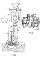
- valve means 14 comprises a manual control valve and valve means 16 a pneumatic, actuated on-off valve.
- the bulk material stream passes through chamber 18 containing mass rate sensor 20 which is electrically connected through line 22 to preset batch counter, integrator and recorder 24 which is, in turn, connected to printer 26.
- An electrical feedback loop is established through line 27 from the integrator 24 to the control of pneumatic valve 16.
- the bulk material stream passes through gravity chute 28 to the material feeding and distribution assembly 30 which is positioned immediately above and within the top of container 32.
- the feeding and distribution assembly 30 comprises an upper chamber 34 through which the bulk material stream passes. Also passing through chamber 34 is rotating shaft 36 driven by motor 38. Positioned on shaft 36 in the chamber 34 is an outwardly-flaring rotating cone 40. A stationary hopper 42 is positioned at the end of gravity chute 28 at approximately the top 44 of container 32. The bulk material stream, feeding under gravity through chute 28 into the system, first encounters a combination of rotating cone 40 and stationary hopper 42 at the end of the chute which is designed to reduce the vertical momentum of the material before feed into the next stages of the system. This combination is also designed to provide uniform feed of material in all azimuthal directions onto the rotor.
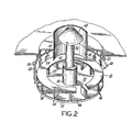
- rotor means 46 of the instant invention is detachably secured to the lower end of shaft 36.
- the rotor means 46 includes a horizontal base 48 which is adapted to be secured at its center to shaft 36 such as by provision of hub 49 which is secured to shaft 36.
- Other means of securement are possible such as a downwardly projecting element (not shown) to be secured to the rotor shaft 36 which would leave the entire surface area of the base 48 free from obstruction from rotor shaft 36 outwardly across the surface of base plate 48 until the edges 53 of the vanes.
- the horizontal base has a substantially circular configuration and is compartmented by a system of upright vanes 50 distributed on the surface of horizontal base 48.
- the vanes extend from the outer periphery 51 of base 48 inwardly toward hub 49 secured to rotor shaft 36 and terminates at a point at or prior to the periphery of discharge outlet 41 of hopper 42 to define an unobstructed central area 52 between hub 49 secured to rotor shaft 36 and the inward edges 53 of vanes 50.
- the number of vanes utilized can range from about 4 to about 12 preferably about eight, and depends among other things on the rotational speed of the rotor and the velocity with which the resin enters the unobstructed area.
- the distance between the inward edges 53 of vanes 50 and the hub 49 secured to rotating shaft 36 can vary depending on the quantity of vanes distributed radially along base 48. In general, however, the vanes should extend about 1/3 the distance between the outer periphery 51 to the hub 49.
- the rotor is optionally provided with a cover plate 55 which as best seen in Fig. 2 is disposed on the upper edges of vanes 50.
- the cover plate has an outer periphery and an inner periphery which is substantially co-extensive with the outer and inner edges of vanes 50 to define an opening substantially co-extensive with central area 52.
- Bulk material is fed to rotor 46 of the distributor means via the center thereof and propelled by centrifugal force away from the rotor.
- the bulk of materials can be processed without employing material-deflecting stator means as disclosed in the above patent.
- a container of unusual design e.g.
- the apparatus disclosed herein can, if desired, include such deflector means.
- bulk material is fed to rotor 46 of the distributor means near the center thereof and propelled by centrifugal force away from the rotor.
- Modification of the direction of propulsion of the bulk material from the rotor is controlled by the positioning of a plurality of stator blades 54 around the periphery of the rotor 46.
- the stator blades 54 are secured to shafts 56 which are, in turn, held by gimbal clamps 58.
- the gimbal clamps 58 are secured to retaining ring 60 which is held through support members 62 to the filling hatch cover or top 44 of container 32.
- Electrical level sensing means 64 are provided above the top 44 of container 32 and is shafted through member 66 to rotating sensor vane member 68 which detects the level of bulk material within the container 32. When the pre-set level is attained sensing means 64 actuates valve 16 through line 70 to stop the stream of bulk material.
- Dust collector means 72 are provided in the top 44 of container 32 and serves to collect dust by the venting of gas therethrough.
- Mode One operates when it is desired to load as much material into the container as possible. When material level reaches the position of the level sensor 68, the sensor will automatically cause the pneumatic valve to close, stopping the loading operation.
- Mode Two provides for the need for a prescribed quantity of material to be loaded into the container. The prescribed amount is programmed into a pre-set batch controller which will then cause the pneumatic valve to close when the integrator unit 24 perceives this desired quantity during the loading operation.
- Example I illustrates a conventional apparatus for loading bulk material into a hopper van.
- Example II illustrates an improvement in loading performance utilizing the improved rotor means of the instant invention without the cover plate
- Example III and IV illustrate the performance of the new rotor at high feed rates
- Example V illustrates the rotors of Examples III and IV including however the cover plate.
- Low density polyethylene granular material of mean particle size 0.0889 cm (0.035 inches) (Range 0.0178 cm (0.007 inches) to 0.254 cm (0.1 inches)) was loaded into a hopper van.
- the hopper van was an essentially rectangular bulk material container with two rectangular hopper sections at the bottom.
- the container measured 2.44 m (8 feet) in width by 6.05 m (19' 10") in length by 2.19 m (7' 2") in height plus the two rectangular hopper sections.
- the overall available volume was 36.25 m 3 (1280 f t3) .
- the gravity chute 28 was 20.32 cm (8 inches) in diameter; the base of the rotating cone 40 was 12.7 cm (5 inches) in diameter; the outlet of the chute hopper 42 was 17.78 cm (7 inches) in diameter; the rotor had 6 vertical dividers which measured 31.75 cm (12 1/2 inches) in diameter having its base inclined outwards and upwards at about 4° to the horizontal; the rotating shaft 36 was 3.81 cm (1 1/2 inches) in diameter; and the hatch opening 44 of the container was 52.07 cm (20 1/2 inches) in diameter.
- a 3,68 Kw (5 HP) motor was employed to drive the rotor at 1750 RPM.
- the bulk material was fed at 16,344 kg (36,000 Ibs)/hr. It was found that, for this set of conditions the container was filled to about 89% of the usable container volume. During this run, under high intensity lights, a large fraction of the material could be seen leaving the rotor at points on the rotor vanes before the outer periphery.
- Example I The apparatus, granular material and operating conditions of Example I was employed except that a new rotor was substituted for the conventional rotor of Example s.
- This rotor was 33.02 cm (13 inches) in diameter with 8 equally spaced vertical dividers extending inward 5.715 cm (2 1/4 inches) from the outer periphery.
- the bulk material was fed at 16,798 kg (37,000 Ibs)/hr.
- the container was filled to 96% of the available volume. Analysis of the rotor performance using a high intensity strobe showed that under these conditions, virtually all the material left the rotor at the outer periphery.
- Example I The apparatus, granular material and operating conditions of.Example I was employed except for the following changes: A new rotor was substituted..This rotor was 33.02 cm (13 inches) in diameter with 8 equally spaced dividers extending inward about 4.76 cm (1 7/8") from the outer periphery. The outlet of the chute hopper was 20.32 cm (8 inches). The bulk material was fed at 24,970 kg (55,000 Ibs)/hr.
- Example III The procedure of Example III was repeated except that the rotor had 12 equally spaced dividers extending inward about 4.76 cm (1 7/8") from the outer periphery of the base member. It was observed that because of the high flow rate and greater quantity of vanes, that a fraction of the resin was being ejected prior to the outer periphery of the vanes with a significant vertical velocity component.
Landscapes
- Engineering & Computer Science (AREA)
- Mechanical Engineering (AREA)
- Filling Or Emptying Of Bunkers, Hoppers, And Tanks (AREA)
- Auxiliary Methods And Devices For Loading And Unloading (AREA)
- Supply Of Fluid Materials To The Packaging Location (AREA)
- Basic Packing Technique (AREA)
Claims (9)
Applications Claiming Priority (2)
| Application Number | Priority Date | Filing Date | Title |
|---|---|---|---|
| US214586 | 1980-12-09 | ||
| US06/214,586 US4342345A (en) | 1980-12-09 | 1980-12-09 | Method and apparatus for filling bulk material containers |
Publications (2)
| Publication Number | Publication Date |
|---|---|
| EP0053838A1 EP0053838A1 (de) | 1982-06-16 |
| EP0053838B1 true EP0053838B1 (de) | 1984-11-28 |
Family
ID=22799655
Family Applications (1)
| Application Number | Title | Priority Date | Filing Date |
|---|---|---|---|
| EP81110261A Expired EP0053838B1 (de) | 1980-12-09 | 1981-12-08 | Vorrichtung zum Füllen von Schüttgutbehältern |
Country Status (5)
| Country | Link |
|---|---|
| US (1) | US4342345A (de) |
| EP (1) | EP0053838B1 (de) |
| JP (1) | JPS57117425A (de) |
| AU (1) | AU547950B2 (de) |
| DE (1) | DE3167509D1 (de) |
Cited By (1)
| Publication number | Priority date | Publication date | Assignee | Title |
|---|---|---|---|---|
| US10016933B2 (en) | 2013-04-23 | 2018-07-10 | Apple Inc. | Rotational assembly method and apparatus |
Families Citing this family (16)
| Publication number | Priority date | Publication date | Assignee | Title |
|---|---|---|---|---|
| FR2582955B1 (fr) * | 1985-06-10 | 1989-10-06 | Tunzini Nessi Entreprise Equip | Dispositif de distribution rotatif pour solides divises |
| FR2620044B1 (fr) * | 1987-09-08 | 1989-12-22 | Pillon Francis | Procede et dispositif pour epandre ou melanger des pulverulents par depot de particules en suspension dans l'air |
| DK161589C (da) * | 1989-04-24 | 1991-12-30 | Rasmussen Th Molle & Maskin | Anordning ved transportbeholdere for risledygtigt massegods |
| US5348434A (en) * | 1992-10-21 | 1994-09-20 | East Coast Terminal Assoc., Ltd. | Cargo loading system |
| FR2721900B1 (fr) * | 1994-06-30 | 1996-08-23 | Inst Francais Du Petrole | Appareillage pour le remplissage d'un recipient avec des particules spheriques |
| DE69627538T2 (de) * | 1996-05-03 | 2004-04-08 | Minnesota Mining And Manufacturing Company, St. Paul | Nichtgewebte schleifmittel |
| WO1997042004A1 (en) * | 1996-05-03 | 1997-11-13 | Minnesota Mining And Manufacturing Company | Method of making a porous abrasive article |
| WO1997042003A1 (en) * | 1996-05-03 | 1997-11-13 | Minnesota Mining And Manufacturing Company | Method and apparatus for manufacturing abrasive articles |
| DE19741601C1 (de) * | 1997-09-20 | 1999-03-04 | Eduard Zink | Vorrichtung zur Ablage von Gegenständen, insbesondere von Kleinteilen, in einen Behälter |
| JP5028075B2 (ja) * | 2006-12-04 | 2012-09-19 | キヤノン株式会社 | 撮像装置及び撮像方法 |
| US20100072308A1 (en) * | 2008-09-19 | 2010-03-25 | William Hemann | Hopper spreader |
| US7762290B2 (en) | 2008-11-06 | 2010-07-27 | Poet Research, Inc. | System for loading particulate matter into a transport container |
| JP2013147266A (ja) * | 2012-01-18 | 2013-08-01 | Ricoh Co Ltd | 粉体充填装置、粉体充填システム、及び粉体充填方法 |
| US9169062B2 (en) * | 2011-06-30 | 2015-10-27 | Kellogg Brown & Root Llc | Lock hopper mass flow arrangement |
| USD814123S1 (en) * | 2017-03-06 | 2018-03-27 | Cixi Haosheng Electronics & Hardware Co., Ltd. | Inverse animal feeder |
| WO2019232312A1 (en) * | 2018-06-01 | 2019-12-05 | The Regents Of The University Of California | System and method for making boron oxide nanoparticles |
Family Cites Families (3)
| Publication number | Priority date | Publication date | Assignee | Title |
|---|---|---|---|---|
| US2956810A (en) * | 1958-03-28 | 1960-10-18 | Voich George | Cinder spreaders |
| JPS525068U (de) * | 1975-06-25 | 1977-01-13 | ||
| US4135560A (en) * | 1976-12-20 | 1979-01-23 | Union Carbide Corporation | Apparatus for filling bulk material containers |
-
1980
- 1980-12-09 US US06/214,586 patent/US4342345A/en not_active Expired - Lifetime
-
1981
- 1981-11-20 AU AU77715/81A patent/AU547950B2/en not_active Ceased
- 1981-11-27 JP JP56189389A patent/JPS57117425A/ja active Pending
- 1981-12-08 DE DE8181110261T patent/DE3167509D1/de not_active Expired
- 1981-12-08 EP EP81110261A patent/EP0053838B1/de not_active Expired
Cited By (1)
| Publication number | Priority date | Publication date | Assignee | Title |
|---|---|---|---|---|
| US10016933B2 (en) | 2013-04-23 | 2018-07-10 | Apple Inc. | Rotational assembly method and apparatus |
Also Published As
| Publication number | Publication date |
|---|---|
| US4342345A (en) | 1982-08-03 |
| AU7771581A (en) | 1982-06-17 |
| EP0053838A1 (de) | 1982-06-16 |
| JPS57117425A (en) | 1982-07-21 |
| DE3167509D1 (en) | 1985-01-10 |
| AU547950B2 (en) | 1985-11-14 |
Similar Documents
| Publication | Publication Date | Title |
|---|---|---|
| EP0053838B1 (de) | Vorrichtung zum Füllen von Schüttgutbehältern | |
| US3178068A (en) | Apparatus for conveying a column of material downward at a uniform rate | |
| US4902185A (en) | Grain spreader | |
| CA1096825A (en) | Volumetric feeder | |
| JP4603688B2 (ja) | ばら粒状材料の高密度化 | |
| US4135560A (en) | Apparatus for filling bulk material containers | |
| KR890002073B1 (ko) | 입상물질 분리기 | |
| CA1110210A (en) | Method and apparatus for low-dust discharge of particulate material through a nozzle | |
| US5593268A (en) | Cargo loading system | |
| US4738403A (en) | Wheel for a vacuum projection grinder | |
| GB2087366A (en) | Apparatus for metering semi-flowable material | |
| US3920116A (en) | Impeller loading device | |
| US4555210A (en) | Spreader device in a storage container for uniform filling of the container with granular storage goods | |
| US3298748A (en) | Apparatus for delivering material to storage containers | |
| US3937522A (en) | Apparatus for continuous feeding of granular material with sharp corners to a conveyer pipe line | |
| US20080264517A1 (en) | Device for Distribution of at Least One Granular Product in a Container Filling Device and Method for Filling Using Such a Device | |
| GB1601568A (en) | Material feed device and plastics recovery installation including such device | |
| US20040265098A1 (en) | Bulk material loading device | |
| DK152338B (da) | Slaglemoelle | |
| US3620390A (en) | Apparatus for spreading particulate material | |
| EP0028115A1 (de) | Zuführvorrichtung und Verfahren zum Zuführen fliessfähigen Materials zu einem Behälter | |
| CN110436217A (zh) | 一种旋转给料机 | |
| EP0062386A1 (de) | Ladevorrichtung | |
| US20050161167A1 (en) | Densifying of a bulk particulate material | |
| CN219566864U (zh) | 一种颗粒物料分料设备 |
Legal Events
| Date | Code | Title | Description |
|---|---|---|---|
| PUAI | Public reference made under article 153(3) epc to a published international application that has entered the european phase |
Free format text: ORIGINAL CODE: 0009012 |
|
| AK | Designated contracting states |
Designated state(s): DE FR GB SE |
|
| 17P | Request for examination filed |
Effective date: 19821104 |
|
| GRAA | (expected) grant |
Free format text: ORIGINAL CODE: 0009210 |
|
| AK | Designated contracting states |
Designated state(s): DE FR GB SE |
|
| PGFP | Annual fee paid to national office [announced via postgrant information from national office to epo] |
Ref country code: FR Payment date: 19841128 Year of fee payment: 4 |
|
| PGFP | Annual fee paid to national office [announced via postgrant information from national office to epo] |
Ref country code: DE Payment date: 19850103 Year of fee payment: 4 |
|
| REF | Corresponds to: |
Ref document number: 3167509 Country of ref document: DE Date of ref document: 19850110 |
|
| ET | Fr: translation filed | ||
| PLBE | No opposition filed within time limit |
Free format text: ORIGINAL CODE: 0009261 |
|
| STAA | Information on the status of an ep patent application or granted ep patent |
Free format text: STATUS: NO OPPOSITION FILED WITHIN TIME LIMIT |
|
| 26N | No opposition filed | ||
| PG25 | Lapsed in a contracting state [announced via postgrant information from national office to epo] |
Ref country code: GB Effective date: 19881208 |
|
| PG25 | Lapsed in a contracting state [announced via postgrant information from national office to epo] |
Ref country code: SE Effective date: 19881209 |
|
| GBPC | Gb: european patent ceased through non-payment of renewal fee | ||
| PG25 | Lapsed in a contracting state [announced via postgrant information from national office to epo] |
Ref country code: FR Free format text: LAPSE BECAUSE OF NON-PAYMENT OF DUE FEES Effective date: 19890831 |
|
| PG25 | Lapsed in a contracting state [announced via postgrant information from national office to epo] |
Ref country code: DE Effective date: 19890901 |
|
| REG | Reference to a national code |
Ref country code: FR Ref legal event code: ST |
|
| EUG | Se: european patent has lapsed |
Ref document number: 81110261.5 Effective date: 19891215 |