EP0053839A1 - Outil à main pour ameublir, couper et grumeler de la terre - Google Patents
Outil à main pour ameublir, couper et grumeler de la terre Download PDFInfo
- Publication number
- EP0053839A1 EP0053839A1 EP19810110267 EP81110267A EP0053839A1 EP 0053839 A1 EP0053839 A1 EP 0053839A1 EP 19810110267 EP19810110267 EP 19810110267 EP 81110267 A EP81110267 A EP 81110267A EP 0053839 A1 EP0053839 A1 EP 0053839A1
- Authority
- EP
- European Patent Office
- Prior art keywords
- bearing
- hand tool
- tool according
- axis
- plastic
- Prior art date
- Legal status (The legal status is an assumption and is not a legal conclusion. Google has not performed a legal analysis and makes no representation as to the accuracy of the status listed.)
- Granted
Links
- 238000005520 cutting process Methods 0.000 title claims abstract description 6
- 239000002689 soil Substances 0.000 title claims abstract description 6
- 229920003023 plastic Polymers 0.000 claims abstract description 20
- 239000004033 plastic Substances 0.000 claims abstract description 20
- 230000001154 acute effect Effects 0.000 claims abstract description 4
- 230000003014 reinforcing effect Effects 0.000 claims description 8
- 229910052751 metal Inorganic materials 0.000 claims description 5
- 239000002184 metal Substances 0.000 claims description 5
- 239000006223 plastic coating Substances 0.000 claims description 3
- 230000015572 biosynthetic process Effects 0.000 claims description 2
- 230000002787 reinforcement Effects 0.000 claims 1
- 125000006850 spacer group Chemical group 0.000 abstract 2
- 239000000463 material Substances 0.000 abstract 1
- 238000010008 shearing Methods 0.000 abstract 1
- 239000004576 sand Substances 0.000 description 4
- 238000004519 manufacturing process Methods 0.000 description 3
- 244000025254 Cannabis sativa Species 0.000 description 2
- 230000007797 corrosion Effects 0.000 description 2
- 238000005260 corrosion Methods 0.000 description 2
- 229910052782 aluminium Inorganic materials 0.000 description 1
- XAGFODPZIPBFFR-UHFFFAOYSA-N aluminium Chemical compound [Al] XAGFODPZIPBFFR-UHFFFAOYSA-N 0.000 description 1
- 238000004140 cleaning Methods 0.000 description 1
- 230000002349 favourable effect Effects 0.000 description 1
- 239000013072 incoming material Substances 0.000 description 1
- 238000002347 injection Methods 0.000 description 1
- 239000007924 injection Substances 0.000 description 1
- 239000007788 liquid Substances 0.000 description 1
- 238000003466 welding Methods 0.000 description 1
Images

Classifications
-
- A—HUMAN NECESSITIES
- A01—AGRICULTURE; FORESTRY; ANIMAL HUSBANDRY; HUNTING; TRAPPING; FISHING
- A01B—SOIL WORKING IN AGRICULTURE OR FORESTRY; PARTS, DETAILS, OR ACCESSORIES OF AGRICULTURAL MACHINES OR IMPLEMENTS, IN GENERAL
- A01B1/00—Hand tools
- A01B1/22—Attaching the blades or the like to handles; Interchangeable or adjustable blades
-
- A—HUMAN NECESSITIES
- A01—AGRICULTURE; FORESTRY; ANIMAL HUSBANDRY; HUNTING; TRAPPING; FISHING
- A01B—SOIL WORKING IN AGRICULTURE OR FORESTRY; PARTS, DETAILS, OR ACCESSORIES OF AGRICULTURAL MACHINES OR IMPLEMENTS, IN GENERAL
- A01B1/00—Hand tools
- A01B1/06—Hoes; Hand cultivators
- A01B1/14—Hoes; Hand cultivators with teeth only
Definitions
- the invention relates to a handheld device for loosening, cutting and crumbling garden soil.
- DE-PS 1 3o3 552 already shows such a hand-held device with freely rotating tine stars arranged on V-shaped bearing axes.
- the radial center planes of these tine stars with in cross section preferably diamond-shaped cross-section with laterally lying cutting edges on each tine, cut at an acute angle, so that the edges of the crossed tines, which slide along one another, form shear points.
- Such a design shows significant advantages with regard to the crushing of lumps and an advantageous self-cleaning due to the scissors-like movement towards one another.
- the object of the invention is to improve these known advantageous handheld devices, in which two tine stars rotate freely on each handle, to the extent that, among other things, the risk of corrosion and the number of stems are reduced, and the position of the tine stars and their interchangeability is improved.
- the bearing sleeves which carry the tine stars are also preferably made of plastic are provided on which the tine stars with inserted slide bearing rings made of self-lubricating plastic or the like can be freely rotated.
- bearing sleeves and the intermediate guide bearings are slidably mounted on the central axis, they can be easily removed from the axis for replacing tine stars or bearing parts and can be opened again. It is preferred according to the invention to clamp the displaceable bearing parts (bearing sleeves, intermediate guide bearings) against one another by means of clamping nuts screwed on the end, so that the bearing parts form a rigid unit on the central axis, which is arranged on a stem.
- the overall assembly of such handheld devices can be carried out quickly and easily in terms of production, so that rational production is provided.
- the invention extends not only to the individual features, but also to their combination.
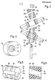
- a central axis 11 On a handle lo a central axis 11 is attached, for example welded, which shows an angular cross section.
- bearing sleeves 12 made of hard plastic are pushed together in a V-shape, arranged in pairs at corresponding angles (acute angles), between which guide bearings 13 made of hard plastic are also connected, the side faces of which are also V-shaped and face each other over the entire surface the bearing sleeves 12 rest.
- the side surfaces of the guide bearings 13 have small gradations.
- the central openings 12a of the bearing sleeves 12 and guide bearings 13 and end bearings 14 are also angular, so that these bearing parts 12, 13, 14 can be displaced in the longitudinal direction of the central axis 11, but not on the latter are rotatably mounted.
- end nuts 15 which are rotatably mounted on end threads 16 of the central axis 11, the aforementioned bearing parts 12, 13, 14 are braced together to form a largely rigid unit.
- the outer side surfaces of the end bearings 14 are each at right angles to the end nuts 15.
- the freely rotatable tine stars 17, for example made of light metal such as aluminum, are each diamond-shaped in cross-section and provided with lateral cutting edges 17a and are supported on the bearing sleeves 12 in such a way that they cross-overlap one another and thereby form advantageous shear points in pairs.
- the shear points lie at adjacent tine stars 17 (see FIG. 2) alternately offset.
- each tine star 17 has a central bore 18 into which a slide bearing ring 19, e.g. made of self-lubricating - the plastic is firmly inserted, which rotates freely on the round outer surface (casing) of the bearing sleeve 12.
- the guide bearings 13 show on their wider outer surface a trough 13b, which is a guide on the one hand forms surface for grass or the like. On the other hand, largely prevents grass or the like from being directly wrapped in the gaps of the guide bearing 13 and bearing 12; this thus counteracts a setting of the tine stars 17.
- the arrangement of the tine stars 17 with their bearings 12 on the central axis 11 gives the handheld device an advantageous rigidity, especially when working on a hardened soil.
- the individual bearing parts 12, 13, 14 and the tine stars 17 can be easily assembled and loosened again, since the end screws 15 make it easier to put the individual parts on and clamp them together and loosen them.
- the bearing parts are secured against rotation, while the tine stars 17 with the bearing sleeves 12 and slide bearing ring 19 slide plastic on plastic.
- the stem 1o which is preferably made of hard plastic, with its grommet 2o has an elongated flat cavity 21 on the axis side in its longitudinal direction, into which a reinforcing plate 22 made of metal is injected, which is provided with central bores 23 for plastic bridge formation.
- the central axis 11 is rigidly connected to this reinforcing plate 23 by welding at the end face. so that handle and axis 11 form an indissoluble unit.
- the manufacture and assembly of the handheld device can For example, so that the reinforcing plate 22 is first welded, screwed or the like in the middle of the central axis 11. Then the plastic coating is injection molded to form a V-shaped intermediate guide bearing 1 0 a both around the central axis 11 and around the reinforcing plate, a spout 2o being formed and the liquid plastic flowing through the holes 23 and there bridges 24 for stiffening and appropriate definition of plastic coating and reinforcing plate 22 forms.
- bearing parts bearing sleeves 12 with attached tine stars 17, intermediate guide bearings 13, end bearings 14
- clamping nuts 15 on the threads 16 (cf. FIG. 3).
- the essential parts of the handheld device are largely made of plastic in order to avoid corrosive metal.
- a round axis 25 is provided, which has a groove 26 which extends over its entire length.
- the respective central opening 12a is formed with a web 27 so that the bearing sleeve 12, the guide bearing 13 and the end bearing 14 with the axis 25 are secured against rotation under tongue and groove connection.
- a web, cam or the like be arranged, in which case corresponding recesses are then formed in the respective central openings 12a and the parts 12, 13, 14 on the rotary axis 25 prevent rotation.
- the outer surface of the bearing sleeve 1-2 is broken by annular collecting channels 28, grooves or the like. in which the sand collects from the friction surface during the rotational movement of the tine stars 17, Verge, Fig. 5 + 6
- annular collecting troughs 28 lead into discharge channels 29 arranged at right angles thereto, which are distributed around the circumference of the bearing sleeves 12.
- discharge channels 29 are arranged. The sand or the like collected in the collecting troughs 28 is led to the outside via the discharge channels 29.
- a bearing sleeve designed in this way thereby reduces the friction of the rotating tines, which has a favorable effect on the function and the service life.
Landscapes
- Life Sciences & Earth Sciences (AREA)
- Engineering & Computer Science (AREA)
- Mechanical Engineering (AREA)
- Soil Sciences (AREA)
- Environmental Sciences (AREA)
- Health & Medical Sciences (AREA)
- Dentistry (AREA)
- Oral & Maxillofacial Surgery (AREA)
- Soil Working Implements (AREA)
- Handcart (AREA)
Priority Applications (1)
| Application Number | Priority Date | Filing Date | Title |
|---|---|---|---|
| AT81110267T ATE15851T1 (de) | 1980-12-10 | 1981-12-09 | Handgeraet zum auflockern, schneiden und kruemeln von gartenboden. |
Applications Claiming Priority (4)
| Application Number | Priority Date | Filing Date | Title |
|---|---|---|---|
| DE3046436 | 1980-12-10 | ||
| DE19803046436 DE3046436A1 (de) | 1980-12-10 | 1980-12-10 | "handgeraet zum auflockern, schneiden und kruemeln von gartenboden" |
| DE8132020U | 1981-11-03 | ||
| DE19818132020 DE8132020U1 (de) | 1981-11-03 | 1981-11-03 | "handgeraet zum auflockern, schneiden und kruemeln von gartenboden" |
Publications (2)
| Publication Number | Publication Date |
|---|---|
| EP0053839A1 true EP0053839A1 (fr) | 1982-06-16 |
| EP0053839B1 EP0053839B1 (fr) | 1985-10-02 |
Family
ID=25789622
Family Applications (1)
| Application Number | Title | Priority Date | Filing Date |
|---|---|---|---|
| EP19810110267 Expired EP0053839B1 (fr) | 1980-12-10 | 1981-12-09 | Outil à main pour ameublir, couper et grumeler de la terre |
Country Status (2)
| Country | Link |
|---|---|
| EP (1) | EP0053839B1 (fr) |
| CA (1) | CA1170891A (fr) |
Cited By (1)
| Publication number | Priority date | Publication date | Assignee | Title |
|---|---|---|---|---|
| EP0150731A3 (en) * | 1984-01-13 | 1986-07-23 | Bielefelder Kuchenmaschinen- Und Transportgeratefabrik Vom Braucke Gmbh | Gardening hand tool for tilling soil |
Families Citing this family (3)
| Publication number | Priority date | Publication date | Assignee | Title |
|---|---|---|---|---|
| EP4326045A4 (fr) | 2021-04-19 | 2025-05-21 | Milwaukee Electric Tool Corporation | Tête de taille-bordure |
| US12582029B2 (en) | 2021-06-30 | 2026-03-24 | Milwaukee Electric Tool Corporation | String trimmer head |
| DE212022000197U1 (de) | 2021-06-30 | 2024-02-19 | Milwaukee Electric Tool Corporation | Fadentrimmeranordung und Trimmerkopf zur Verwendung damit |
Citations (4)
| Publication number | Priority date | Publication date | Assignee | Title |
|---|---|---|---|---|
| FR736952A (fr) * | 1932-05-11 | 1932-12-05 | Instrument aratoire perfectionné | |
| DE7032388U (de) * | 1970-08-31 | 1970-12-03 | Dreyer Heinrich Wilhelm | Bodenbearbeitungsgeraet. |
| DE7822114U1 (de) * | 1978-07-24 | 1978-11-09 | Edenfeld, Heinz, 4543 Lienen | Bodenbearbeitungsgeraet |
| FR2452232A3 (fr) * | 1979-03-29 | 1980-10-24 | Gouvy Et Cie | Procede pour fixer un manche a un outil a soie, et outil a soie s'y rapportant |
-
1981
- 1981-12-04 CA CA000391529A patent/CA1170891A/fr not_active Expired
- 1981-12-09 EP EP19810110267 patent/EP0053839B1/fr not_active Expired
Patent Citations (4)
| Publication number | Priority date | Publication date | Assignee | Title |
|---|---|---|---|---|
| FR736952A (fr) * | 1932-05-11 | 1932-12-05 | Instrument aratoire perfectionné | |
| DE7032388U (de) * | 1970-08-31 | 1970-12-03 | Dreyer Heinrich Wilhelm | Bodenbearbeitungsgeraet. |
| DE7822114U1 (de) * | 1978-07-24 | 1978-11-09 | Edenfeld, Heinz, 4543 Lienen | Bodenbearbeitungsgeraet |
| FR2452232A3 (fr) * | 1979-03-29 | 1980-10-24 | Gouvy Et Cie | Procede pour fixer un manche a un outil a soie, et outil a soie s'y rapportant |
Cited By (1)
| Publication number | Priority date | Publication date | Assignee | Title |
|---|---|---|---|---|
| EP0150731A3 (en) * | 1984-01-13 | 1986-07-23 | Bielefelder Kuchenmaschinen- Und Transportgeratefabrik Vom Braucke Gmbh | Gardening hand tool for tilling soil |
Also Published As
| Publication number | Publication date |
|---|---|
| EP0053839B1 (fr) | 1985-10-02 |
| CA1170891A (fr) | 1984-07-17 |
Similar Documents
| Publication | Publication Date | Title |
|---|---|---|
| DE19928034B4 (de) | Zerkleinerungs- und/oder Siebvorrichtung | |
| DE19857451A1 (de) | Schneid- oder Brechwerkzeug sowie Schneideinsatz für dieses | |
| EP0184209A1 (fr) | Montage pour dent d'excavatrice | |
| EP0150731B1 (fr) | Outil à main de jardinage pour l'ameublissement du sol | |
| DE3402064C2 (de) | Bodenbearbeitungsgerät | |
| EP0053839B1 (fr) | Outil à main pour ameublir, couper et grumeler de la terre | |
| DE3410634C2 (de) | Entzunderungseinheit für eine Entzunderungsvorrichtung | |
| DE10128518A1 (de) | Rotorsystem für Bodenfräse - Minenfräse | |
| EP1860274B1 (fr) | Pointe de forage | |
| EP3669637B1 (fr) | Engin d'abattage-façonnage agricole pourvu de tambour de transport | |
| DE2835634C2 (de) | Maschine zur Bodenbearbeitung | |
| EP2772128B1 (fr) | Fléau et porte-outils correspondant | |
| EP0578051B1 (fr) | Rouleau de compactage à disques dentés | |
| DE3046436C2 (fr) | ||
| DE19703495A1 (de) | Trogmischer, insbesondere Doppelwellen-Trogmischer | |
| DE8132020U1 (de) | "handgeraet zum auflockern, schneiden und kruemeln von gartenboden" | |
| DE3023551C2 (de) | Pflug mit Untergrunddorn | |
| DE29913857U1 (de) | Fräswelle | |
| EP3440921B1 (fr) | Unité d'entraînement pour un convoyeur rotatif, doigt d'entraînement et convoyeur rotatif | |
| AT301231B (de) | Landwirtschaftliches Bodenbearbeitungsgerät | |
| DE20101186U1 (de) | Spargeldammfräsen-Schlegelrotor | |
| DE102005011120B4 (de) | Schneckenbohrer | |
| DE4024772A1 (de) | Zinken fuer dreh-kultivatoren | |
| DE102004027396B3 (de) | Bohrkronenrohr | |
| DE1267457B (de) | Stachelwalze zur Bodenbearbeitung |
Legal Events
| Date | Code | Title | Description |
|---|---|---|---|
| PUAI | Public reference made under article 153(3) epc to a published international application that has entered the european phase |
Free format text: ORIGINAL CODE: 0009012 |
|
| AK | Designated contracting states |
Designated state(s): AT BE CH FR GB IT NL SE |
|
| 17P | Request for examination filed |
Effective date: 19821216 |
|
| ITF | It: translation for a ep patent filed | ||
| GRAA | (expected) grant |
Free format text: ORIGINAL CODE: 0009210 |
|
| AK | Designated contracting states |
Designated state(s): AT BE CH FR GB IT LI NL SE |
|
| REF | Corresponds to: |
Ref document number: 15851 Country of ref document: AT Date of ref document: 19851015 Kind code of ref document: T |
|
| ET | Fr: translation filed | ||
| PLBE | No opposition filed within time limit |
Free format text: ORIGINAL CODE: 0009261 |
|
| STAA | Information on the status of an ep patent application or granted ep patent |
Free format text: STATUS: NO OPPOSITION FILED WITHIN TIME LIMIT |
|
| 26N | No opposition filed | ||
| ITTA | It: last paid annual fee | ||
| PGFP | Annual fee paid to national office [announced via postgrant information from national office to epo] |
Ref country code: SE Payment date: 19941102 Year of fee payment: 14 Ref country code: GB Payment date: 19941102 Year of fee payment: 14 |
|
| PGFP | Annual fee paid to national office [announced via postgrant information from national office to epo] |
Ref country code: FR Payment date: 19941104 Year of fee payment: 14 |
|
| PGFP | Annual fee paid to national office [announced via postgrant information from national office to epo] |
Ref country code: CH Payment date: 19941125 Year of fee payment: 14 |
|
| PGFP | Annual fee paid to national office [announced via postgrant information from national office to epo] |
Ref country code: BE Payment date: 19941130 Year of fee payment: 14 |
|
| PGFP | Annual fee paid to national office [announced via postgrant information from national office to epo] |
Ref country code: AT Payment date: 19941230 Year of fee payment: 14 |
|
| PGFP | Annual fee paid to national office [announced via postgrant information from national office to epo] |
Ref country code: NL Payment date: 19941231 Year of fee payment: 14 |
|
| EAL | Se: european patent in force in sweden |
Ref document number: 81110267.2 |
|
| PG25 | Lapsed in a contracting state [announced via postgrant information from national office to epo] |
Ref country code: GB Effective date: 19951209 Ref country code: AT Effective date: 19951209 |
|
| PG25 | Lapsed in a contracting state [announced via postgrant information from national office to epo] |
Ref country code: SE Effective date: 19951210 |
|
| PG25 | Lapsed in a contracting state [announced via postgrant information from national office to epo] |
Ref country code: LI Effective date: 19951231 Ref country code: CH Effective date: 19951231 Ref country code: BE Effective date: 19951231 |
|
| BERE | Be: lapsed |
Owner name: BIELEFELDER KUCHENMASCHINEN- UND TRANSPORTGERATEF Effective date: 19951231 |
|
| PG25 | Lapsed in a contracting state [announced via postgrant information from national office to epo] |
Ref country code: NL Effective date: 19960701 |
|
| GBPC | Gb: european patent ceased through non-payment of renewal fee |
Effective date: 19951209 |
|
| REG | Reference to a national code |
Ref country code: CH Ref legal event code: PL |
|
| PG25 | Lapsed in a contracting state [announced via postgrant information from national office to epo] |
Ref country code: FR Effective date: 19960830 |
|
| NLV4 | Nl: lapsed or anulled due to non-payment of the annual fee |
Effective date: 19960701 |
|
| REG | Reference to a national code |
Ref country code: FR Ref legal event code: ST |