EP0053872A1 - Federndes Klinken- und Gelenksystem für Verschlüsse - Google Patents
Federndes Klinken- und Gelenksystem für Verschlüsse Download PDFInfo
- Publication number
- EP0053872A1 EP0053872A1 EP81304679A EP81304679A EP0053872A1 EP 0053872 A1 EP0053872 A1 EP 0053872A1 EP 81304679 A EP81304679 A EP 81304679A EP 81304679 A EP81304679 A EP 81304679A EP 0053872 A1 EP0053872 A1 EP 0053872A1
- Authority
- EP
- European Patent Office
- Prior art keywords
- closure
- hinge
- resilient
- closure member
- base member
- Prior art date
- Legal status (The legal status is an assumption and is not a legal conclusion. Google has not performed a legal analysis and makes no representation as to the accuracy of the status listed.)
- Ceased
Links
- 230000002093 peripheral effect Effects 0.000 claims abstract description 12
- 239000000463 material Substances 0.000 claims abstract description 9
- 239000002537 cosmetic Substances 0.000 claims abstract description 8
- 239000000843 powder Substances 0.000 abstract description 4
- 239000004033 plastic Substances 0.000 description 6
- 229920003023 plastic Polymers 0.000 description 6
- 230000006835 compression Effects 0.000 description 4
- 238000007906 compression Methods 0.000 description 4
- JEIPFZHSYJVQDO-UHFFFAOYSA-N iron(III) oxide Inorganic materials O=[Fe]O[Fe]=O JEIPFZHSYJVQDO-UHFFFAOYSA-N 0.000 description 3
- 238000007789 sealing Methods 0.000 description 3
- 238000000034 method Methods 0.000 description 2
- 239000004743 Polypropylene Substances 0.000 description 1
- 239000004676 acrylonitrile butadiene styrene Substances 0.000 description 1
- 210000004905 finger nail Anatomy 0.000 description 1
- 238000012986 modification Methods 0.000 description 1
- 230000004048 modification Effects 0.000 description 1
- 239000004417 polycarbonate Substances 0.000 description 1
- 229920000515 polycarbonate Polymers 0.000 description 1
- -1 polypropylene Polymers 0.000 description 1
- 229920001155 polypropylene Polymers 0.000 description 1
- 239000007787 solid Substances 0.000 description 1
Images


Classifications
-
- A—HUMAN NECESSITIES
- A45—HAND OR TRAVELLING ARTICLES
- A45C—PURSES; LUGGAGE; HAND CARRIED BAGS
- A45C11/00—Receptacles for purposes not provided for in groups A45C1/00-A45C9/00
- A45C11/24—Etuis for purposes not covered by a single one of groups A45C11/02 - A45C11/22, A45C11/26, A45C11/32 - A45C11/38
-
- A—HUMAN NECESSITIES
- A45—HAND OR TRAVELLING ARTICLES
- A45C—PURSES; LUGGAGE; HAND CARRIED BAGS
- A45C13/00—Details; Accessories
- A45C13/10—Arrangement of fasteners
-
- A—HUMAN NECESSITIES
- A45—HAND OR TRAVELLING ARTICLES
- A45C—PURSES; LUGGAGE; HAND CARRIED BAGS
- A45C13/00—Details; Accessories
- A45C13/34—Stays or supports for holding lids or covers open
Definitions
- This invention relates generally to closure members such as the closure members on compacts for cosmetics or other containers and more particularly to a combined spring latch and hinge assembly for pivotally connecting such closure members into operating position which offers a designed resistance to the movement of such closure member from closed to opened position.
- Compacts for powder, rouge and other cosmetics are well known devices and conventional prior art compacts have the closure or cover member pivotally hinged to the base member for movement of the cover member from open to closed position so that they require a conventional interference type clasp unit for sealing the closure or cover member to the base member which interference clasp unit will be located a spaced distance generally opposite from the pivotal hinge means provided on the compact.
- the present invention seeks to provide a unique and improved spring latch and hinge mechanism for compacts or other containers in which designed forces are established to provide a predetermined closed pressure and a designed resistance to closing and to opening of the closure or cover member with respect to the associated base member on which the closure member is pivotally connected, by taking advantage of the inherent strength and thermal plastic memory of the plastic materials from which the compacts are molded.
- the present invention covers an improved spring latch and hinge assembly for a closure means such as the cover member for a container having a base member with a chamber for cosmetics and other purposes including, spaced hinge means having hinge elements respectively on the closure means and the base member to pivotally connect the closure means to said base member, at least one resilient element operatively disposed between the spaced hinge means, and a coacting latch means to exert force on said resilient means and to place the same under compression during movement of the closure means to the closed position to provide a predetermined expansion force to resist opening movement of the latch means.
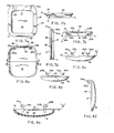
- FIGURES 1 to 8 illustrate the base spring latch and hinge assembly for closure members in accordance with the present invention in which the container is shown in the form of a compact generally designated 10.
- the compact 10 has a base or bottom member 11 and an associated closure or top member 12.
- the base 11 and closure 12 are preferably molded from plastic materials such as polypropylene, acrylonitrile- butadiene-styrene (ABS) and polycarbonate having the strength and thermal plastic memory to provide the improved resilient latch and hinge assembly generally designated 20 for pivotally connecting the closure or top member 12 to the base or bottom member 11 as is more fully described hereinafter.
- plastic materials such as polypropylene, acrylonitrile- butadiene-styrene (ABS) and polycarbonate having the strength and thermal plastic memory to provide the improved resilient latch and hinge assembly generally designated 20 for pivotally connecting the closure or top member 12 to the base or bottom member 11 as is more fully described hereinafter.
- ABS acrylonitrile- butadiene-styrene
- polycarbonate having the strength and thermal plastic memory
- Base or bottom member 11 includes a center section 13 which defines a chamber or receptacle 14 for powder, rouge or the like type of granular cosmetic which receptacle 14 has an open end as at 15 at the upper section of the center section 13.
- Circumferentially disposed and integrally formed about the open end of the center section 13 is an annular flange section 16 which has a substantially flat sealing surface or upper face as at 17 as is shown in FIGURES 3, 7a, 7b, 7c and 7d of the drawings.
- Closure or top member 12 is substantially semispherical to define a cavity 18 which is adapted for various purposes such as the mounting of a mirror, not shown. At the lower end of the top member 12 about the cavity 18 an annular flat rim 19 is formed which will form a seal with the upper surface 17 of the annular flange 16 as will appear clear from the description of the operation of the compact as also set forth below.
- the closure or top member 12 is pivotally connected to and operatively associated with the base or bottom member 11 by means of the improved spring latch and hinge assembly of the present invention so that it can pivot alternatively to an open position to permit access to the opening 15 for the chamber or receptacle 14 and to a closed position when the annular flat rim 19 will coact with the upper face 17 of the annular flange section 16 to seal the opening of the receptacle 14 as will appear clear from the operation of the compact as described below.
- FIGURES 4, 4a, 5, 6a and 6b show that in this form of the invention the improved spring latch and hinge assembly 20 includes snap-in pin type hinges wherein the respective hinge elements are molded as integral parts of the respective base member and closure member.
- hinge supports 21a and 21b having snap-in pin openings as at 22a and 22b extend radially outward and parallel to each other from the central section 13 of the base 11 to the peripheral edge of the annular flange 16 to which these hinge supports 22a and 22b are respectively connected.
- closure member 12 spaced pin supports as at 23a and 23b having pins 24a and 24b thereon extending in opposite directions from each other, are molded so that they lie in the edge of the cavity 18 and in engagement with the annular rim 19 as is clearly shown in FIGURE 8e.
- each of the respective hinge supports 21a and 21b spaced slots 25a and 25b are cut or milled in the annular flange 16 so that they extend radially inward from the peripheral edge of the annular flange 16 just short of the central section 13 so that the innermost portion of the annular flange 16 still remains continuous with the portion thereof which surrounds the opening 15 for the receptacle 14 formed in the central section and the remaining portion lying between the hinge supports 21a and 21b defines a resilient tab or spring leaf member 26 all of which is clearly shown in FIGURES 2, 4, 4a, 6a, 6b, 6c, 7a and 7c of the drawings.
- the downwardly depending pin supports 23a and 23b will be spaced on centers identical with the spacing of the slots 25a and 25b and therefore will fit into these slots so that the pins 24a and 24b can be snapped into the snap-in openings 22a and 22b in the hinge supports 21a and 21b to form the means for pivotally connecting the closure or top member 12 to the base or bottom member 11 so as to permit the arcuate movement thereof relative the base or bottom member as above described.
- FIGURES 1 to 8 of the drawings This is accomplished in the illustrated form of the invention shown in FIGURES 1 to 8 of the drawings by modifying the annular rim at the portion thereof between the depending pin supports 23a and 23b to form a latch section 28 which as shown in FIGURES 4a, 6a, 6b, 8a, 8b and 8e has a curved cove section 29 and a small incremental increase thickness on the edge as at 30 in the latch section 28 which creates a plane at the edge 28 between the depending pin supports that differs from the plane of the annular rim by a predetermined amount generally designated D in the order of .010" which amount can be varied for reasons that will appear clear from the description of the co-action between the edge 28 and the resilient tab or spring latch 26 formed between the slots 25a and 25b in the rear section of the annular flange 16 on the base member 11.
- closure 12 In operation after the closure 12 has the pins 24a and 24b affixed to the snap openings 22a and 22b to pivotally connect the closure 12 to the base 11 as has been above described, it can be rotated about the axis formed by the hinge from the open position to the closed position as shown in FIGURES 6a and 6b. During the course of which movement it will pass through an intermediate position as shown by FIGURE 6b and 6c.
- FIGURES 6a, 6b and 6c it will be noted that as the closure or top member 12 moves from the open to the closed position that the curved cove section 29 of the latch section 28 on the closure member 11 will come into contact with a rounded edge 31 on the spring latch.'26. As the closure member 11 is pivoted further towards the closed position so that it overlies the base 11, the latch section 28 will ride up and over the rounded edge 31. Due to the increased thickness D of the edge 30 on the latch section 28, the latch section 28 will exert an additional force against the spring leaf 26 and will deform or place the spring leaf 26 under stress or compression.
- the force exerted against the front end of the closure 11 must be great enough to establish a moment of force sufficient to overcome the frictional engagement between the curved cove section 29 and the rounded edge 31 and the resilient characteristic of the material from which the spring latch 26 is formed.
- the force exerted against the front end of the closure 11 must be great enough to establish a moment of force sufficient to overcome the frictional engagement between the curved cove section 29 and the rounded edge 31 and the resilient characteristic of the material from which the spring latch 26 is formed.
- By reason of the resiliency of the spring latch 26 it will be deformed and compressed and in the compressed state will act to exert a counter force against the associated edge 30 of the latch 28 on the closure 12 to hold the same in the closed position as shown in FIGURE 6a of the drawings.
- the spring latch and hinge assembly 20 of the form of the invention above described provides various ways in which the resiliency of the spring latch 26 and the forces that are exerted can be adjusted between relatively wide variations for devices of this type. This is desirable in the case of compacts for cosmetics to which the improved spring latch and hinge assembly in accordance with the present invention is particularly applicable.
- the factors which have bearing on this interrelationship of resiliency to force exerted are the coefficient of elasticity of the material from which the container or compact are made and the memory i.e, the ability to return to the former non-compressed state; the radius of curvature of the peripheral end 31 of the spring leaf and the associated radius of curvature of the curved cove section 29 on the latch section 28 of the closure member; the difference between the plane of the rim edge 30 on the latch section of the closure 11 and the plane of the annular rim section 19 thereof; the relative length of the depending pin supports, and the moment of force established by the length of the front section of the closure 11 from the axis of rotation formed by the pin members of the hinge elements.
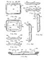
- FIGURES 9 to 15 of the drawings show a cover spring latch and hinge assembly for a container representing an alternate form of the invention.
- the container is also in the form of a compact generally designated 110 molded as stated in the earlier form of the invention from plastic materials having the strength and thermal plastic memory to provide the improved resilient latch and hinge assembly in accordance with the present invention.
- the compact 110 has a base or bottom member 111 and a closure or top member 112 which are operatively and pivotally connected to each other by means of said improved resilient latch and hinge assembly generally designated 120 as is more fully described hereinafter.
- the compact 110 is shown as rectangular in plan view. It is again noted that while the compact is illustrated as rectangular in plan view that those skilled in the art will understand that the shape and size of the particular container which utilizes the improved resilient latch and hinge assembly in accordance w:.th the present invention will be in accordance with the commercial requirements for devices of this type.
- Base or bottom member 111 includes a center section 113 which defines a receptacle 114 having an opening 115 about the upper end of the center section 113.
- the upper end of the central section 113 has a beveled sealing surface as at 116 and at the front end a stop shoulder 117 is formed to coact with the closure member 112 as is shown at FIGURES 11, 13, 14a and 14b of the drawings.
- closure or top member 112 is rectangular in plan view it forms a semi-cylindrical cavity 118 for various purposes and about the cavity 118 has an annular rim section as at 119 which is modified at the back or rear end to permit the closure or top member 112 to be pivotally connected to and operatively associated with the base or bottom member 111 by means of the improved spring latch and hinge assembly 120 so that it can pivot alternatively to an open position to permit access to the opening 115 for the chamber or receptacle 114 and to a closed position wherein a beveled face as at 119a between the cavity 118 and the annular rim 119 is provided to coact with the beveled upper surface 116 of the base or bottom member 111 to maintain the opening 115 substantially closed in the closed position as is clear from FIGURE 14a of the drawings.
- front end at 119b forms an L-shaped groove which is adapted to engage the stop shoulder 117 on the corresponding associated front edge of the base or bottom member 111 as is also shown in FIGURES 14a and 14b of the drawings.
- FIGURES 1, 2, 3 and 14a to 16c inclusive show that in this form of the invention the improved spring latch and hinge assembly 120 includes shaft type hinges wherein the respective hinge elements are molded as integral parts of the respective base member 111 and closure member 1-12 so they can be connected to rotate on the associated hinge shaft pins at 121a and 121b.
- inboard hinge members are formed as at 122a and 122b with aligned hinge pin shaft openings extending therethrough as at 123a and 123b.
- a sized and solid boss 124 is formed continuous and integral with the associated rear end lllr of the base or bottom member 111, the boss 124 being so fixed that it is not resilient for reasons that will appear clear when the operation of this form of the invention is described.
- boss 124 is rounded at its outer peripheral edge as at 125 and its upper face has a raised flat section as at 126 positioned or disposed a predetermined spaced distance "d" above the peripheral surface 127 of the rim 119 on the upper end of the central section 113 of the base or bottom member 111.
- FIGURES 1, 3, 14a, b and c and FIGURE 16a of the drawings Spaced outwardly of the inboard hinges 122a and 122b are spaced recesses as at 128a and 128b all of which is shown in FIGURES 1, 3, 14a, b and c and FIGURE 16a of the drawings.
- the spaced coacting outboard hinge members 129a and 129b are formed on centers which correspond to the respective centers of the based recesses 128a and 128b.
- the spaced outboard hinged members 129a and 129b depend downwardly from the rear end section 112r of the annular rim 119 and are molded and formed continuous therewith and are provided with aligned hinge pin shaft openings as at 130a and 130b so that when the hinge members 129a and 129b are aligned and fitted into the spaced recesses 128a and 128b hinge pins 121a and 121b can be pressed through the respective lined hinge pins shaft opening at 122a and 130a for one set of hinge elements and 122b and 130b for the other set of hinge elements as is shown in FIGURES 10, 14a, 16b and 14b of the drawings.
- FIGURES 9 to 16 of the drawings This however is accomplished in the form of the invention illustrated at FIGURES 9 to 16 of the drawings by modifying the rear section 112r of the closure member between the outboard hinge members 129a and 129b so that the same is resilient and by providing it with a curved cove section as at 131 so that as this modified rear section 112r of the closure 112 is pivoted from the open position shown in phantomized dashed and dotted lines in FIGURES 14b through the intermediate position also shown in FIGURE 14b in phantomized dashed lines, the curved cove section 131 will engage the rounded edge 125 of the boss 124.
- the rear section 112r will be brought into frictional engagement with the portion of the rounded section 125 and the raised flat section 126 on the boss 124 and in order to overcome the frictional engagement manual force will be exerted on the front end of the closure or top member 112 until the resilient rear section 112r bows or compresses sufficiently to permit the closure member 112 to move over the raised flat section 126 to the closed position where the rear section 112r of the closure member will then engage the flat surface 126 on the boss 124.
- the spring latch and hinge assembly 120 of this form of the invention provides various ways in which the resiliency of the spring latch formed by the cover and boss and the forces that are exerted can be adjusted between these elements. More particularly the strength of the boss, the relevant resiliency of the cover 112 and the relationship between the clearances of the upper face of the boss and curvature of the rounded peripheral edge and the curved cove section are factors which can be taken into account for the desired adjustment of this form of the invention.
Landscapes
- Closures For Containers (AREA)
Applications Claiming Priority (2)
| Application Number | Priority Date | Filing Date | Title |
|---|---|---|---|
| US211216 | 1980-11-28 | ||
| US06/211,216 US4345607A (en) | 1980-11-28 | 1980-11-28 | Spring latch and hinge assembly for closure members |
Publications (1)
| Publication Number | Publication Date |
|---|---|
| EP0053872A1 true EP0053872A1 (de) | 1982-06-16 |
Family
ID=22786001
Family Applications (1)
| Application Number | Title | Priority Date | Filing Date |
|---|---|---|---|
| EP81304679A Ceased EP0053872A1 (de) | 1980-11-28 | 1981-10-08 | Federndes Klinken- und Gelenksystem für Verschlüsse |
Country Status (5)
| Country | Link |
|---|---|
| US (1) | US4345607A (de) |
| EP (1) | EP0053872A1 (de) |
| JP (1) | JPS5796958A (de) |
| CA (1) | CA1150679A (de) |
| PT (1) | PT74031B (de) |
Cited By (5)
| Publication number | Priority date | Publication date | Assignee | Title |
|---|---|---|---|---|
| EP0135979A3 (de) * | 1983-09-21 | 1986-07-23 | Corona Plastics, Inc. | Puderdose mit hermetischem Verschluss |
| EP0570299A1 (de) * | 1992-05-15 | 1993-11-18 | Société dite: LIR FRANCE(S.A.) | Gehäuse mit einem Klappdeckel der ständig in eine offene Position zurückgestellt wird |
| FR2691134A1 (fr) * | 1992-05-15 | 1993-11-19 | Lir France Sa | Boîtier à couvercle articulé rappelé en position d'ouverture. |
| USRE46854E1 (en) | 2011-11-02 | 2018-05-22 | Kr. Co., Ltd. | Airtight cosmetic container |
| EP3542666A4 (de) * | 2016-11-17 | 2020-06-17 | Yonwoo Co.,Ltd | Rotierender offener und geschlossener kosmetikbehälter |
Families Citing this family (42)
| Publication number | Priority date | Publication date | Assignee | Title |
|---|---|---|---|---|
| JPS5832711U (ja) * | 1981-08-24 | 1983-03-03 | 吉田工業株式会社 | コンパクト容器 |
| JPS5910704U (ja) * | 1982-07-13 | 1984-01-23 | 株式会社小林コ−セ− | コンパクト |
| JPS5975202U (ja) * | 1982-11-12 | 1984-05-22 | 吉田工業株式会社 | コンパクト容器 |
| USD283853S (en) | 1983-10-05 | 1986-05-20 | Clairol Incorporated | Lighted mirror |
| USD285414S (en) | 1984-06-06 | 1986-09-02 | Scott Paper Company | Packaging container |
| US4917131A (en) * | 1985-05-06 | 1990-04-17 | Contreras Sr Joseph P | Latch assembly and front release mechanism for compacts and other containers |
| US5176463A (en) * | 1987-07-30 | 1993-01-05 | Trw United-Carr Gmbh & Co. | Joint connection between two plastic parts |
| US4962551A (en) * | 1989-03-20 | 1990-10-16 | Invacare Corporation | Portable commode |
| JPH0688702B2 (ja) * | 1990-04-19 | 1994-11-09 | 東海興業株式会社 | 紙送り装置 |
| US5551197A (en) | 1993-09-30 | 1996-09-03 | Donnelly Corporation | Flush-mounted articulated/hinged window assembly |
| US7838115B2 (en) | 1995-04-11 | 2010-11-23 | Magna Mirrors Of America, Inc. | Method for manufacturing an articulatable vehicular window assembly |
| US5793016A (en) * | 1997-01-10 | 1998-08-11 | Illinois Tool Works Inc. | Remote foot control for TIG welding |
| US6283298B1 (en) | 1998-11-25 | 2001-09-04 | Concept Workshop Worldwide, Llc | Airtight container and method for filling container with product |
| US6326592B1 (en) | 2000-08-25 | 2001-12-04 | Illinois Tool Works Inc. | Base for foot control |
| USD482498S1 (en) | 2001-10-10 | 2003-11-18 | Taesung Inc. Co., Ltd. | Lip palette |
| FR2858301B1 (fr) * | 2003-07-29 | 2006-05-26 | Airsec | Conteneur dessicatif etanche pour le conditionnement de produits sensibles a l'humidite ambiante |
| FR2863968B1 (fr) * | 2003-12-19 | 2007-03-02 | Airsec | Dispositif pour l'obturation etanche et le traitement de purification de l'air ambiant de conteneurs de conditionnement pour des produits sensibles a des agents polluants |
| GB2418209C (en) * | 2004-09-15 | 2008-02-12 | Jeffrey Allen | A toilet seat assembly |
| US9237791B2 (en) * | 2006-09-29 | 2016-01-19 | Mark Kay Inc. | Cosmetic container |
| USD555288S1 (en) | 2006-09-29 | 2007-11-13 | Mary Kay Inc. | Cosmetic container |
| EP2207727B1 (de) * | 2007-11-16 | 2016-05-11 | Clariant Production (France) S.A.S. | Behälter |
| USD602015S1 (en) * | 2008-04-07 | 2009-10-13 | Apple Inc. | Electronic device |
| USD615083S1 (en) | 2008-04-07 | 2010-05-04 | Apple Inc. | Electronic device |
| USD1033379S1 (en) | 2008-04-07 | 2024-07-02 | Apple Inc. | Electronic device |
| USD602016S1 (en) | 2008-04-07 | 2009-10-13 | Apple Inc. | Electronic device |
| US8180410B2 (en) * | 2008-06-06 | 2012-05-15 | Sandisk Technologies Inc. | Housing and clip assembly for portable electronics device |
| US8047363B2 (en) * | 2008-08-26 | 2011-11-01 | Sandisk Technologies Inc. | Memory card holder and organizer for holding and organizing a plurality of portable memory cards |
| USD592667S1 (en) * | 2008-08-26 | 2009-05-19 | Sandisk Corporation | Memory card holder |
| USD593561S1 (en) * | 2008-08-26 | 2009-06-02 | Sandisk Corporation | Memory card holder |
| USD613293S1 (en) | 2008-08-26 | 2010-04-06 | Sandisk Corporation | Memory card holder |
| EP2842886B1 (de) * | 2008-10-24 | 2018-09-26 | Clariant Healthcare Packaging (France) S.A.S. | Schraubverschluss, Behälterkörper und Behälter |
| USD613744S1 (en) * | 2009-06-02 | 2010-04-13 | Sandisk Corporation | Memory card holder |
| WO2011030176A1 (en) | 2009-09-09 | 2011-03-17 | Sandisk Il Ltd. | Holders for portable memory cards and method for manufacturing same |
| WO2015126381A1 (en) * | 2014-02-19 | 2015-08-27 | Aptargroup, Inc. | Applicator having a lid usable as a handle |
| EP3100634B1 (de) * | 2014-03-07 | 2019-06-19 | Pum-Tech Korea Co., Ltd | Kosmetikbehälter mit innenbehälter und dichtungsanordnung für innenbehälterkappe |
| TWI508653B (zh) * | 2014-06-10 | 2015-11-11 | Wistron Corp | 抽換式導流機構及其電子裝置 |
| KR200486058Y1 (ko) * | 2015-01-02 | 2018-03-28 | 씨제이제일제당 (주) | 다중 걸림구조를 가진 용기용 마개 |
| WO2017078192A1 (ko) * | 2015-11-04 | 2017-05-11 | 펌텍코리아 (주) | 버튼이 일체로 형성된 콤팩트 용기 |
| USD859746S1 (en) * | 2016-05-06 | 2019-09-10 | Container Limited | Compact |
| USD825110S1 (en) * | 2016-05-31 | 2018-08-07 | KIKO S.p.A. | Cosmetic product |
| USD835350S1 (en) * | 2017-02-16 | 2018-12-04 | Elc Management Llc | Cosmetic compact |
| USD845551S1 (en) | 2017-02-16 | 2019-04-09 | Elc Management Llc | Cosmetic compact |
Citations (3)
| Publication number | Priority date | Publication date | Assignee | Title |
|---|---|---|---|---|
| US1494165A (en) * | 1922-07-12 | 1924-05-13 | Robert S Hall | Radiator or other cap |
| US2637460A (en) * | 1951-05-02 | 1953-05-05 | Tri State Plastic Molding Co | Container having a hinged cover |
| GB780228A (en) * | 1954-07-21 | 1957-07-31 | Hofmann Ulrich | Improvements in or relating to hinged lids or flaps under spring action |
Family Cites Families (2)
| Publication number | Priority date | Publication date | Assignee | Title |
|---|---|---|---|---|
| US1950465A (en) * | 1933-05-12 | 1934-03-13 | Norton Lab | Hinged receptacle |
| US3776245A (en) * | 1972-03-22 | 1973-12-04 | Vca Corp | Molded plastic compact with mirror member |
-
1980
- 1980-11-28 US US06/211,216 patent/US4345607A/en not_active Expired - Lifetime
-
1981
- 1981-06-11 CA CA000379571A patent/CA1150679A/en not_active Expired
- 1981-10-05 JP JP56157618A patent/JPS5796958A/ja active Pending
- 1981-10-08 EP EP81304679A patent/EP0053872A1/de not_active Ceased
- 1981-11-24 PT PT74031A patent/PT74031B/pt unknown
Patent Citations (3)
| Publication number | Priority date | Publication date | Assignee | Title |
|---|---|---|---|---|
| US1494165A (en) * | 1922-07-12 | 1924-05-13 | Robert S Hall | Radiator or other cap |
| US2637460A (en) * | 1951-05-02 | 1953-05-05 | Tri State Plastic Molding Co | Container having a hinged cover |
| GB780228A (en) * | 1954-07-21 | 1957-07-31 | Hofmann Ulrich | Improvements in or relating to hinged lids or flaps under spring action |
Cited By (6)
| Publication number | Priority date | Publication date | Assignee | Title |
|---|---|---|---|---|
| EP0135979A3 (de) * | 1983-09-21 | 1986-07-23 | Corona Plastics, Inc. | Puderdose mit hermetischem Verschluss |
| EP0570299A1 (de) * | 1992-05-15 | 1993-11-18 | Société dite: LIR FRANCE(S.A.) | Gehäuse mit einem Klappdeckel der ständig in eine offene Position zurückgestellt wird |
| FR2691134A1 (fr) * | 1992-05-15 | 1993-11-19 | Lir France Sa | Boîtier à couvercle articulé rappelé en position d'ouverture. |
| US5344037A (en) * | 1992-05-15 | 1994-09-06 | Lir France | Case with articulated cover urged to open position |
| USRE46854E1 (en) | 2011-11-02 | 2018-05-22 | Kr. Co., Ltd. | Airtight cosmetic container |
| EP3542666A4 (de) * | 2016-11-17 | 2020-06-17 | Yonwoo Co.,Ltd | Rotierender offener und geschlossener kosmetikbehälter |
Also Published As
| Publication number | Publication date |
|---|---|
| PT74031B (en) | 1986-01-13 |
| JPS5796958A (en) | 1982-06-16 |
| PT74031A (en) | 1981-12-01 |
| US4345607A (en) | 1982-08-24 |
| CA1150679A (en) | 1983-07-26 |
Similar Documents
| Publication | Publication Date | Title |
|---|---|---|
| US4345607A (en) | Spring latch and hinge assembly for closure members | |
| US4693392A (en) | Hinge, and boss assembly for closure members | |
| US4454889A (en) | Compact with air tight closure | |
| US4917131A (en) | Latch assembly and front release mechanism for compacts and other containers | |
| AU2002335934B2 (en) | Container lid | |
| JPS62683B2 (de) | ||
| EP0720950A1 (de) | Deckelöffnungsmechanismus | |
| GB2053164A (en) | Lid structures | |
| AU2002335934A1 (en) | Container lid | |
| AU6472698A (en) | Metal container having resilient hinged connector | |
| JP2000296018A (ja) | 単一ピース型関節結合アセンブリ | |
| JP3519781B2 (ja) | 気密化粧料容器 | |
| US4477941A (en) | Spring loaded luggage case hinge | |
| JPH0937839A (ja) | 気密化粧料容器 | |
| US5787906A (en) | Deformable push-button release for cosmetic compacts | |
| WO2003000566A1 (en) | Container lid | |
| WO1995033392A1 (en) | Hinged package having an adjustable cover | |
| JP3405368B2 (ja) | 気密化粧料容器 | |
| JPS6025930Y2 (ja) | 化粧用コンパクト | |
| JPH0344083Y2 (de) | ||
| JPS6026728Y2 (ja) | コンパクト容器 | |
| JP2583882Y2 (ja) | ふた付き容器 | |
| JPH081691Y2 (ja) | コンパクトケースの蝶番機構 | |
| JPH0725134Y2 (ja) | コンパクト容器 | |
| JPH07238908A (ja) | 係止構造 |
Legal Events
| Date | Code | Title | Description |
|---|---|---|---|
| PUAI | Public reference made under article 153(3) epc to a published international application that has entered the european phase |
Free format text: ORIGINAL CODE: 0009012 |
|
| AK | Designated contracting states |
Designated state(s): AT BE CH DE FR GB IT LI SE |
|
| 17P | Request for examination filed |
Effective date: 19821211 |
|
| STAA | Information on the status of an ep patent application or granted ep patent |
Free format text: STATUS: THE APPLICATION HAS BEEN REFUSED |
|
| 18R | Application refused |
Effective date: 19861024 |
|
| RIN1 | Information on inventor provided before grant (corrected) |
Inventor name: SASS, GEORGE J. Inventor name: CONTRERAS, JOSEPH P. |