EP0053887A1 - Tête d'impression pour imprimante par points - Google Patents
Tête d'impression pour imprimante par points Download PDFInfo
- Publication number
- EP0053887A1 EP0053887A1 EP81305511A EP81305511A EP0053887A1 EP 0053887 A1 EP0053887 A1 EP 0053887A1 EP 81305511 A EP81305511 A EP 81305511A EP 81305511 A EP81305511 A EP 81305511A EP 0053887 A1 EP0053887 A1 EP 0053887A1
- Authority
- EP
- European Patent Office
- Prior art keywords
- needle
- spring
- spring support
- printing head
- armature
- Prior art date
- Legal status (The legal status is an assumption and is not a legal conclusion. Google has not performed a legal analysis and makes no representation as to the accuracy of the status listed.)
- Granted
Links
Images


Classifications
-
- B—PERFORMING OPERATIONS; TRANSPORTING
- B41—PRINTING; LINING MACHINES; TYPEWRITERS; STAMPS
- B41J—TYPEWRITERS; SELECTIVE PRINTING MECHANISMS, i.e. MECHANISMS PRINTING OTHERWISE THAN FROM A FORME; CORRECTION OF TYPOGRAPHICAL ERRORS
- B41J2/00—Typewriters or selective printing mechanisms characterised by the printing or marking process for which they are designed
- B41J2/22—Typewriters or selective printing mechanisms characterised by the printing or marking process for which they are designed characterised by selective application of impact or pressure on a printing material or impression-transfer material
- B41J2/23—Typewriters or selective printing mechanisms characterised by the printing or marking process for which they are designed characterised by selective application of impact or pressure on a printing material or impression-transfer material using print wires
- B41J2/235—Print head assemblies
- B41J2/265—Guides for print wires
Definitions
- the present invention relates to dot printers and more particularly to a printing head of a dot printer.
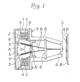
- Fig. 1 shows a conventional example.
- numeral 1 designates a support member provided with a plurality of electromagnets 2.
- Each electromagnet 2 comprises a coil 4 mounted on a yoke 3 and an armature 5 rotatably mounted thereon.
- On the support member 1 is mounted a cover 7 to which a stopper 6 is supported to determine the reset position of the armature 5.
- a guide holder 8 is attached to the support member 1 using screws 9.
- In the front surface and the center of the guide holder.8 are fixed needle guides 11, 12 which align a plurality of needles 10 and hold them slidable, and in the rear portion thereof is fixed a plate-shaped spring support 14 which allows the needles pass through and receives one end of needle springs 13 with coil spring. Other end of each needle spring 13 is contacted with a cap 15 fixed to the rear end of the needle 10.
- a platen 18 is installed on the front surface,of the needle guide 11 and holds a paper 17 opposite to a printing ribbon 16. A specific needle is slided by means of attracting action of the armature 5, thus printing is performed.
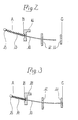
- the needle 10 slides by force of the needle spring 13 so that the top end of the needle 10 goes back from position C of the needle guide 11 and the rear end further projects backwards from attraction position A of the armature 5, as shown in Fig. 2. It is therefore impossible that all needles 10 pass through the needle guide 11 and all armatures 5 are held at pushing state to mount the stopper 6. Accordingly, the armatures 5 must be temporarily fixed one at a time so as to insert the needles 10 in the needle guide 11 and then released from the temporary fixing state after mounting the stopper 6, resulting in quite troublesome work. If one stopper 6 determines the reset position of one armature 5 only, the temporary fixing work of the armature 5 may be omitted.
- An object of this invention is to facilitate the assembling work of printing head.
- Another object of this invention is to enable the secure printing even if distance between the printing head and the platen is large and to prevent the paper from being made dirty by the printing ribbon.
- a still another object of this invention is to enable the needle to be driven by the electromagnet of small capacity.
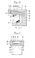
- a needle 10 is held slidable, and a disk-shaped spring support 20 which supports one end of a needle spring 13 is held slidable in longitudinal direction by a guide holder 8.
- the guide holder 8 is provided with an annular groove 22 which engages a stop ring 21 to fix the spring support 20 at rear position B.
- the spring support 20 is advanced towards the platen 18 as shown in Fig. 5.
- the spring support 20 is in advanced position B', the top end of the needle 10 is not pulled out of the needle guide 11, and the rear end is disposed in front of the attraction position ' A of the armature 5.
- the assembling work of the armature 5 and the stopper can be carried out easily when the needle 10 is not inserted in the needle guide 11 and without influence of the needle spring 13.
- a unit is constituted by assembling the electromagnet 2, the stopper 6 and the cover 7 on the support member 1 and the guide holder 8 which moves the spring support 20 in the advanced position B' is connected to the unit using the screws 9.
- a spring support 24 provided with an engaging pawl 23 having elasticity is installed, and engaging recesses 25, 26 to be engaged with the engaging pawl 23 are formed on the guide holder 8.
- the spring support 24 is advanced and the engaging pawl 23 is engaged with the recess 25 under spring action.
- the engaging pawl 23 is engaged with the engaging recess 26 and the contact force of the needle 10 to the armature 5 is determined.
- Coil spring used as the needle spring 13 may be tension spring, or the needle spring of leaf spring may be used.
- this invention is constituted as above described, the assembling work of the armature and the stopper can be- carried out when the spring support is moved forwards and without influence of the needle spring.
- this invention has such effects that the needle spring having small spring constant can be used, distance between the top end of the needle and the platen may be widened, the paper is prevented from being made dirty by the printing ribbon, and the electromagnet of small capacity can drive the needle so as to save electric power.
- armature mounting structure On the support member 1 is fixedly mounted the guide frame 8 which holds a plurality of needles 10 slidable.
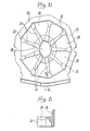
- the support member 1 encloses the yoke 3 with a plurality of electromagnets 2 installed in annular arrangement, and a support 28 is disposed on an attraction surface 27 of the yoke 3.
- the support 28 is provided with a guide recess 29 which holds the armature 5 opposite to the attraction surface 27 and rotatable, and the center of the support 28 is provided with a polygonal hole 30 which holds the stopper 6 slidable.
- the guide recess 29 is divided by a plurality of ribs 31 arranged radially.
- a pedestal 32 contacting to outer portion of the attraction surface 27 of the yoke 3 is formed on outer portion of each rib 31, and the outer end of the rib 31 is connected to an annular rib 33 for reinforcement.
- Outer surface of the support 28 is made a base surface 34 to set the end surface of the stopper 6, and the cover 7 provided with a flat surface 35 contacting to the base surface 34 is mounted on a peripheral wall 37 of the support member 1 spaced with each other by a gap 38.
- An armature spring 39 for urging the armature 5 in the reset direction is provided with a plurality of foot portions 40, each contacting to outer portion of the armature 5 in the guide recess 29 of the support 28.
- the center to which the foot portions 40 join is opened in order to open one surface of the stopper 6.
- the support 28 also supports a thin mica (not shown) interposed between the attraction surface 27 and the armature 5.
- the armature 5 is rotated about fulcrum i.e. outer portion of the attraction surface 27 of the yoke 3 which projects from inner side of the annular rib.
- the needle 10 is slided for the printing action, and the armature 5 is reset by the armature spring 39 and also the needle 10 is reset by the needle spring 13.
- the base surface 34 of the support 28 is pushed by the flat surface 35 of the cover 7, thereby the support 28 is brought into close contact with the attraction surface 27.
- the stopper 6 is grasped between the extension surface of the flat surface 28 of the cover 7 and the armature 5, thereby one end of the stopper 6 coincides with the base surface 34.
- stroke of the armature 5 is determined based on dimension of distance between the attraction surface 27 and the base surface 34 subtracted by thickness of the stopper 6 and the armature 5.
- variation of distance between the attraction surface 27 and the base surface 34 to set the stopper 6 is determined by dimension accuracy in one portion of one component therefore factors for variation are quite small.
- a single product of the stopper 6 and the armature 5 can be easily finished with plate thickness in small tolerance.
- the support 28 may be used only by grinding the base surface 34. Stroke of the armature 5 therefore can be determined accurately. Since the guide recess 29 is formed on the support 28, component to guide rotation of the armature 5 and component to locate the stopper 6 may be commonly constituted thereby the number of components can be decreased.
- the bottom of the support member 1 receives the yoke 3, the armature 5 and the armature spring 39 as well as the support 28 to support the stopper 6 contacted in order, and then the cover 7 may be fixed to the support member 1 so as to facilitate the assembling work.
- the stopper 6 is held at the center of_ the support 28 therefore the outer diameter can be reduced. Reduction of the outer diameter enables the ring connecting the rear end of the needle 10 to be reduced and the needle 10 to be led to the needle guide 11 at the top end without bending the needle 10 so much. Accordingly, the needle-10 can be slided smoothly. Furthermore capacity of the electromagnet coil 4 may'be reduced so as to save electric power.
- the support 28 is provided with the support hole 30 to hold the stopper 6 slidable, it is possible that the stopper 6 is slided and position of the stopper 6 relative to the attraction surface 27 is determined by jig and the stopper 6 is fixed to the determined position by means of adhesive agent.
- this embodiment is constituted as above described, dimension between the attraction surface of the yoke and the stopper mounting surface can be made within small tolerance by finishing dimension at one portion of one component di.sposed between the mounting surface of the support to the attraction surface and the base surface within tolerance. Accordingly, variation of stroke of the armature caused by integration of tolerance can be prevented, and the assembling work can be simplified. Furthermore the flat surface of the cover is contacted with the base surface of the support, thereby the support is brought into close contact with the attraction surface of the yoke. If the stopper is grasped between the extension surface of the flat surface of the cover contacting to the base surface and the armature, the base surface can be easily set by only grinding one surface of the support. When the support guides rotation of the armature, component to locate the stopper and component to guide operation of the armature can be commonly constituted so as to reduce the number of components and further improve productivity of the assembling work.
Landscapes
- Impact Printers (AREA)
Priority Applications (1)
| Application Number | Priority Date | Filing Date | Title |
|---|---|---|---|
| AT81305511T ATE7873T1 (de) | 1980-12-05 | 1981-11-23 | Drahtmatrixdruckkopf. |
Applications Claiming Priority (4)
| Application Number | Priority Date | Filing Date | Title |
|---|---|---|---|
| JP17185280A JPS5795481A (en) | 1980-12-05 | 1980-12-05 | Printing head for dot printer |
| JP171852/80 | 1980-12-05 | ||
| JP21676/81 | 1981-02-16 | ||
| JP2167681A JPS57135178A (en) | 1981-02-16 | 1981-02-16 | Print head for dot printer |
Publications (2)
| Publication Number | Publication Date |
|---|---|
| EP0053887A1 true EP0053887A1 (fr) | 1982-06-16 |
| EP0053887B1 EP0053887B1 (fr) | 1984-06-13 |
Family
ID=26358767
Family Applications (1)
| Application Number | Title | Priority Date | Filing Date |
|---|---|---|---|
| EP81305511A Expired EP0053887B1 (fr) | 1980-12-05 | 1981-11-23 | Tête d'impression pour imprimante par points |
Country Status (4)
| Country | Link |
|---|---|
| US (1) | US4441828A (fr) |
| EP (1) | EP0053887B1 (fr) |
| CA (1) | CA1183719A (fr) |
| DE (1) | DE3164230D1 (fr) |
Cited By (3)
| Publication number | Priority date | Publication date | Assignee | Title |
|---|---|---|---|---|
| EP0157727A3 (en) * | 1984-04-03 | 1986-12-30 | Mannesmann Aktiengesellschaft | Matrix print head |
| DE3540761A1 (de) * | 1985-11-16 | 1987-05-21 | Mannesmann Ag | Matrixdruckkopf |
| DE3608066A1 (de) * | 1986-03-11 | 1987-09-24 | Nixdorf Computer Ag | Nadeldruckkopf |
Families Citing this family (7)
| Publication number | Priority date | Publication date | Assignee | Title |
|---|---|---|---|---|
| EP0098316B1 (fr) * | 1982-07-03 | 1986-02-19 | Mannesmann Tally Ges. mbH | Dispositif à cadre oscillant pour les éléments d'impression d'une imprimante matricielle à la ligne |
| US4697939A (en) * | 1982-09-17 | 1987-10-06 | Canon Kabushiki Kaisha | Wire dot printer with improved wire dot head |
| JPS59135171A (ja) * | 1983-01-24 | 1984-08-03 | Tokyo Electric Co Ltd | ドツトプリンタヘツド |
| IT1175588B (it) * | 1984-08-10 | 1987-07-01 | Honeywell Inf Systems | Testina stampante ad aghi perfezionata per un agevole assemblaggio |
| US5002412A (en) * | 1986-10-08 | 1991-03-26 | Alps Electric Co., Ltd. | Armature guide for wire dot print head |
| JP2002029077A (ja) | 2000-07-17 | 2002-01-29 | Toshiba Tec Corp | ワイヤドットプリンタヘッド及びワイヤドッドプリンタ |
| JP4484328B2 (ja) | 2000-07-17 | 2010-06-16 | 東芝テック株式会社 | ワイヤドットプリンタヘッド及びワイヤドッドプリンタ |
Citations (1)
| Publication number | Priority date | Publication date | Assignee | Title |
|---|---|---|---|---|
| DE2707189A1 (de) * | 1976-07-23 | 1978-01-26 | Singer Co | Drahtmatrixdruckkopf |
Family Cites Families (5)
| Publication number | Priority date | Publication date | Assignee | Title |
|---|---|---|---|---|
| DE2342420A1 (de) * | 1973-08-22 | 1975-03-13 | Steinmetz Krischke Systemtech | Mosaikdruckknopf |
| US4156960A (en) * | 1977-02-28 | 1979-06-05 | Kabushiki Kaisha Seikosha | Method of manufacting a wire printer head |
| US4240756A (en) * | 1978-07-26 | 1980-12-23 | Ku Joseph P | Optimized wire matrix impact print head |
| US4211496A (en) * | 1979-01-29 | 1980-07-08 | Small Business Administration | Printing solenoid |
| US4279521A (en) * | 1979-11-02 | 1981-07-21 | International Business Machines Corporation | Wire matrix print head |
-
1981
- 1981-11-23 DE DE8181305511T patent/DE3164230D1/de not_active Expired
- 1981-11-23 EP EP81305511A patent/EP0053887B1/fr not_active Expired
- 1981-11-24 US US06/324,649 patent/US4441828A/en not_active Expired - Lifetime
- 1981-12-04 CA CA000391555A patent/CA1183719A/fr not_active Expired
Patent Citations (1)
| Publication number | Priority date | Publication date | Assignee | Title |
|---|---|---|---|---|
| DE2707189A1 (de) * | 1976-07-23 | 1978-01-26 | Singer Co | Drahtmatrixdruckkopf |
Cited By (3)
| Publication number | Priority date | Publication date | Assignee | Title |
|---|---|---|---|---|
| EP0157727A3 (en) * | 1984-04-03 | 1986-12-30 | Mannesmann Aktiengesellschaft | Matrix print head |
| DE3540761A1 (de) * | 1985-11-16 | 1987-05-21 | Mannesmann Ag | Matrixdruckkopf |
| DE3608066A1 (de) * | 1986-03-11 | 1987-09-24 | Nixdorf Computer Ag | Nadeldruckkopf |
Also Published As
| Publication number | Publication date |
|---|---|
| US4441828A (en) | 1984-04-10 |
| CA1183719A (fr) | 1985-03-12 |
| DE3164230D1 (en) | 1984-07-19 |
| EP0053887B1 (fr) | 1984-06-13 |
Similar Documents
| Publication | Publication Date | Title |
|---|---|---|
| EP0053887B1 (fr) | Tête d'impression pour imprimante par points | |
| US4555192A (en) | Release type dot printer head | |
| KR900007139B1 (ko) | 도트 프린터 헤드 | |
| US4222674A (en) | Head portion of a dot printer | |
| JP3679507B2 (ja) | ワイヤドットプリンタヘッド | |
| JPH0222287Y2 (fr) | ||
| US4511269A (en) | Cancel type printing head | |
| US4728205A (en) | Positioning of dampeners in a wire matrix print head | |
| GB2252752A (en) | Armature pivots in dot-matrix printers | |
| JPH0639171B2 (ja) | 印字ヘツド | |
| US4647236A (en) | Print head | |
| US4515488A (en) | Assembling dot matrix print heads | |
| JPS6141317B2 (fr) | ||
| US5002412A (en) | Armature guide for wire dot print head | |
| JPH028764Y2 (fr) | ||
| JP2749986B2 (ja) | ドットプリンタヘッド | |
| JP2548587Y2 (ja) | プリンタの印字ヘッド | |
| US4869605A (en) | Wire-dot printing head with adjustable spring force | |
| JPH0446928Y2 (fr) | ||
| JPH03190754A (ja) | インパクトドットヘッド | |
| JPH028762Y2 (fr) | ||
| JPH028765Y2 (fr) | ||
| JPH0314369Y2 (fr) | ||
| JP2822415B2 (ja) | インパクトドットヘッド | |
| JPH0436864B2 (fr) |
Legal Events
| Date | Code | Title | Description |
|---|---|---|---|
| PUAI | Public reference made under article 153(3) epc to a published international application that has entered the european phase |
Free format text: ORIGINAL CODE: 0009012 |
|
| AK | Designated contracting states |
Designated state(s): AT DE FR GB IT |
|
| 17P | Request for examination filed |
Effective date: 19821116 |
|
| ITF | It: translation for a ep patent filed | ||
| GRAA | (expected) grant |
Free format text: ORIGINAL CODE: 0009210 |
|
| AK | Designated contracting states |
Designated state(s): AT DE FR GB IT |
|
| REF | Corresponds to: |
Ref document number: 7873 Country of ref document: AT Date of ref document: 19840615 Kind code of ref document: T |
|
| REF | Corresponds to: |
Ref document number: 3164230 Country of ref document: DE Date of ref document: 19840719 |
|
| ET | Fr: translation filed | ||
| PLBE | No opposition filed within time limit |
Free format text: ORIGINAL CODE: 0009261 |
|
| STAA | Information on the status of an ep patent application or granted ep patent |
Free format text: STATUS: NO OPPOSITION FILED WITHIN TIME LIMIT |
|
| 26N | No opposition filed | ||
| ITTA | It: last paid annual fee | ||
| PGFP | Annual fee paid to national office [announced via postgrant information from national office to epo] |
Ref country code: FR Payment date: 19961111 Year of fee payment: 16 |
|
| PG25 | Lapsed in a contracting state [announced via postgrant information from national office to epo] |
Ref country code: FR Free format text: THE PATENT HAS BEEN ANNULLED BY A DECISION OF A NATIONAL AUTHORITY Effective date: 19971130 |
|
| REG | Reference to a national code |
Ref country code: FR Ref legal event code: ST |
|
| PGFP | Annual fee paid to national office [announced via postgrant information from national office to epo] |
Ref country code: DE Payment date: 20001113 Year of fee payment: 20 Ref country code: AT Payment date: 20001113 Year of fee payment: 20 |
|
| PGFP | Annual fee paid to national office [announced via postgrant information from national office to epo] |
Ref country code: GB Payment date: 20001122 Year of fee payment: 20 |
|
| PG25 | Lapsed in a contracting state [announced via postgrant information from national office to epo] |
Ref country code: GB Free format text: LAPSE BECAUSE OF EXPIRATION OF PROTECTION Effective date: 20011122 |
|
| PG25 | Lapsed in a contracting state [announced via postgrant information from national office to epo] |
Ref country code: AT Free format text: LAPSE BECAUSE OF EXPIRATION OF PROTECTION Effective date: 20011123 |
|
| REG | Reference to a national code |
Ref country code: GB Ref legal event code: PE20 Effective date: 20011122 |