EP0053933A1 - Dispositifs d'affichage - Google Patents
Dispositifs d'affichage Download PDFInfo
- Publication number
- EP0053933A1 EP0053933A1 EP19810305755 EP81305755A EP0053933A1 EP 0053933 A1 EP0053933 A1 EP 0053933A1 EP 19810305755 EP19810305755 EP 19810305755 EP 81305755 A EP81305755 A EP 81305755A EP 0053933 A1 EP0053933 A1 EP 0053933A1
- Authority
- EP
- European Patent Office
- Prior art keywords
- edge
- panels
- intermediate member
- magnetised
- assembly according
- Prior art date
- Legal status (The legal status is an assumption and is not a legal conclusion. Google has not performed a legal analysis and makes no representation as to the accuracy of the status listed.)
- Withdrawn
Links
- 230000000712 assembly Effects 0.000 title description 3
- 238000000429 assembly Methods 0.000 title description 3
- 238000001125 extrusion Methods 0.000 claims description 21
- 239000000463 material Substances 0.000 claims description 17
- 239000000696 magnetic material Substances 0.000 claims description 11
- CWYNVVGOOAEACU-UHFFFAOYSA-N Fe2+ Chemical compound [Fe+2] CWYNVVGOOAEACU-UHFFFAOYSA-N 0.000 claims description 7
- 239000004033 plastic Substances 0.000 claims description 6
- 229910052751 metal Inorganic materials 0.000 claims description 5
- 239000002184 metal Substances 0.000 claims description 5
- 239000004411 aluminium Substances 0.000 claims description 4
- 229910052782 aluminium Inorganic materials 0.000 claims description 4
- XAGFODPZIPBFFR-UHFFFAOYSA-N aluminium Chemical compound [Al] XAGFODPZIPBFFR-UHFFFAOYSA-N 0.000 claims description 4
- 239000004744 fabric Substances 0.000 description 5
- 239000002390 adhesive tape Substances 0.000 description 2
- 230000009970 fire resistant effect Effects 0.000 description 2
- 239000003292 glue Substances 0.000 description 2
- 238000010079 rubber tapping Methods 0.000 description 2
- VYZAMTAEIAYCRO-UHFFFAOYSA-N Chromium Chemical compound [Cr] VYZAMTAEIAYCRO-UHFFFAOYSA-N 0.000 description 1
- 239000004677 Nylon Substances 0.000 description 1
- 239000000853 adhesive Substances 0.000 description 1
- 230000001070 adhesive effect Effects 0.000 description 1
- 229910052804 chromium Inorganic materials 0.000 description 1
- 239000011651 chromium Substances 0.000 description 1
- 238000010276 construction Methods 0.000 description 1
- 239000007799 cork Substances 0.000 description 1
- 239000011810 insulating material Substances 0.000 description 1
- 229920001778 nylon Polymers 0.000 description 1
- 230000000284 resting effect Effects 0.000 description 1
- 230000000717 retained effect Effects 0.000 description 1
- 239000002023 wood Substances 0.000 description 1
Images

Classifications
-
- E—FIXED CONSTRUCTIONS
- E04—BUILDING
- E04B—GENERAL BUILDING CONSTRUCTIONS; WALLS, e.g. PARTITIONS; ROOFS; FLOORS; CEILINGS; INSULATION OR OTHER PROTECTION OF BUILDINGS
- E04B2/00—Walls, e.g. partitions, for buildings; Wall construction with regard to insulation; Connections specially adapted to walls
- E04B2/74—Removable non-load-bearing partitions; Partitions with a free upper edge
- E04B2/7407—Removable non-load-bearing partitions; Partitions with a free upper edge assembled using frames with infill panels or coverings only; made-up of panels and a support structure incorporating posts
- E04B2/7416—Removable non-load-bearing partitions; Partitions with a free upper edge assembled using frames with infill panels or coverings only; made-up of panels and a support structure incorporating posts with free upper edge, e.g. for use as office space dividers
- E04B2/7433—Removable non-load-bearing partitions; Partitions with a free upper edge assembled using frames with infill panels or coverings only; made-up of panels and a support structure incorporating posts with free upper edge, e.g. for use as office space dividers with panels and support posts
- E04B2/7438—Removable non-load-bearing partitions; Partitions with a free upper edge assembled using frames with infill panels or coverings only; made-up of panels and a support structure incorporating posts with free upper edge, e.g. for use as office space dividers with panels and support posts with adjustable angular connection of panels to posts
-
- G—PHYSICS
- G09—EDUCATION; CRYPTOGRAPHY; DISPLAY; ADVERTISING; SEALS
- G09F—DISPLAYING; ADVERTISING; SIGNS; LABELS OR NAME-PLATES; SEALS
- G09F15/00—Boards, hoardings, pillars, or like structures for notices, placards, posters, or the like
- G09F15/0068—Modular articulated structures, e.g. stands, and articulation means therefor
-
- E—FIXED CONSTRUCTIONS
- E04—BUILDING
- E04B—GENERAL BUILDING CONSTRUCTIONS; WALLS, e.g. PARTITIONS; ROOFS; FLOORS; CEILINGS; INSULATION OR OTHER PROTECTION OF BUILDINGS
- E04B2/00—Walls, e.g. partitions, for buildings; Wall construction with regard to insulation; Connections specially adapted to walls
- E04B2/74—Removable non-load-bearing partitions; Partitions with a free upper edge
- E04B2002/7461—Details of connection of sheet panels to frame or posts
- E04B2002/7468—Details of connection of sheet panels to frame or posts using magnets
Definitions
- This invention relates to a display assembly of the type hereinafter referred to as of the type specified, comprising at least two display panels and means to stand said panels on a support surface in an upright position to enable articles to be displayed on the panels.
- the panels may stand directly on the support surface or have feet means to support the panels.
- the panels stand directly on a support surface, without any feet means, it is essential that the panels can be assembled side by side at an angle so that the assembly will be stable, but in either case it is desirable that the panels can be assembled side by side at varying angles as required to provide a versatile display.
- Display assemblies are known from, for example U.S. Patent 3,571,999 which are provided with pressure engaged releasable fastener means comprising first co-operable fastener elements secured around the external faces of upright standards and second co-operable fastener elements secured to the end portions of each panel, to enable the panels to be connected to the uprights.
- fastener means permit the panel to be assembled at varying angles to one another, it is not possible to readily change the angle whilst the panels are assembled but it is necessary to dismantle the display assembly. Further, such assemblies require the provision of separate upright standards and panels.
- a further disadvantage is that upon repeated assembly and disassembly of the display, the fastener means deteriorate.
- a display assembly of the type specified wherein the display panels each have an edge member of part cylindrical configuration arranged to co-operate with each other or with an intermediate member of at least part cylindrical external configuration, the edge members and the intermediate member, where provided, having magnetic means to enable the panels to be releasably connected together in edge to edge relationship, at any desired angle between predetermined limits.
- One panel may have an edge member of magnetised material which magnetically attracts the edge member of the other panel which is of magnetic material with the intermediate member where provided, interposed between the edge members of said one and other panels.
- this may also comprise magnetised or magnetic material.
- each of said panels may have an edge member of magnetic material and the intermediate member comprises magnetised material, whereby said edge members and intermediate member are connected together by magnetic attraction.
- one of said panels may have an edge member of material magnetised in one direction of polarity and the other panel an edge member of magnetised material in the opposite direction of polarity, whereby the edge member of said one panel is adapted to be connected by magnetic attraction to the edge member of said other panel, without any intermediate member.
- one of said edge members may comprise a part cylindrical male part and the other of said edge members a part cylindrical female part of co-operating internal configuration.
- the intermediate member may comprise a cylindrical tube and the edge members of each panel comprise a part cylindrical female part of co-operating internal configuration.
- the magnetised material may be provided by a strip of magnetised rubber fixed to the or each edge member and/or to the intermediate member where provided or the edge member or members and/or the intermediate member, where provided, may be made of magnetic material and be magnetised.
- the panels may each comprise a part cylindrical female part on one edge and a part cylindrical male part on the opposite edge, whereby further similar panels may be connected to said at least two panels by magnetic means.
- the two opposite edges may each comprise a part cylindrical female part which may each engage an intermediate member of at least part cylindrical configuration to enable further similar panels to be connected to said two panels.
- Said edge members may conveniently comprise plastic or aluminium extrusions, and one of said edge members may have a ferrous metal tube attached thereto, to provide said male part.
- Each display panel 10 as seen in Figures 2 and 3 comprises a body part 11 of rectangular configuration comprising an insulating and fire resistant material sheet 12, such as that sold under the Trade Name "COOLAG” which comprises a sandwich of insulating material between suitably treated fire resistant cardboard sheets 13.
- COOLAG insulating and fire resistant material sheet 12
- other types of panels may be provided such as a plain lightweight wood or cork panels.
- first and second edge members 14' and 15' are provided at opposite side edges 14, 15.
- the first edge member 14' comprises a plastic or aluminium extrusion which has a pair of limbs 17 which enable the extrusion to be resiliently clipped to the side edge of the sheet 12.
- Adhesive such as a double-sided adhesive tape or glue is used located beneath the limbs 17 to adhere the extrusion to the sheet 12 for added strength.
- the extrusion has two grooves 18, a neck 19 of each groove being normally resiliently urged closed.
- the extrusion further comprises an arcuate support surface 20.
- the first edge member 14' further comprises a ferrous metal tube T of cylindrical internal and external configuration, which is preferably chromium plated and secured to the surface 20 by a plurality of self-tapping screws 21.
- the heads 22 of the screws 21 are located on the underside of the support surface 20 of the extrusion in a recess 23 thereof.
- the second edge member 15' also comprises a plastic or aluminium extrusion which is fixed to the sheet 12 in the same manner as edge member 14', i.e. by adhering resilient limbs 25 to the sheet 12.
- the edge member 15' presents a part cylindrical surface 26 in which a strip of magnetised rubber 28 is secured, again for example, by double sided adhesive tape, although if desired the strip 28 may be secured by screws, glue or any other means.
- the extrusion of the edge member 15' also has a pair of grooves 29 like grooves 18, with a neck 30 of each groove 29 being normally resiliently urged closed.
- the sheet 12 is covered with a decorative fabric as required, such as draylon or nylon or other fabric, as shown at 31 in Figure 2, the side edges of the fabric 31 being received in the grooves 18, 29 and being retained therein by the neck 19, 30 of each groove.
- the top and bottom edges 32, of the panels 10 are also provided with a plastic extrusion as shown at 33 in Figure 3 where the fabric is omitted, the extrusion 33 being identical to the extrusion of edge member 14' although no tube T is attached.
- the upper and lower edges of the fabric 31 are therefore received in grooves 18' in the extrusions 33.
- edge members 14', 15' and the extrusions 33 are mitred to provide neat corners.
- two panels 10 can be connected in edge to edge relationship at any desired angle between limits which are dependant upon the configuration of the extrusions. If the circumferential angular extent of the extrusion is greater or smaller than that shown, then different limits are imposed upon the angles between adjacent panels, and on the number of panels which can be assembled together. For example, the angular extent may be 120° and not 90° as shown.
- the extrusion of edge member 15' has cut-outs 35 in which a wall 36 of the extrusion of edge member 14' may be received to enable the panels 10 to be assembled at up to 90° to one another.
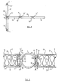
- a plurality of panels 10 as described hereinbefore with reference to Figures 2 and 3 are assembled together in a desired pattern, for example the T-shape as shown in Figure 1, tube T of the first edge members 14' of the panels 10 being positioned in contact with magnetised strips 28 of the second edge members 15' of an adjacent panel 10 so that the adjacent edge members 14', 15' are connected together by virtue of magnetic attraction between the magnetised rubber on the second edge members 15' and the magnetic material of the ferrous tubes T of the first members 14'.
- the panels 10 may be assembled in the configuration shown in Figure 4, where panels 10 are stacked on top of one another with the lower edge of one panel, 10a say, resting on the upper edge of a lower panel 10b as well as in edge-to-edge relationship with other panels 10c and 10d respectively.
- the tubes T of each panel 10a, 10b are connected by a spigot connection 35 as is shown in Figure 3, comprising a pair of cylindrical plugs 36, 37 of slightly smaller diameter than the internal diameter of the tubes T, the plugs 36, 37 being connected by a restricted grooved portion 38 in which an 0-ring 39 is received, to prevent the spigot 35 falling within the tube T of the lower panel.
- the 0-ring 38 is sandwiched between the tubes of the upper and lower panels 10a, lOb.
- a light fitting 44 such as shown in Figure 5 may conveniently be mounted in the upper open end of a tube T by virtue of a plug 35', similar to spigot 35, also having an 0-ring 39' in a groove 38'.
- a bracket 42 Located in the plug is a bracket 42 on which a light 43 is supported, the electric cable 46 for the light passing through the bracket 42 and then upwardly through the plug 39 and from the top of the plug 35' to a convenient electrical socket outlet (not shown).
- such a light fitting may illuminate the panels 10.
- the corner illustrated in Figure 4 utilises a further tube T' which is not attached to a panel 10 by self-tapping screws but is magnetically attached to the edge members 15' of the right hand panels 10c and 10d by the magnetic strip 28 of the extrusion of the right hand panel magnetically attracting the ferrous material of the tube T'.
- a long cross panel 10e is provided which is engaged with further short tubes Ts which are connected to the upper end of tube T' by a further spigot 35 and with the upper end of tube T of the left hand upper panel 10a by magnetic attraction to add rigidity to the corner display and to conceal the light fitting 44.
- the assembly need not be made free standing by arranging adjacent panels at varying angles as in the examples described, but feet means may be provided or other supports to retain the assembly in the position wherein the panels 10 are upright.
- the female second edge member 15' which has been described as comprising a strip 28 of magnetised material
- the male first member 14' may comprise magnetised material, e.g. tube T could be made of magnetised material, and the second member 15' provided with or made of magnetic material.
- both the female 15' and male 14' members could be made of magnetised material but with opposite directions of polarity.
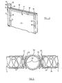
- both the edge members of each panel are of the same female configuration and construction as the second edge member 15' described with reference to Figures 2 and 3, and in this case an intermediate member comprising a ferrous metal tube 50 is provided which both the magnetised rubber strips 28 of each female member 15' magnetically attract.
- the angular circumferential extent of the female members 15' around the male member 50 it may be arranged for two or more than two panels 10 to be connected to a single intermediate member 50.
- the female members 15' attached to the panels 10 may be made of magnetic material and the intermediate member 50 be magnetised by any suitable means.
- edge members 14', 15' as plastic extrusions with a ferrous metal tube T, T' attached to extension 14'
- other types of magnetic attraction means may be provided which permit the panels 10 to be assembled in edge-to-edge relationship at varying angles between predetermined limits.
- a tube T may be directly adhered to one edge of the panel 10, and magnetised material provided on the opposite edge.
- the present invention provides an economical and convenient means whereby a desired array of display panels may be assembled together.
- the invention has the advantage that the assembly and disassembly of the display panels is simple, it merely being necessary to place the edge members in desired juxtaposition or in desired juxtaposition with an intermediate member where one is provided, and the display panels are automatically connected together by the magnetic forces arising. Further, the orientation of the adjacent panels may be varied as desired whilst assembled, to provide a wide range of configurations. Separate uprights and panels are thus not required to achieve a stable versatile display assembly. Shelves and the like may be attached to the panels 10 by brackets which engage above the upper edges 32 of the panels 10, or by brackets which engage the tubes T, as required.
Landscapes
- Engineering & Computer Science (AREA)
- Physics & Mathematics (AREA)
- Architecture (AREA)
- Electromagnetism (AREA)
- Civil Engineering (AREA)
- Structural Engineering (AREA)
- General Physics & Mathematics (AREA)
- Theoretical Computer Science (AREA)
- Devices For Indicating Variable Information By Combining Individual Elements (AREA)
Applications Claiming Priority (2)
| Application Number | Priority Date | Filing Date | Title |
|---|---|---|---|
| GB8039199 | 1980-12-06 | ||
| GB8039199 | 1980-12-06 |
Publications (1)
| Publication Number | Publication Date |
|---|---|
| EP0053933A1 true EP0053933A1 (fr) | 1982-06-16 |
Family
ID=10517812
Family Applications (1)
| Application Number | Title | Priority Date | Filing Date |
|---|---|---|---|
| EP19810305755 Withdrawn EP0053933A1 (fr) | 1980-12-06 | 1981-12-07 | Dispositifs d'affichage |
Country Status (2)
| Country | Link |
|---|---|
| EP (1) | EP0053933A1 (fr) |
| GB (1) | GB2090692B (fr) |
Cited By (8)
| Publication number | Priority date | Publication date | Assignee | Title |
|---|---|---|---|---|
| WO1987006973A1 (fr) * | 1986-05-07 | 1987-11-19 | Plan Design A/S | Barriere ou cloison et poteau ou montant associes |
| FR2656888A1 (fr) * | 1990-01-11 | 1991-07-12 | Parisato Roland | Systeme de cloisons demontables et modulables. |
| WO1992013157A1 (fr) * | 1991-01-28 | 1992-08-06 | Frames Design & Build Ltd. | Systeme de cadre articule |
| EP0598549A1 (fr) * | 1992-11-10 | 1994-05-25 | Wilson, Christopher Herbert Cecil | Eléments pour construction modulaire |
| AT400203B (de) * | 1993-08-30 | 1995-11-27 | Wagner Walter Ing | Plakatständer |
| EP0976884A1 (fr) * | 1998-07-31 | 2000-02-02 | PREFORM RAUMGLIEDERUNGSSYSTEME GmbH | Cloison mobile |
| WO2001035381A1 (fr) * | 1999-11-12 | 2001-05-17 | Expand International Ab | Systeme de presentation pliant |
| US11530535B2 (en) * | 2019-09-19 | 2022-12-20 | Kadeya Enterprise Co., Ltd | Dividing screen structure |
Families Citing this family (3)
| Publication number | Priority date | Publication date | Assignee | Title |
|---|---|---|---|---|
| GB2214961A (en) * | 1988-02-20 | 1989-09-13 | Duraflex Ltd | Roof; bay window |
| GB2444493B (en) * | 2006-12-06 | 2009-04-15 | Robert Henry Livock | Wing uprights for horse jumps |
| GB2468914B (en) * | 2009-03-27 | 2013-10-23 | Signwaves Ltd | Dividing systems and components thereof |
Citations (5)
| Publication number | Priority date | Publication date | Assignee | Title |
|---|---|---|---|---|
| GB653816A (en) * | 1941-06-18 | 1951-05-23 | Ragnar Mauritz Lublin | Improvements relating to portable screens or partitions |
| GB813060A (en) * | 1956-06-22 | 1959-05-06 | Frederick Orme | Improvements in or relating to holders for vehicle licences and the like |
| US3571999A (en) * | 1969-07-02 | 1971-03-23 | John G Downing | Knockdown display |
| FR2113766A7 (fr) * | 1970-11-13 | 1972-06-30 | Sitour Sa | |
| GB1397901A (en) * | 1972-07-06 | 1975-06-18 | Hueppe Justin | Soundabsorbing partition member |
-
1981
- 1981-12-07 EP EP19810305755 patent/EP0053933A1/fr not_active Withdrawn
- 1981-12-07 GB GB8136775A patent/GB2090692B/en not_active Expired
Patent Citations (5)
| Publication number | Priority date | Publication date | Assignee | Title |
|---|---|---|---|---|
| GB653816A (en) * | 1941-06-18 | 1951-05-23 | Ragnar Mauritz Lublin | Improvements relating to portable screens or partitions |
| GB813060A (en) * | 1956-06-22 | 1959-05-06 | Frederick Orme | Improvements in or relating to holders for vehicle licences and the like |
| US3571999A (en) * | 1969-07-02 | 1971-03-23 | John G Downing | Knockdown display |
| FR2113766A7 (fr) * | 1970-11-13 | 1972-06-30 | Sitour Sa | |
| GB1397901A (en) * | 1972-07-06 | 1975-06-18 | Hueppe Justin | Soundabsorbing partition member |
Cited By (16)
| Publication number | Priority date | Publication date | Assignee | Title |
|---|---|---|---|---|
| WO1987006973A1 (fr) * | 1986-05-07 | 1987-11-19 | Plan Design A/S | Barriere ou cloison et poteau ou montant associes |
| FR2656888A1 (fr) * | 1990-01-11 | 1991-07-12 | Parisato Roland | Systeme de cloisons demontables et modulables. |
| EP0439984A1 (fr) * | 1990-01-11 | 1991-08-07 | Roland Parisato | Système de cloisons démontables et modulables |
| WO1992013157A1 (fr) * | 1991-01-28 | 1992-08-06 | Frames Design & Build Ltd. | Systeme de cadre articule |
| US5411073A (en) * | 1991-01-28 | 1995-05-02 | Frames Design & Build Limited | Hinged frame system |
| EP0598549A1 (fr) * | 1992-11-10 | 1994-05-25 | Wilson, Christopher Herbert Cecil | Eléments pour construction modulaire |
| AT400203B (de) * | 1993-08-30 | 1995-11-27 | Wagner Walter Ing | Plakatständer |
| WO2000008270A1 (fr) * | 1998-07-31 | 2000-02-17 | Preform Raumgliederungssysteme Gmbh | Cloison mobile |
| EP0976884A1 (fr) * | 1998-07-31 | 2000-02-02 | PREFORM RAUMGLIEDERUNGSSYSTEME GmbH | Cloison mobile |
| AU742828B2 (en) * | 1998-07-31 | 2002-01-10 | Preform Holding D.O.O. | Mobile partition |
| US6415566B2 (en) | 1998-07-31 | 2002-07-09 | Preform Holding D.O.O. | Mobile partition |
| WO2001035381A1 (fr) * | 1999-11-12 | 2001-05-17 | Expand International Ab | Systeme de presentation pliant |
| US7237350B1 (en) | 1999-11-12 | 2007-07-03 | Expand International Ab | Collapsible display-arrangement |
| US8028449B2 (en) | 1999-11-12 | 2011-10-04 | Expand International Ab | Collapsible display-arrangement |
| US8615914B2 (en) | 1999-11-12 | 2013-12-31 | Expand International Ab | Collapsible display-arrangement |
| US11530535B2 (en) * | 2019-09-19 | 2022-12-20 | Kadeya Enterprise Co., Ltd | Dividing screen structure |
Also Published As
| Publication number | Publication date |
|---|---|
| GB2090692B (en) | 1984-07-04 |
| GB2090692A (en) | 1982-07-14 |
Similar Documents
| Publication | Publication Date | Title |
|---|---|---|
| US3997220A (en) | Display units | |
| US5172504A (en) | Front-mount grid display having trim strips and hook and loop | |
| EP0053933A1 (fr) | Dispositifs d'affichage | |
| US6718709B2 (en) | Snap panel display unit | |
| US6042243A (en) | Modular light box | |
| US4147198A (en) | Portable display system | |
| US4856216A (en) | Advertising cover for fluorescent lighting | |
| US4712336A (en) | Interconnecting "full bleed" modular panel and connective hardware system to form a variety of exhibit and office interior enclosures | |
| US4825601A (en) | Modular slotwall members | |
| US4926609A (en) | Exhibit display | |
| US5586593A (en) | Partitioning system | |
| US4553680A (en) | Display case | |
| US3559814A (en) | Folding table-top display | |
| US5544438A (en) | Card and picture holder | |
| US20040163778A1 (en) | Modular multi-configurable display system | |
| US3197822A (en) | Structural assemblies | |
| US5611384A (en) | Display system | |
| US4986038A (en) | Component exhibit system | |
| US4579308A (en) | Wall structure having plural spaced panels | |
| US4038790A (en) | Partition structure | |
| US5938365A (en) | Tubular frame with round corner members | |
| JPH0436006B2 (fr) | ||
| US6010015A (en) | Decorative compact disk rack | |
| US4467854A (en) | Connector for display systems | |
| US5393232A (en) | Visual aid system |
Legal Events
| Date | Code | Title | Description |
|---|---|---|---|
| PUAI | Public reference made under article 153(3) epc to a published international application that has entered the european phase |
Free format text: ORIGINAL CODE: 0009012 |
|
| AK | Designated contracting states |
Designated state(s): AT BE CH DE FR IT LU NL SE |
|
| 17P | Request for examination filed |
Effective date: 19821216 |
|
| STAA | Information on the status of an ep patent application or granted ep patent |
Free format text: STATUS: THE APPLICATION IS DEEMED TO BE WITHDRAWN |
|
| 18D | Application deemed to be withdrawn |
Effective date: 19850703 |
|
| RIN1 | Information on inventor provided before grant (corrected) |
Inventor name: BENNET, MALCOLM ARNOLD GRAHAM |