EP0053965A1 - Vorgespannte Betonkonstruktion, Verfahren zu deren Herstellung und Elemente zur Durchführung des Verfahrens - Google Patents
Vorgespannte Betonkonstruktion, Verfahren zu deren Herstellung und Elemente zur Durchführung des Verfahrens Download PDFInfo
- Publication number
- EP0053965A1 EP0053965A1 EP81401862A EP81401862A EP0053965A1 EP 0053965 A1 EP0053965 A1 EP 0053965A1 EP 81401862 A EP81401862 A EP 81401862A EP 81401862 A EP81401862 A EP 81401862A EP 0053965 A1 EP0053965 A1 EP 0053965A1
- Authority
- EP
- European Patent Office
- Prior art keywords
- structure according
- trellis
- plate
- bars
- elements
- Prior art date
- Legal status (The legal status is an assumption and is not a legal conclusion. Google has not performed a legal analysis and makes no representation as to the accuracy of the status listed.)
- Granted
Links
- 238000000034 method Methods 0.000 title claims abstract description 13
- 239000011513 prestressed concrete Substances 0.000 title claims abstract description 9
- 239000004567 concrete Substances 0.000 claims abstract description 22
- 238000009415 formwork Methods 0.000 claims description 7
- 239000007787 solid Substances 0.000 claims description 6
- 239000011150 reinforced concrete Substances 0.000 claims description 5
- 238000004873 anchoring Methods 0.000 claims description 4
- 238000009417 prefabrication Methods 0.000 claims 2
- 230000005540 biological transmission Effects 0.000 claims 1
- 238000010276 construction Methods 0.000 abstract description 7
- 238000010586 diagram Methods 0.000 description 2
- 238000004519 manufacturing process Methods 0.000 description 2
- 206010040954 Skin wrinkling Diseases 0.000 description 1
- 239000011248 coating agent Substances 0.000 description 1
- 238000000576 coating method Methods 0.000 description 1
- 238000007796 conventional method Methods 0.000 description 1
- 230000000284 resting effect Effects 0.000 description 1
- 238000009416 shuttering Methods 0.000 description 1
Images






Classifications
-
- E—FIXED CONSTRUCTIONS
- E01—CONSTRUCTION OF ROADS, RAILWAYS, OR BRIDGES
- E01D—CONSTRUCTION OF BRIDGES, ELEVATED ROADWAYS OR VIADUCTS; ASSEMBLY OF BRIDGES
- E01D2/00—Bridges characterised by the cross-section of their bearing spanning structure
- E01D2/04—Bridges characterised by the cross-section of their bearing spanning structure of the box-girder type
-
- E—FIXED CONSTRUCTIONS
- E01—CONSTRUCTION OF ROADS, RAILWAYS, OR BRIDGES
- E01D—CONSTRUCTION OF BRIDGES, ELEVATED ROADWAYS OR VIADUCTS; ASSEMBLY OF BRIDGES
- E01D2/00—Bridges characterised by the cross-section of their bearing spanning structure
-
- E—FIXED CONSTRUCTIONS
- E01—CONSTRUCTION OF ROADS, RAILWAYS, OR BRIDGES
- E01D—CONSTRUCTION OF BRIDGES, ELEVATED ROADWAYS OR VIADUCTS; ASSEMBLY OF BRIDGES
- E01D2101/00—Material constitution of bridges
- E01D2101/20—Concrete, stone or stone-like material
- E01D2101/24—Concrete
- E01D2101/26—Concrete reinforced
- E01D2101/28—Concrete reinforced prestressed
Definitions
- the invention relates to a prestressed concrete structure having a hollow slab behavior, in particular for constituting a bridge deck, a covering or a floor.
- the object of the invention is to combine a trellis structure and prestressing by external cable to maximize the advantages of these two techniques.
- the structure of the invention which comprises two plates of reinforced or prestressed concrete arranged opposite and connected by a multidirectional lattice disposed in the volume between the plates, is characterized in particular in that said lattice consists of rigid prefabricated elements in reinforced or prestressed concrete, each comprising at least one group of at least two bars and at least one cross member arranged along the three sides of a triangle, and in that the structure comprises concrete blocks located between the two plates and integral with at least one of the plates, and cables for prestressing the structure anchored at their ends in some of the massifs and passing inside said volume and / or in the vicinity of the plates while remaining at the exterior of the trellis concrete.
- the invention also relates to a method for producing such a structure from these trellis elements.
- At least one plate is prefabricated having reserves suitable for each receiving a meeting point of two bars of a trellis element, there are prefabricated trellis elements on the plate so that the chosen meeting points are placed in the reserves, concrete is poured into the reserves around said points to form nodes and secure the plate and the lattice elements in a rigid transportable unit.
- some of the cross members of the trellis elements are used to produce the difficult part of the formwork of the other plate of the structure, the rest of the formwork being achievable by means of formwork simply slid between the elements of trellis parallel to the length of the structure.
- some of the crosspieces of the trellis elements follow each other by forming a line which extends over part or the entire length of a plate which possibly includes places where two crosspieces are joined and which possibly meet with other lines.
- the bridge shown diagrammatically in FIG. 1 comprises, in a manner known per se, an deck made up of successive spans 1 and resting on end abutments 2,3 as well as on intermediate piers 4.
- the invention relates, firstly, to the structure of the bridge deck and, by way of example, a common span of the deck will be described below.
- This span established between two successive piers, comprises at each end a massif.
- the span deck is made up of two plates or “tables” of reinforced or prestressed concrete, respectively lower and upper, connected by a concrete triangulation.
- the assembly is prestressed by cables which run from one block to another passing through the volume of the triangulation but outside the concrete of the triangulation, and under the concrete of the lower table thanks to the provided passages for this purpose.
- Figure 2 is a longitudinal section through the span in the region of the front end of the span.
- the front massif 5 of the span located between the two tables 6,7 and forming a body with them.
- the cable 8, at its exit from the block passes through the volume of the triangulation then in a passage 10 formed in the lower table 6; it then undergoes a deviation and then goes straight along table 6; further on, it will be deflected in the opposite direction, will go up in the volume occupied by the triangulation then will lead to the solid mass located at the other end of the span.
- Figure 3 is a longitudinal section of the deck at a place where the cable 9, in turn, passes through a passage 11 of the lower table, then spins straight along the table.
- Figure 4 is a longitudinal section of the apron at another location where the two cables 8,9 go up in the volume of the triangulation.
- Figure 5 is a longitudinal section of the other end (or rear end) of the span which shows the other block 12 located between the tables and integral with them.
- Anchoring blocks are normally provided on the end abutments of the bridge.
- Figure 6 shows for example an anchor block 5 on the abutment 3 of the front end of the bridge.
- anchoring or cable passage masses - prestressing preferably consist essentially of concrete veils or plates, as is best shown in FIG. 7 which is a half cross-section of a massif such as 12.
- the massif is made up of several sections which each include a vertical veil or central plate 14 and side veils or plates. obliques 15,16, the three sails or plates being arranged in crow's feet.
- FIG. 8 which is a longitudinal section of the massif, it can be seen that the central veil 14 has an extent. significantly larger than the side sails.
- the prestressing cables pass or are anchored in the central web 14.
- the cable passage plane is designated at 17 in FIG. 7.
- the solid masses on the abutment have a similar structure.
- the invention also relates to a particular embodiment of triangulation.
- the triangulation is preferably a structure made up of concrete bars which may have a small cross section because the prestressing cables pass outside the concrete of the bars.
- the bars meet the tables at places or "nodes" whose shapes are designed to deflect the prestressing cables, as necessary.
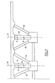
- Figure 9 which is a current cross section of the deck (or in other words, a section in the length of a segment) shows the bars 18 of the triangulation which lead to nodes 19,20, respectively in the lower table 6 and in the upper table 7. Some of the knots have grooves 21 through which the prestressing cables such as cables 8 and 9 can pass.
- the tables include, as necessary, ribs which have passages cooperating with the grooves of the nodes to guide and deflect the prestressing cables, either along the table or through the table.
- FIGS. 10 and 11 are longitudinal longitudinal sections of the lower table at two successive locations and in FIG. 12 which shows transverse vertical sections made in these locations.
- FIG. 10 and 11 the bars of the triangulation have been disregarded.
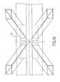
- Figures 13 and 14 respectively show a node of the lower table seen from above, and a node of the upper table seen from below.
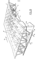
- Figure 15 a schematic perspective of a portion of the deck.
- the arrow 23 designates in the figure the direction which extends the bridge. We find in this figure some of the characteristics which have been described previously as well as other characteristics which will be mentioned below.
- the structure also includes prestressing cables 8 ', 9', which extend transversely (while the cables such as 8 and 9 extend longitudinally) and which are anchored in solid masses or concrete sails, such as for example the veil 24 located between the tables 6,7 and being integral with them.
- prestressing cables 8 ', 9' which extend transversely (while the cables such as 8 and 9 extend longitudinally) and which are anchored in solid masses or concrete sails, such as for example the veil 24 located between the tables 6,7 and being integral with them.
- These transverse cables like the longitudinal cables, pass outside the concrete of the bars 18 of the triangulation and are deflected at the locations of some of the nodes of the lower table.
- the prestressing cables can pass in the vicinity of the upper table instead of passing in the vicinity of the lower table.
- the cables when they pass under the lower table or above the upper table, do not deviate from it more than a distance equal to a fraction of the distance of the two tables, for example a distance equal to one tenth of the distance between the tables.
- the cables are mainly located between the tables.
- the invention also relates, as has already been indicated, to a technique for constructing the bridge deck.
- the basic element is generally a rigid trellis element which, in a typical example, consists of two bars 18 and a crosspiece 25 arranged along the lines. three sides of a triangle as seen in Figure 16.
- the shape of the cross-section of the bars is indifferent: square, rectangular, oval, etc.
- FIG. 17 schematically illustrates the production of a trellis pyramid by means of trellis elements as described above.
- the pyramid is constituted by means of four elements A, B, C, D which are arranged so that each trellis element provides a bar arranged along one of the edges of the pyramid.
- the four elements A , B, C, D are arranged in pairs in two oblique planes, the meeting points of the bars of the elements being brought together to form the top of the pyramid, the two elements of a couple having their two crossbars 25 aligned and two bars 18 juxtaposed, the two other bars 18 being arranged along two edges of the pyramid.
- the top of the pyramid is housed in a reserve 26 of a plate and concrete is poured around the reserve to form a knot around this top and lock the pyramid in position.
- the trellis elements are held by any suitable means. If necessary, the two couples are and remain temporarily braced until complete stiffening.
- pyramidal configuration can be obtained with other trellis elements and that this shape, while being preferred, is not limiting.
- pyramids P appear in FIG. 15 except in the foreground which passes into the median plane of a file of pyramids and which consequently shows only two elements of each pyramid.
- the sleepers do not intervene in the function of the trellis, their role is to maintain the bars in the desired arrangement during the completion of the work and to serve as formwork for shuttering the parts of the upper plate which, ordinarily, are difficult to form.
- the prestressing cables are possibly protected, for example by a concrete coating which cannot be confused with the concrete of the triangulation.
- the invention makes it possible to achieve significant savings in concrete, up to 30%, in the construction of a bridge.
- the efficiency defined by the ratio between the height of the vertical range through which the pressure line must pass (due to the prestressing, the weight of the structure and the operating loads) and the total height of the structure (that is to say the height of the hollowed slab) can reach 0.65 to 0.95 according to the teachings of the invention, instead of remaining in the range 0.35-0, 55 obtained by conventional methods.
Landscapes
- Engineering & Computer Science (AREA)
- Architecture (AREA)
- Civil Engineering (AREA)
- Structural Engineering (AREA)
- Bridges Or Land Bridges (AREA)
- Rod-Shaped Construction Members (AREA)
- Reinforcement Elements For Buildings (AREA)
- Conveying And Assembling Of Building Elements In Situ (AREA)
Priority Applications (1)
| Application Number | Priority Date | Filing Date | Title |
|---|---|---|---|
| AT81401862T ATE16616T1 (de) | 1980-11-25 | 1981-11-24 | Vorgespannte betonkonstruktion, verfahren zu deren herstellung und elemente zur durchfuehrung des verfahrens. |
Applications Claiming Priority (2)
| Application Number | Priority Date | Filing Date | Title |
|---|---|---|---|
| FR8024984A FR2494741A1 (fr) | 1980-11-25 | 1980-11-25 | Structure precontrainte en beton comprenant deux plaques reliees par un treillis, procede pour la fabriquer, elements pour la mise en oeuvre du procede et application a la construction d'un element de tablier de pont, de couverture ou de plancher |
| FR8024984 | 1980-11-25 |
Publications (2)
| Publication Number | Publication Date |
|---|---|
| EP0053965A1 true EP0053965A1 (de) | 1982-06-16 |
| EP0053965B1 EP0053965B1 (de) | 1985-11-21 |
Family
ID=9248327
Family Applications (1)
| Application Number | Title | Priority Date | Filing Date |
|---|---|---|---|
| EP81401862A Expired EP0053965B1 (de) | 1980-11-25 | 1981-11-24 | Vorgespannte Betonkonstruktion, Verfahren zu deren Herstellung und Elemente zur Durchführung des Verfahrens |
Country Status (6)
| Country | Link |
|---|---|
| US (1) | US4620400A (de) |
| EP (1) | EP0053965B1 (de) |
| AT (1) | ATE16616T1 (de) |
| CA (1) | CA1176071A (de) |
| DE (1) | DE3173017D1 (de) |
| FR (1) | FR2494741A1 (de) |
Cited By (8)
| Publication number | Priority date | Publication date | Assignee | Title |
|---|---|---|---|---|
| FR2546202A1 (fr) * | 1983-05-16 | 1984-11-23 | Bouygues Sa | Pont a voussoirs prefabiques et a precontrainte exterieure par cables, voussoirs pour ce pont et procedes de fabrication de ces voussoirs |
| EP0144271A1 (de) * | 1983-12-07 | 1985-06-12 | Bouygues | Brückengitter, Brückenfeld so ein Gitter enthaltend, und Verfahren zum Hestellen des Feldes |
| FR2564507A1 (fr) * | 1984-05-18 | 1985-11-22 | Calculs Ouvrage Art Et | Montant pour poutre a ame evidee, poutres et ouvrages comportant de tels montants |
| FR2612963A1 (fr) * | 1987-03-27 | 1988-09-30 | Muller Jean | Pont constitue d'un tablier et de moyens pour le supporter, notamment pont haubane de grande portee et son procede de construction |
| DE3833202A1 (de) * | 1988-09-30 | 1990-04-12 | Dyckerhoff & Widmann Ag | Balkenartiges tragglied aus spannbeton |
| GB2281572A (en) * | 1991-05-31 | 1995-03-08 | Alfred Alphonse Yee | Truss for e.g. bridges |
| US6211576B1 (en) | 1998-09-18 | 2001-04-03 | Hitachi, Ltd. | Semiconductor device |
| WO2018130633A1 (en) | 2017-01-16 | 2018-07-19 | Novo Nordisk A/S | Drive arrangement with rotationally geared drive rod |
Families Citing this family (18)
| Publication number | Priority date | Publication date | Assignee | Title |
|---|---|---|---|---|
| FR2546930B2 (fr) * | 1980-11-25 | 1986-04-18 | Bouygues Sa | Structure precontrainte en beton, procede pour la fabriquer et elements pour la mise en oeuvre du procede |
| JPH0757972B2 (ja) * | 1988-05-26 | 1995-06-21 | 清水建設株式会社 | トラス構造 |
| DE3902793A1 (de) * | 1989-01-31 | 1990-08-02 | Ibs Integriertes Bauen | Bauelement zur erstellung von gebaeuden, gebaeudeteilen od. dgl. |
| US5144710A (en) * | 1991-02-28 | 1992-09-08 | Grossman Stanley J | Composite, prestressed structural member and method of forming same |
| ATE182195T1 (de) * | 1993-05-01 | 1999-07-15 | Maunsell Structural Plastics | Baukonstruktion |
| DE4337193A1 (de) * | 1993-10-30 | 1995-05-04 | Karl Heinz Vahlbrauk | Gebäude |
| IT1266784B1 (it) * | 1993-11-09 | 1997-01-21 | Dlc Srl | Solaio industriale prefabbricato |
| US5651154A (en) * | 1995-11-13 | 1997-07-29 | Reynolds Metals Company | Modular bridge deck system consisting of hollow extruded aluminum elements |
| AU7735096A (en) * | 1995-11-13 | 1997-06-05 | Reynolds Metals Company | Modular bridge deck system including hollow extruded aluminum elements securely mounted to support girders |
| JP3732468B2 (ja) * | 2002-09-04 | 2006-01-05 | 朝日エンヂニヤリング株式会社 | トラス橋又はアーチ橋の補強構造 |
| KR100572860B1 (ko) * | 2005-01-11 | 2006-04-26 | (주)리튼브릿지 | 관통공이 형성된 가로보를 이용한 장지간 가설교량 |
| US7296317B2 (en) * | 2006-02-09 | 2007-11-20 | Lawrence Technological University | Box beam bridge and method of construction |
| US8020235B2 (en) * | 2008-09-16 | 2011-09-20 | Lawrence Technological University | Concrete bridge |
| US9309634B2 (en) | 2012-04-06 | 2016-04-12 | Lawrence Technological University | Continuous CFRP decked bulb T beam bridges for accelerated bridge construction |
| CN104805769B (zh) * | 2015-04-07 | 2016-08-24 | 中铁第五勘察设计院集团有限公司 | 一种自平衡弧形梁现浇支架及其施工方法 |
| AT520386B1 (de) * | 2017-08-24 | 2019-10-15 | Univ Wien Tech | Verfahren zur Herstellung einer integralen Brücke und integrale Brücke |
| CN111236049A (zh) * | 2020-03-16 | 2020-06-05 | 中铁二院工程集团有限责任公司 | 一种体外预应力转向构造 |
| CN112482224B (zh) * | 2020-11-16 | 2022-07-12 | 中铁大桥局集团有限公司 | 一种钢桁梁检查车轨道安装的施工方法 |
Citations (8)
| Publication number | Priority date | Publication date | Assignee | Title |
|---|---|---|---|---|
| BE571208A (de) * | ||||
| FR798928A (fr) * | 1934-12-07 | 1936-05-29 | Système porteur, en particulier pour ponts à poutres | |
| FR816180A (fr) * | 1936-01-11 | 1937-08-02 | Poutres en béton armé | |
| DE839044C (de) * | 1950-02-26 | 1952-05-15 | E H Dr Ing E H Dr Ing Franz Di | Durch Haengewerke vorgespannter Stahlbeton-Durchlauftraeger mit nachtraeglichem Verbund |
| FR1008512A (fr) * | 1948-04-22 | 1952-05-19 | Dyckerhoff & Widmann Ag | Pont-poutre en béton armé, et procédé pour sa construction |
| CH401120A (de) * | 1961-05-13 | 1965-10-31 | Beteiligungs & Patentverw Gmbh | Isotroper Tragkörper |
| FR2111558A5 (de) * | 1970-10-20 | 1972-06-02 | Combinatie Westerschelde | |
| DE2519664A1 (de) * | 1975-05-02 | 1976-11-04 | Zueblin Ag | Raeumliches fachwerk |
Family Cites Families (22)
| Publication number | Priority date | Publication date | Assignee | Title |
|---|---|---|---|---|
| BE566546A (de) * | ||||
| NL60490C (de) * | 1900-01-01 | |||
| US183291A (en) * | 1876-10-17 | Improvement in girders for bridges | ||
| US948215A (en) * | 1909-05-06 | 1910-02-01 | Eugene F Fitzpatrick | Fireproof arch. |
| FR503513A (fr) * | 1917-06-07 | 1920-06-12 | John Woolcock | Perfectionnements à la construction de planchers, plafonds, etc. |
| FR680547A (fr) * | 1928-10-02 | 1930-05-01 | Procédé de fabrication de pièces en béton armé | |
| US1874572A (en) * | 1930-02-17 | 1932-08-30 | Max A Montgomery | Trussed structure |
| US2053135A (en) * | 1935-10-25 | 1936-09-01 | Gen Electric | Fabricated slab |
| US2101538A (en) * | 1936-03-14 | 1937-12-07 | Faber Herbert Alfred | Floor construction |
| GB612242A (en) * | 1946-05-21 | 1948-11-10 | Standard Telephones Cables Ltd | Improvements in or relating to electrical welding equipment |
| US2925727A (en) * | 1954-08-11 | 1960-02-23 | Gilbert Ash Ltd | Prestressed concrete floor, roof and like structures |
| US3103025A (en) * | 1958-12-03 | 1963-09-10 | Kaiser Aluminium Chem Corp | Structural unit |
| US3156018A (en) * | 1961-12-21 | 1964-11-10 | John H Slayter | Plant-manufactured building structure |
| US3257764A (en) * | 1962-09-27 | 1966-06-28 | Reynolds Metals Co | Bridge construction with girder having triangular intermediate and rectangular end cross-sectional configurations |
| DE1459677A1 (de) * | 1964-02-20 | 1969-05-08 | Krupp Gmbh | Fahrbahnplatte |
| US3561178A (en) * | 1967-11-02 | 1971-02-09 | Dyckerhoff & Widmann Ag | Bridge supporting structure having reinforced concrete elements formed along a catenary line |
| US3794433A (en) * | 1971-07-08 | 1974-02-26 | Schupack Ass | Segmental precast concrete post-tensioned overpass bridges with cantilevered abutment |
| SU426023A1 (de) * | 1972-05-18 | 1974-04-30 | , экспериментального проектировани | |
| BE810043A (fr) * | 1974-01-22 | 1974-05-16 | Procede de mise en precontrainte et en contreflexion de poutres mixtes en acier et beton. | |
| US4200946A (en) * | 1978-11-16 | 1980-05-06 | Westland Aircraft Limited | Load-supporting structures |
| US4282619A (en) * | 1979-11-16 | 1981-08-11 | Havens Steel Company | Truss structure |
| AT371869B (de) * | 1980-03-21 | 1983-08-10 | Baugesellschaft M B H Konrad B | Verfahren zur errichtung von hohlbogentragwerken, insbesondere bogenbruecken |
-
1980
- 1980-11-25 FR FR8024984A patent/FR2494741A1/fr active Granted
-
1981
- 1981-11-24 DE DE8181401862T patent/DE3173017D1/de not_active Expired
- 1981-11-24 EP EP81401862A patent/EP0053965B1/de not_active Expired
- 1981-11-24 AT AT81401862T patent/ATE16616T1/de not_active IP Right Cessation
- 1981-11-25 CA CA000390922A patent/CA1176071A/en not_active Expired
-
1984
- 1984-09-25 US US06/654,531 patent/US4620400A/en not_active Expired - Fee Related
Patent Citations (8)
| Publication number | Priority date | Publication date | Assignee | Title |
|---|---|---|---|---|
| BE571208A (de) * | ||||
| FR798928A (fr) * | 1934-12-07 | 1936-05-29 | Système porteur, en particulier pour ponts à poutres | |
| FR816180A (fr) * | 1936-01-11 | 1937-08-02 | Poutres en béton armé | |
| FR1008512A (fr) * | 1948-04-22 | 1952-05-19 | Dyckerhoff & Widmann Ag | Pont-poutre en béton armé, et procédé pour sa construction |
| DE839044C (de) * | 1950-02-26 | 1952-05-15 | E H Dr Ing E H Dr Ing Franz Di | Durch Haengewerke vorgespannter Stahlbeton-Durchlauftraeger mit nachtraeglichem Verbund |
| CH401120A (de) * | 1961-05-13 | 1965-10-31 | Beteiligungs & Patentverw Gmbh | Isotroper Tragkörper |
| FR2111558A5 (de) * | 1970-10-20 | 1972-06-02 | Combinatie Westerschelde | |
| DE2519664A1 (de) * | 1975-05-02 | 1976-11-04 | Zueblin Ag | Raeumliches fachwerk |
Non-Patent Citations (1)
| Title |
|---|
| Travaux, No. 561, Decembre 1981 Paris (FR) M. VIRLOGEUX: "Developpement de l'Innovation Dans le Domane des Grands Ouvrages", pages 39-55. e page 53, colonne de droite, lignes 10-15; page 54, colonne de gauche, lignes 1-21; figures 41,42 * * |
Cited By (14)
| Publication number | Priority date | Publication date | Assignee | Title |
|---|---|---|---|---|
| FR2546202A1 (fr) * | 1983-05-16 | 1984-11-23 | Bouygues Sa | Pont a voussoirs prefabiques et a precontrainte exterieure par cables, voussoirs pour ce pont et procedes de fabrication de ces voussoirs |
| EP0127515A1 (de) * | 1983-05-16 | 1984-12-05 | Bouygues | Brücke in Segmentbauweise und mit Vorspannung durch Aussenspannglieder, Segmente für diese Brücke und Verfahren zur Herstellung dieser Segmente |
| EP0144271A1 (de) * | 1983-12-07 | 1985-06-12 | Bouygues | Brückengitter, Brückenfeld so ein Gitter enthaltend, und Verfahren zum Hestellen des Feldes |
| FR2556377A1 (fr) * | 1983-12-07 | 1985-06-14 | Bouygues Sa | Treillis de pont, travee de pont comportant de tels treillis et procede pour construire la travee |
| FR2564507A1 (fr) * | 1984-05-18 | 1985-11-22 | Calculs Ouvrage Art Et | Montant pour poutre a ame evidee, poutres et ouvrages comportant de tels montants |
| WO1988007604A1 (fr) * | 1987-03-27 | 1988-10-06 | Jean Muller | Pont constitue d'un tablier et de moyens pour le supporter, notamment pont haubane de grande portee, et son procede de construction |
| FR2612963A1 (fr) * | 1987-03-27 | 1988-09-30 | Muller Jean | Pont constitue d'un tablier et de moyens pour le supporter, notamment pont haubane de grande portee et son procede de construction |
| EP0288350A1 (de) * | 1987-03-27 | 1988-10-26 | Societe Centrale D'etudes Et De Realisations Routieres- Scetauroute | Brücke, bestehend aus einem Deck und dessen Trägern, insbesondere Schrägseilbrücke und Verfahren zu ihrer Herstellung |
| US4993094A (en) * | 1987-03-27 | 1991-02-19 | Scetauroute | Bridge comprising a bridge floor and elements supporting said floor, particularly a long span cable-stayed bridge, and process of construction |
| JPH0733644B2 (ja) * | 1987-03-27 | 1995-04-12 | ミューラー.ジアン | 甲板及び該甲板を支持する要素とから成る橋、特に長スパンの斜張橋、並びにその構築方法 |
| DE3833202A1 (de) * | 1988-09-30 | 1990-04-12 | Dyckerhoff & Widmann Ag | Balkenartiges tragglied aus spannbeton |
| GB2281572A (en) * | 1991-05-31 | 1995-03-08 | Alfred Alphonse Yee | Truss for e.g. bridges |
| US6211576B1 (en) | 1998-09-18 | 2001-04-03 | Hitachi, Ltd. | Semiconductor device |
| WO2018130633A1 (en) | 2017-01-16 | 2018-07-19 | Novo Nordisk A/S | Drive arrangement with rotationally geared drive rod |
Also Published As
| Publication number | Publication date |
|---|---|
| FR2494741A1 (fr) | 1982-05-28 |
| ATE16616T1 (de) | 1985-12-15 |
| FR2494741B1 (de) | 1983-08-12 |
| EP0053965B1 (de) | 1985-11-21 |
| DE3173017D1 (en) | 1986-01-02 |
| US4620400A (en) | 1986-11-04 |
| CA1176071A (en) | 1984-10-16 |
Similar Documents
| Publication | Publication Date | Title |
|---|---|---|
| EP0053965B1 (de) | Vorgespannte Betonkonstruktion, Verfahren zu deren Herstellung und Elemente zur Durchführung des Verfahrens | |
| CA1292600C (fr) | Pont constitue d'un tablier et de moyens pour le supporter, notamment pont haubane de grande portee, et son procede de construction | |
| CA1319261C (fr) | Structures cellulaires pour murs de soutenement | |
| EP0340051B1 (de) | Brückentafel für eine Brücke mit grosser Spannweite | |
| FR2645585A1 (fr) | Ouvrage tubulaire souterrain et son procede de realisation | |
| EP0202256B2 (de) | VERFAHREN ZUR HERSTELLUNG EINER üBERDECKTEN KONSTRUKTION | |
| EP0329517B1 (de) | Schrägkabelbrücke und Verfahren zu deren Bau | |
| EP0381547B1 (de) | Verfahren zur Herstellung einer vergrabenen Leitung | |
| FR2620153A1 (fr) | Panneau de construction, notamment panneau de bardage, a isolation thermique integree | |
| EP0985071A1 (de) | Gebäudegerüst | |
| FR2642109A1 (fr) | Structure creuse allongee et son procede de fabrication | |
| EP2573268A1 (de) | Modulare Metallbrücke, und ihr Herstellungsverfahren | |
| FR2692924A1 (fr) | Structure porteuse telle qu'un plancher, comprenant des poutres et une dalle de béton et procédé pour son obtention. | |
| FR2482168A1 (fr) | Element d'armature pour la transmission des forces transversales dans des elements porteurs en forme de plaques, par exemple, des plafonds plats | |
| EP0004998A2 (de) | Baustruktur | |
| FR2956136A1 (fr) | Plancher en beton arme a elements porteurs integres | |
| FR2659368A1 (fr) | Structure tubulaire en beton, notamment pour structure en mer. | |
| FR2704253A1 (fr) | Procédé de construction de bâtiments à ossature de béton armé. | |
| EP4343079B1 (de) | Wandverbindungsbeschlag mit integrierter schalung | |
| FR2757889A1 (fr) | Planchers realises a partir de dalles prefabriquees permettant de transmettre des efforts horizontaux sans dalle de compression rapportee sur chantier | |
| EP1418283A1 (de) | Modulare Trägerstruktur | |
| FR2812323A1 (fr) | Piscine du type composee d'elements prefabriques en beton arme | |
| FR2530705A1 (fr) | Elements de construction pour la prefabrication notamment de planchers | |
| FR2900672A1 (fr) | Module d'habitation | |
| FR2728925A1 (fr) | Element de construction pour bassin |
Legal Events
| Date | Code | Title | Description |
|---|---|---|---|
| PUAI | Public reference made under article 153(3) epc to a published international application that has entered the european phase |
Free format text: ORIGINAL CODE: 0009012 |
|
| AK | Designated contracting states |
Designated state(s): AT BE CH DE FR GB IT LU NL SE |
|
| 17P | Request for examination filed |
Effective date: 19820623 |
|
| ITF | It: translation for a ep patent filed | ||
| GRAA | (expected) grant |
Free format text: ORIGINAL CODE: 0009210 |
|
| AK | Designated contracting states |
Designated state(s): AT BE CH DE FR GB IT LI LU NL SE |
|
| REF | Corresponds to: |
Ref document number: 16616 Country of ref document: AT Date of ref document: 19851215 Kind code of ref document: T |
|
| REF | Corresponds to: |
Ref document number: 3173017 Country of ref document: DE Date of ref document: 19860102 |
|
| PLBE | No opposition filed within time limit |
Free format text: ORIGINAL CODE: 0009261 |
|
| STAA | Information on the status of an ep patent application or granted ep patent |
Free format text: STATUS: NO OPPOSITION FILED WITHIN TIME LIMIT |
|
| 26N | No opposition filed | ||
| ITTA | It: last paid annual fee | ||
| EPTA | Lu: last paid annual fee | ||
| EAL | Se: european patent in force in sweden |
Ref document number: 81401862.8 |
|
| PGFP | Annual fee paid to national office [announced via postgrant information from national office to epo] |
Ref country code: NL Payment date: 19951017 Year of fee payment: 15 |
|
| PGFP | Annual fee paid to national office [announced via postgrant information from national office to epo] |
Ref country code: AT Payment date: 19951023 Year of fee payment: 15 |
|
| PGFP | Annual fee paid to national office [announced via postgrant information from national office to epo] |
Ref country code: LU Payment date: 19951101 Year of fee payment: 15 |
|
| PGFP | Annual fee paid to national office [announced via postgrant information from national office to epo] |
Ref country code: GB Payment date: 19951117 Year of fee payment: 15 |
|
| PGFP | Annual fee paid to national office [announced via postgrant information from national office to epo] |
Ref country code: SE Payment date: 19951122 Year of fee payment: 15 |
|
| PGFP | Annual fee paid to national office [announced via postgrant information from national office to epo] |
Ref country code: DE Payment date: 19951123 Year of fee payment: 15 |
|
| PGFP | Annual fee paid to national office [announced via postgrant information from national office to epo] |
Ref country code: FR Payment date: 19951128 Year of fee payment: 15 Ref country code: CH Payment date: 19951128 Year of fee payment: 15 |
|
| PGFP | Annual fee paid to national office [announced via postgrant information from national office to epo] |
Ref country code: BE Payment date: 19951208 Year of fee payment: 15 |
|
| PG25 | Lapsed in a contracting state [announced via postgrant information from national office to epo] |
Ref country code: LU Free format text: LAPSE BECAUSE OF NON-PAYMENT OF DUE FEES Effective date: 19961124 Ref country code: GB Effective date: 19961124 Ref country code: AT Effective date: 19961124 |
|
| PG25 | Lapsed in a contracting state [announced via postgrant information from national office to epo] |
Ref country code: SE Effective date: 19961125 |
|
| PG25 | Lapsed in a contracting state [announced via postgrant information from national office to epo] |
Ref country code: LI Effective date: 19961130 Ref country code: CH Effective date: 19961130 Ref country code: BE Effective date: 19961130 |
|
| BERE | Be: lapsed |
Owner name: BOUYGUES Effective date: 19961130 |
|
| PG25 | Lapsed in a contracting state [announced via postgrant information from national office to epo] |
Ref country code: NL Effective date: 19970601 |
|
| REG | Reference to a national code |
Ref country code: CH Ref legal event code: PL |
|
| GBPC | Gb: european patent ceased through non-payment of renewal fee |
Effective date: 19961124 |
|
| PG25 | Lapsed in a contracting state [announced via postgrant information from national office to epo] |
Ref country code: FR Effective date: 19970731 |
|
| NLV4 | Nl: lapsed or anulled due to non-payment of the annual fee |
Effective date: 19970601 |
|
| PG25 | Lapsed in a contracting state [announced via postgrant information from national office to epo] |
Ref country code: DE Effective date: 19970801 |
|
| EUG | Se: european patent has lapsed |
Ref document number: 81401862.8 |
|
| REG | Reference to a national code |
Ref country code: FR Ref legal event code: ST |