EP0053969A1 - Dispositif de support pour roue motrice et directrice de véhicule automobile - Google Patents
Dispositif de support pour roue motrice et directrice de véhicule automobile Download PDFInfo
- Publication number
- EP0053969A1 EP0053969A1 EP81401873A EP81401873A EP0053969A1 EP 0053969 A1 EP0053969 A1 EP 0053969A1 EP 81401873 A EP81401873 A EP 81401873A EP 81401873 A EP81401873 A EP 81401873A EP 0053969 A1 EP0053969 A1 EP 0053969A1
- Authority
- EP
- European Patent Office
- Prior art keywords
- hub
- wheel
- brake disc
- disc
- sealing part
- Prior art date
- Legal status (The legal status is an assumption and is not a legal conclusion. Google has not performed a legal analysis and makes no representation as to the accuracy of the status listed.)
- Granted
Links
- 238000007789 sealing Methods 0.000 claims abstract description 11
- 239000002184 metal Substances 0.000 claims abstract description 5
- 238000003754 machining Methods 0.000 description 1
- 239000000463 material Substances 0.000 description 1
Images
Classifications
-
- B—PERFORMING OPERATIONS; TRANSPORTING
- B60—VEHICLES IN GENERAL
- B60K—ARRANGEMENT OR MOUNTING OF PROPULSION UNITS OR OF TRANSMISSIONS IN VEHICLES; ARRANGEMENT OR MOUNTING OF PLURAL DIVERSE PRIME-MOVERS IN VEHICLES; AUXILIARY DRIVES FOR VEHICLES; INSTRUMENTATION OR DASHBOARDS FOR VEHICLES; ARRANGEMENTS IN CONNECTION WITH COOLING, AIR INTAKE, GAS EXHAUST OR FUEL SUPPLY OF PROPULSION UNITS IN VEHICLES
- B60K17/00—Arrangement or mounting of transmissions in vehicles
- B60K17/30—Arrangement or mounting of transmissions in vehicles the ultimate propulsive elements, e.g. ground wheels, being steerable
-
- B—PERFORMING OPERATIONS; TRANSPORTING
- B60—VEHICLES IN GENERAL
- B60B—VEHICLE WHEELS; CASTORS; AXLES FOR WHEELS OR CASTORS; INCREASING WHEEL ADHESION
- B60B27/00—Hubs
-
- F—MECHANICAL ENGINEERING; LIGHTING; HEATING; WEAPONS; BLASTING
- F16—ENGINEERING ELEMENTS AND UNITS; GENERAL MEASURES FOR PRODUCING AND MAINTAINING EFFECTIVE FUNCTIONING OF MACHINES OR INSTALLATIONS; THERMAL INSULATION IN GENERAL
- F16D—COUPLINGS FOR TRANSMITTING ROTATION; CLUTCHES; BRAKES
- F16D3/00—Yielding couplings, i.e. with means permitting movement between the connected parts during the drive
- F16D3/16—Universal joints in which flexibility is produced by means of pivots or sliding or rolling connecting parts
- F16D3/20—Universal joints in which flexibility is produced by means of pivots or sliding or rolling connecting parts one coupling part entering a sleeve of the other coupling part and connected thereto by sliding or rolling members
- F16D3/22—Universal joints in which flexibility is produced by means of pivots or sliding or rolling connecting parts one coupling part entering a sleeve of the other coupling part and connected thereto by sliding or rolling members the rolling members being balls, rollers, or the like, guided in grooves or sockets in both coupling parts
- F16D3/223—Universal joints in which flexibility is produced by means of pivots or sliding or rolling connecting parts one coupling part entering a sleeve of the other coupling part and connected thereto by sliding or rolling members the rolling members being balls, rollers, or the like, guided in grooves or sockets in both coupling parts the rolling members being guided in grooves in both coupling parts
-
- F—MECHANICAL ENGINEERING; LIGHTING; HEATING; WEAPONS; BLASTING
- F16—ENGINEERING ELEMENTS AND UNITS; GENERAL MEASURES FOR PRODUCING AND MAINTAINING EFFECTIVE FUNCTIONING OF MACHINES OR INSTALLATIONS; THERMAL INSULATION IN GENERAL
- F16D—COUPLINGS FOR TRANSMITTING ROTATION; CLUTCHES; BRAKES
- F16D3/00—Yielding couplings, i.e. with means permitting movement between the connected parts during the drive
- F16D3/84—Shrouds, e.g. casings, covers; Sealing means specially adapted therefor
Definitions
- the present invention relates to a support device for a driving and steering wheel of a motor vehicle comprising a hollow hub constituting the external element of a universal ball joint, for example of the RZEPPA type, the internal element of which is integral with a shaft. drive, a sheet metal sealing part being provided at the open end of the hub, opposite the seal.
- the sealing part is formed by a simple sheet metal provided with a flange and fitted into the open end of the hub.
- the present invention relates to a support device for a driving and driving wheel of a motor vehicle, of the type previously indicated and in which the brake disc is centered in a particularly simple and economical manner, which allows both a saving of material and, consequently, of weight, while avoiding machining of the range of the brake disc.
- the device according to the invention is characterized in that, known per se, the brake disc is fixed on the hub on the same side as the wheel, and in that the sealing part has the shape of a bowl, the closed end of which is fitted into the hollow hub and the length of which is such that the other end, of outside diameter substantially equal to the inside diameter of the brake disc, opens out of the hollow hub and passes through the disc by centering this one.
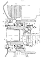
- the support device comprises a hollow wheel hub 1, on the internal surface of which tracks 2 are machined so as to constitute the external element of a universal joint 3 with balls 4, for example of the RZEPPA type , whose inner element 5 is secured to a drive shaft 6.
- the hub 1 is supported by means of a ball bearing 7 whose inner ring is formed by the hub while its outer ring 8 is secured to a support 9.
- a brake disc 10 and a wheel 11 are fixed to the hub 1 by screws 12 with conical head 12a which pass through openings 13 of the brake disc and through conical openings 14 of the wheel.
- a sealing piece 15 of stamped sheet metal is provided at the open end of the hub opposite the seal.
- the sealing part 15 has the shape of a bowl, the closed end of which is fitted into the opening 16 of the hub 1. It has an outside diameter substantially equal to the diameter of the opening 10a of the brake disc 10 and a a length such that, once fitted inside the hub 1, it exceeds by an amount at least equal to the thickness of the stack formed by the brake disc 10 and the web of the wheel 11.
- the brake disc 10 is fitted and centered on the sealing part 13 on which the wheel 11 is then pre-centered.
- the assembly is then fixed to the hub 1 by means of the fixing screws 12 screwed into the hub, the disc 10 being tightened. between this hub and the wheel 11, the final centering of which is achieved by means of the conical heads 12a of the screws 12 cooperating with the conical openings 14 of the wheel.
Landscapes
- Engineering & Computer Science (AREA)
- Mechanical Engineering (AREA)
- Chemical & Material Sciences (AREA)
- Combustion & Propulsion (AREA)
- Transportation (AREA)
- Braking Arrangements (AREA)
Abstract
Description
- La présente invention concerne un dispositif de support pour roue motrice et directrice de véhicule automobile comprenant un moyeu creux constituant l'élément extérieur d'un joint universel à billes, par exemple du type RZEPPA, dont l'élément intérieur est solidaire d'un arbre d'entraînement, une pièce d'étanchéité en tôle étant prévue à l'extrémité ouverte du moyeu, opposée au joint.
- Un dispositif de ce genre est décrit dans le brevet français 1 380 561. Dans ce dispositif, la pièce..d'étanchéité est constituée par une simple tôle munie d'un rebord et emmanchée dans l'extrémité ouverte du moyeu.
- Il est connu, par ailleurs, de fixer un disque de frein sur un flasque d'entraînement de la roue, du même côté que cette roue. Dans de tels dispositifs, le disque de frein peut être centré et la roue précentrée par un prolongement cylindrique du flasque.
- La présente invention a pour objet un dispositif de support pour roue directrice et motrice de véhicule automobile, du type précédemment indiqué et dans lequel le disque de frein est centré d'une manière particulièrement simple et économique, qui permet à la fois un gain de matière et, par suite, de poids, tout en évitant un usinage de la portée du disque de frein.
- Le dispositif selon l'invention est caractérisé en ce que, de ma- connue en soi, le disque de frein est fixé sur le moyeu du même côté que la roue, et en ce que la pièce d'étanchéité présente la forme d'un bol dont l'extrémité fermée est emmanchée dans le moyeu creux et dont la longueur est telle que l'autre extrémité, de diamètre extérieur sensiblement égal au diamètre intérieur du disque de frein, débouche hors du moyeu creux et traverse le disque en centrant celui-ci.
- On a décrit ci-après, à titre d'exemple non limitatif, un mode de réalisation du dispositif de support selon l'invention, avec référence à la figure unique du dessin annexé qui en est une vue en coupe axiale.
- Le dispositif de support conforme à l'invention comporte un moyeu de roue creux 1, sur la surface interne duquel sont usinées des pistes 2 de manière à constituer l'élément extérieur d'un joint universel 3 à billes 4, par exemple du type RZEPPA, dont l'élément intérieur 5 est solidaire d'un arbre de transmission 6. Le moyeu 1 est supporté au moyen d'un roulement à billes 7 dont la bague intérieure est constituée par le moyeu tandis que sa bague extérieure 8 est solidaire d'un support 9.
- Un disque de frein 10 et une roue 11 sont fixés sur le moyeu 1 par des vis 12 à tête conique 12a qui traversent des ouvertures 13 du disque de frein et des ouvertures coniques 14 de la roue. Une pièce d'étanchéité 15 en tôle emboutie est prévue à l'extrémité ouverte du moyeu opposée au joint.
- La pièce d'étanchéité 15 a la forme d'un bol dont l'extrémité fermée est emmanchée dans l'ouverture 16 du moyeu 1. Elle présente un diamètre extérieur sensiblement égal au diamètre de l'ouverture lOa du disque de frein 10 et a une longueur telle que, une fois emmanchée à l'intérieur du moyeu 1, elle dépasse d'une quantité au moins égale à l'épaisseur de l'empilage formé par le disque de frein 10 et le voile de la roue 11.
- Lors du montage, le disque de frein 10 est emmanché et centré sur la pièce d'étanchéité 13 sur laquelle la roue 11 est ensuite précentrée. L'ensemble est alors fixé sur le moyeu 1 au moyen des vis de fixation 12 vissées dans le moyeu, le disque 10 étant serré entre ce moyeu et la roue 11 dont le centrage final est réalisé au moyen des têtes coniques 12a des vis 12 coopérant avec les ouvertures coniques 14 de la roue.
- Il va de soi que la présente invention ne doit pas être considérée comme limitée au mode de réalisation décrit et représenté, mais en couvre, au contraire, toutes les variantes.
Claims (3)
Applications Claiming Priority (3)
| Application Number | Priority Date | Filing Date | Title |
|---|---|---|---|
| FR8026147A FR2495548B1 (fr) | 1980-12-05 | 1980-12-05 | Dispositif de support pour roue motrice et directrice de vehicule automobile |
| FR8026147 | 1980-12-05 | ||
| US06/323,083 US4421197A (en) | 1980-12-05 | 1981-11-19 | Device for supporting a steering and driving wheel of an automobile vehicle |
Publications (2)
| Publication Number | Publication Date |
|---|---|
| EP0053969A1 true EP0053969A1 (fr) | 1982-06-16 |
| EP0053969B1 EP0053969B1 (fr) | 1985-01-16 |
Family
ID=26222110
Family Applications (1)
| Application Number | Title | Priority Date | Filing Date |
|---|---|---|---|
| EP81401873A Expired EP0053969B1 (fr) | 1980-12-05 | 1981-11-26 | Dispositif de support pour roue motrice et directrice de véhicule automobile |
Country Status (3)
| Country | Link |
|---|---|
| US (1) | US4421197A (fr) |
| EP (1) | EP0053969B1 (fr) |
| FR (1) | FR2495548B1 (fr) |
Cited By (1)
| Publication number | Priority date | Publication date | Assignee | Title |
|---|---|---|---|---|
| FR2556287A1 (fr) * | 1983-12-08 | 1985-06-14 | Skf Ind Trading & Dev | Roulement de roue avec joint homocinetique et disque de frein incorpores |
Families Citing this family (17)
| Publication number | Priority date | Publication date | Assignee | Title |
|---|---|---|---|---|
| DE3140373A1 (de) * | 1981-10-10 | 1983-04-28 | Skf Kugellagerfabriken Gmbh, 8720 Schweinfurt | Radlagereinheit fuer angetriebene raeder von kraftfahrzeugen |
| NL8403209A (nl) * | 1984-10-22 | 1986-05-16 | Skf Ind Trading & Dev | Wentellager-constructie. |
| IT227543Y1 (it) * | 1992-05-05 | 1997-12-15 | Skf Ind Spa | Cuscinetto di rotolamento per un gruppo supporto ruota di un veicolo. |
| JP2002178707A (ja) * | 2000-12-14 | 2002-06-26 | Ntn Corp | 電気動力を車輪に伝達する車輪軸受 |
| DE10128073B4 (de) * | 2001-06-09 | 2009-12-24 | Daimler Ag | Radlagerung einer angetriebenen Starrachse |
| US6604794B1 (en) * | 2002-02-04 | 2003-08-12 | Meritor Heavy Vehicle Technology, Llc | Uni-pilot hub/drum system |
| US6733396B2 (en) | 2002-03-22 | 2004-05-11 | Delphi Technologies, Inc. | Constant velocity joint |
| JP2004162744A (ja) * | 2002-11-11 | 2004-06-10 | Honda Motor Co Ltd | アクスルハブのナックルへの支持構造 |
| DE602005022981D1 (de) * | 2005-04-29 | 2010-09-30 | Skf Ab | Radnabenlagereinheit |
| JP5079270B2 (ja) * | 2006-06-28 | 2012-11-21 | Ntn株式会社 | 車輪用軸受ユニット |
| WO2008007474A1 (fr) * | 2006-07-11 | 2008-01-17 | Ntn Corporation | Dispositif de support pour une roue |
| US20080169167A1 (en) * | 2007-01-11 | 2008-07-17 | Hyundai Mobis Co., Ltd. | Pulling type drive shaft-fitting jig assembly |
| DE102009027082B4 (de) * | 2009-06-22 | 2017-07-13 | Saf-Holland Gmbh | Radlageranordnung mit Mittenzentrierung |
| DE102012207050A1 (de) * | 2011-05-20 | 2012-11-22 | Schaeffler Technologies AG & Co. KG | Radlagergestaltung |
| FR3038542B1 (fr) * | 2015-07-06 | 2017-08-18 | Ntn-Snr Roulements | Moyeu de roue, roulement de roue, et assemblage de roue de vehicule |
| US10724592B2 (en) | 2017-04-20 | 2020-07-28 | Consolidated Metco, Inc. | High friction insulator |
| US12571441B2 (en) | 2020-05-05 | 2026-03-10 | Consolidated Metco, Inc. | Commercial vehicle brake rotor |
Citations (5)
| Publication number | Priority date | Publication date | Assignee | Title |
|---|---|---|---|---|
| GB191219035A (en) * | 1912-08-20 | 1913-06-19 | Peter Mcinnes | Improvements in Wheels for Road Vehicles. |
| FR1380561A (fr) * | 1963-10-03 | 1964-12-04 | Citroen Sa Andre | Perfectionnements aux pivots de roues avant des véhicules à essieu avant directeuret tracteur |
| FR1390345A (fr) * | 1964-01-14 | 1965-02-26 | Simca Automobiles Sa | Dispositif de fixation d'une fusée de roue motrice et directrice pour véhicule automobile |
| GB1343516A (en) * | 1972-10-23 | 1974-01-10 | British Leyland Austin Morris | Drive hub assemblies for motor vehicles |
| FR2407398A1 (fr) * | 1977-10-31 | 1979-05-25 | Klaue Hermann | Frein a disque, en particulier pour vehicules automobiles |
Family Cites Families (1)
| Publication number | Priority date | Publication date | Assignee | Title |
|---|---|---|---|---|
| DE2903229C2 (de) * | 1979-01-29 | 1981-04-02 | Uni-Cardan Ag, 5200 Siegburg | Einrichtung zur Befestigung eines Fahrzeugrades an einer über ein Gleichlaufdrehgelenk antreibbaren, an einem Radträger gelagerten Radnabe |
-
1980
- 1980-12-05 FR FR8026147A patent/FR2495548B1/fr not_active Expired
-
1981
- 1981-11-19 US US06/323,083 patent/US4421197A/en not_active Expired - Fee Related
- 1981-11-26 EP EP81401873A patent/EP0053969B1/fr not_active Expired
Patent Citations (5)
| Publication number | Priority date | Publication date | Assignee | Title |
|---|---|---|---|---|
| GB191219035A (en) * | 1912-08-20 | 1913-06-19 | Peter Mcinnes | Improvements in Wheels for Road Vehicles. |
| FR1380561A (fr) * | 1963-10-03 | 1964-12-04 | Citroen Sa Andre | Perfectionnements aux pivots de roues avant des véhicules à essieu avant directeuret tracteur |
| FR1390345A (fr) * | 1964-01-14 | 1965-02-26 | Simca Automobiles Sa | Dispositif de fixation d'une fusée de roue motrice et directrice pour véhicule automobile |
| GB1343516A (en) * | 1972-10-23 | 1974-01-10 | British Leyland Austin Morris | Drive hub assemblies for motor vehicles |
| FR2407398A1 (fr) * | 1977-10-31 | 1979-05-25 | Klaue Hermann | Frein a disque, en particulier pour vehicules automobiles |
Cited By (1)
| Publication number | Priority date | Publication date | Assignee | Title |
|---|---|---|---|---|
| FR2556287A1 (fr) * | 1983-12-08 | 1985-06-14 | Skf Ind Trading & Dev | Roulement de roue avec joint homocinetique et disque de frein incorpores |
Also Published As
| Publication number | Publication date |
|---|---|
| FR2495548B1 (fr) | 1986-05-09 |
| US4421197A (en) | 1983-12-20 |
| EP0053969B1 (fr) | 1985-01-16 |
| FR2495548A1 (fr) | 1982-06-11 |
Similar Documents
| Publication | Publication Date | Title |
|---|---|---|
| EP0053969B1 (fr) | Dispositif de support pour roue motrice et directrice de véhicule automobile | |
| EP0104108B1 (fr) | Dispositif de bras support d'une roue motrice | |
| FR2482013A1 (fr) | Montage de moyeu de roue commande par l'intermediaire d'un joint homocinetique, pour vehicule automobile | |
| WO1997015833A1 (fr) | Dispositif de fixation d'un capteur sur un palier a corps roulants | |
| FR2465119A1 (fr) | Butee de debrayage | |
| FR2531161A1 (fr) | Dispositif d'etancheite, notamment pour joint universel | |
| FR2470018A1 (fr) | Dispositif pour transmettre un couple entre un arbre d'entrainement, tel que le vilebrequin d'un moteur, et un appareil accessoire, tel qu'un ralentisseur hydrodynamique | |
| EP0669237A1 (fr) | Dispositif d'essuie-glace comportant des moyens perfectionnés d'accouplement entre l'arbre moteur et la tête d'entraînement | |
| WO1997042432A1 (fr) | Appareil d'accouplement hydrocinetique a piece d'entrainement de languettes, notamment pour vehicule automobile | |
| EP1070258B1 (fr) | Dispositif de fixation d'un capteur d'informations pour roulement ou palier | |
| FR2463875A1 (fr) | Dispositif de guidage a glissement pour l'etrier flottant d'un frein a disque | |
| FR2594752A1 (fr) | Dispositif pour le montage d'une roue motrice de vehicule automobile | |
| FR2560312A1 (fr) | Dispositif d'embrayage a disques de friction | |
| FR2808850A1 (fr) | Embrayage a friction rigide | |
| EP4281689B1 (fr) | Boitier de transmission et engin roulant equipe d'un tel boitier de transmission | |
| EP0612649A1 (fr) | Arbre de direction télescopique notamment pour véhicule automobile | |
| FR2557943A1 (fr) | Mecanisme d'embrayage destine a accoupler a volonte un volant et un arbre et dote d'une prise de mouvement pour entrainer en permanence un deuxieme arbre concentrique au premier | |
| FR2765932A1 (fr) | Mecanisme amortisseur comportant un roulement, notamment pour vehicule automobile, et procede de fixation de ce roulement | |
| EP0260196A1 (fr) | Dispositif de liaison entre un groupe moto-propulseur et un arbre de transmission de véhicule | |
| FR2730538A1 (fr) | Moyeu pivotant pour des dispositifs tendeurs, notamment des dispositifs tendeurs de courroies | |
| FR2665498A1 (fr) | Dispositif d'immobilisation d'un galet tendeur de courroie, chaine ou analogue, sur une surface d'appui appartenant par exemple a un carter de moteur de vehicule. | |
| FR2556658A1 (fr) | Dispositif de support d'une roue motrice d'un vehicule automobile | |
| FR2600134A2 (fr) | Dispositif de reglage de la position angulaire d'un organe comportant un moyeu sur un arbre, notamment d'un volant de direction sur un arbre de direction de vehicule automobile | |
| FR2858674A1 (fr) | Double volant amortisseur a volant primaire flexible | |
| FR2509411A1 (fr) | Poulie de variateur de vitesse |
Legal Events
| Date | Code | Title | Description |
|---|---|---|---|
| PUAI | Public reference made under article 153(3) epc to a published international application that has entered the european phase |
Free format text: ORIGINAL CODE: 0009012 |
|
| AK | Designated contracting states |
Designated state(s): DE GB IT |
|
| 17P | Request for examination filed |
Effective date: 19820717 |
|
| GRAA | (expected) grant |
Free format text: ORIGINAL CODE: 0009210 |
|
| AK | Designated contracting states |
Designated state(s): DE GB IT |
|
| ITF | It: translation for a ep patent filed | ||
| REF | Corresponds to: |
Ref document number: 3168400 Country of ref document: DE Date of ref document: 19850228 |
|
| REG | Reference to a national code |
Ref country code: GB Ref legal event code: 746 |
|
| ITPR | It: changes in ownership of a european patent |
Owner name: OFFERTA DI LICENZA AL PUBBLICO |
|
| PLBE | No opposition filed within time limit |
Free format text: ORIGINAL CODE: 0009261 |
|
| STAA | Information on the status of an ep patent application or granted ep patent |
Free format text: STATUS: NO OPPOSITION FILED WITHIN TIME LIMIT |
|
| 26N | No opposition filed | ||
| PGFP | Annual fee paid to national office [announced via postgrant information from national office to epo] |
Ref country code: GB Payment date: 19941118 Year of fee payment: 14 |
|
| PGFP | Annual fee paid to national office [announced via postgrant information from national office to epo] |
Ref country code: DE Payment date: 19941124 Year of fee payment: 14 |
|
| PG25 | Lapsed in a contracting state [announced via postgrant information from national office to epo] |
Ref country code: GB Effective date: 19951126 |
|
| GBPC | Gb: european patent ceased through non-payment of renewal fee |
Effective date: 19951126 |
|
| PG25 | Lapsed in a contracting state [announced via postgrant information from national office to epo] |
Ref country code: DE Effective date: 19960801 |