EP0054008B1 - Aus einem Strassentransportfahrzeug und einem abnehmbaren Bockgestell bestehende Anordnung für den Transport von Plattenförmigem Material - Google Patents
Aus einem Strassentransportfahrzeug und einem abnehmbaren Bockgestell bestehende Anordnung für den Transport von Plattenförmigem Material Download PDFInfo
- Publication number
- EP0054008B1 EP0054008B1 EP19810830242 EP81830242A EP0054008B1 EP 0054008 B1 EP0054008 B1 EP 0054008B1 EP 19810830242 EP19810830242 EP 19810830242 EP 81830242 A EP81830242 A EP 81830242A EP 0054008 B1 EP0054008 B1 EP 0054008B1
- Authority
- EP
- European Patent Office
- Prior art keywords
- frame
- channel
- ordinates
- vehicle
- unit according
- Prior art date
- Legal status (The legal status is an assumption and is not a legal conclusion. Google has not performed a legal analysis and makes no representation as to the accuracy of the status listed.)
- Expired
Links
- 239000000725 suspension Substances 0.000 claims description 16
- 238000005096 rolling process Methods 0.000 claims description 6
- 239000002184 metal Substances 0.000 claims description 5
- 210000002105 tongue Anatomy 0.000 claims description 4
- 230000000284 resting effect Effects 0.000 claims description 2
- 230000001174 ascending effect Effects 0.000 claims 1
- 210000005069 ears Anatomy 0.000 description 3
- 230000008901 benefit Effects 0.000 description 2
- 230000000903 blocking effect Effects 0.000 description 2
- 239000011521 glass Substances 0.000 description 2
- 210000001364 upper extremity Anatomy 0.000 description 2
- 230000007423 decrease Effects 0.000 description 1
- 238000004519 manufacturing process Methods 0.000 description 1
- 239000000463 material Substances 0.000 description 1
- 230000010355 oscillation Effects 0.000 description 1
- 230000006641 stabilisation Effects 0.000 description 1
- 238000011105 stabilization Methods 0.000 description 1
- 230000000087 stabilizing effect Effects 0.000 description 1
Images




Classifications
-
- B—PERFORMING OPERATIONS; TRANSPORTING
- B60—VEHICLES IN GENERAL
- B60P—VEHICLES ADAPTED FOR LOAD TRANSPORTATION OR TO TRANSPORT, TO CARRY, OR TO COMPRISE SPECIAL LOADS OR OBJECTS
- B60P3/00—Vehicles adapted to transport, to carry or to comprise special loads or objects
- B60P3/002—Vehicles adapted to transport, to carry or to comprise special loads or objects for carrying glass plates
Definitions
- the present invention relates to a known group, according to the preamble of claim 1, comprising a whole transport vehicle and a plate easel separate from the vehicle, in which the vehicle is provided with a channel for receiving the bridge which channel is bounded by side edges and open at the rear end of the vehicle, for loading and unloading the easel, and in which the easel essentially comprises an elongated base frame, a series of transverse ordinates which rise on the base frame and which have converging sides upwards to define on the two flanks of the bridge respective inclined faces for supporting the plates, and a ridge beam which connects the vertices of the ordinates.
- Groups of this kind have the disadvantage of using a vehicle specially designed for the transport of easels and unusable for other jobs.
- the easels used to transport glass plates and other fragile materials on trucks and other vehicles with a receiving channel have the disadvantage of occupying, when they do not transport plates, all the space they occupy on the vehicle during the transport of the plates.
- the vehicle makes a return journey after having deposited its load the presence of the easel largely prohibits loading on the vehicle of other goods to benefit from the return journey.
- the present invention aims to remedy these drawbacks.
- each lateral edge of the channel has, in its upper part, a lowered longitudinal zone, directed towards inside the canal, these lowered areas serving as support for the ends of removable transverse planks covering the canal, and by the fact that, in the easel, the ordinates are articulated both to the base frame and to the beam ridge along respective transverse axes, so as to allow the folding down of the ordinates themselves between an upright service arrangement and a provision folded down substantially horizontally on the base frame, retaining means being deprived to maintain the ordinates in the upright position, and the easel, with the ordinates in the folded position, can be received entirely in the vehicle channel, under the cover boards.
- a vehicle with a channel for loading a plate rack can be transformed into a vehicle with a tray, formed by the boards, for the transport of various goods.
- the vehicle can transport the easel folded and enclosed in the channel covered by the boards.
- a semi-trailer indicated as a whole by 10 comprises a load channel 12 delimited by a lower load plane 14 and by lateral flanges 16.
- the semi-trailer 10 is of the three-axis type, the rear axis of which is self-steering.
- Non-steered wheels are indicated by 18 and self-steering wheels by 20.
- the three pairs of wheels 18,18 and 20 are connected by rigid axles.
- the wheels 18 are rotatably mounted at the respective ends of a rigid axle 22 which is located under the load plane 14.
- the rigid axle 22 is fixed to a longitudinal swing arm 24.
- each swing arm 24 is articulated, as indicated at 26, to a chassis of the semi-trailer which supports the load plane 14 and its edges 16
- a hollow body 28 of an air suspension Between the other end of the swinging arm 24 and this chassis is interposed a hollow body 28 of an air suspension.
- the bodies 28 of the suspensions of all wheels can be supplied from compressed air tanks 30 ( Figure 1) by means of a control valve 32. Thanks to the presence of adjustable pneumatic suspensions, the channel 12 and in particular its load plane 14 can be lowered d 'a level corresponding to normal walking at a predetermined level in which the load plane 14 is located slightly above the axes of the wheels 18 and 20.
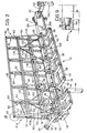
- a collapsible plate holder which, in Figure 2 is designated as a whole by 34 and is shown in the deployed state of service for transporting plates.
- the easel 34 consists essentially of metal sections connected in the manner which will be described later.
- the easel 34 has in cross section a trapezoidal shape suitable for defining two inclined support and fixing faces for plates L, for example glass plates (FIGS. 5 to 8).
- the easel comprises inter alia a base frame 35, the main elements of which are a robust box-shaped center beam 36 and cross-members 38 which protrude on each side of the beam 36 and whose projecting ends are connected by bars 40 which constitute the longitudinal side edges of the base frame 35.
- the protrusions of the crosspieces 14 carry inclined bars 42 for the support of the lower edges of the plates to be transported.
- the bridge 34 shown comprises, towards an anterior end relative to the direction of travel of the vehicle, a pair of retractable support legs 44 whose upper ends are wedged on a rotary transverse axis 46 to allow oscillation between a position vertical working and, as in Figure 2, and a folded back position horizontally.
- the legs 44 are returned to the vertical working position by a common spring 48 which acts on a crank arm 50 fixed on the axis 46.
- the rear end 36 a of the longitudinal beam 36 carries a cross member 52 with a pair of telescopically retractable legs 54.
- the beam 36 carries a crosspiece 56 located further forward of the legs 44 and at the ends of which are rotatably mounted side wheels 58 with transverse axis whose function will be explained later.
- rings 60 are at the two ends of the easel 34 for the emergency lifting or for loading and unloading from vehicles other than that shown in FIG. 1.
- the two flanges 16 are provided with upper beds 66 which surmount the wheels 18 and 20.
- the beds 66 are formed by sheet metal structures in which wooden boards 68 are fitted.
- each flower bed 66 adjacent to the channel 14 has two consecutive lowered areas 70 and 71.
- the lowered areas 70 serve as support for the removable transverse wooden boards 72 which, with the longitudinal boards 68 are intended to constitute a wide load plan for general merchandise when the channel 12 is not used to transport the easel 34 in the deployed state of FIG. 2.
- the load plan can be fitted on its perimeter, at the outer limit of the vehicle, with folding load stop edges (not shown). There is also provision for covering the load (easel 34 or miscellaneous goods) with a removable tarpaulin that can be adjusted in height (not shown).
- the still lowered zones 71 constitute tracks for the rolling of the wheels 58 (FIG. 2) of the structure 34.
- the arrangement is such that the wheels resting on the tracks 71 do not protrude above the level of the bearing zones 70 planks.
- Each track 71 has, at the rear end of the channel 12, a respective part 73 inclined as a ramp to facilitate the engagement of the wheels 58 and cause an initial lifting of the front part of the structure 34.
- the load plane 14 of the channel 12 is delimited at the rear by an edge constituted by a robust cross member 74.
- the flanges 16 are provided with converging cheeks 76 to favor the centering of the structure 34 when inserting the latter in the channel 12 as will now be described with reference to FIGS. 5 to 8.
- the bridge rests on the ground by means of its folding front legs 44 and of its telescopic rear legs. 54.
- the semi-trailer 10 moves back.
- the air suspensions have been unloaded so that the load plane 14 is at the minimum level.
- the roller 62 of the plane 14 is at a level lower than that of the underside of the base frame 35 of the easel 34.
- the tracks 70 of the flanges 16 are at a level slightly lower than that wheels 58.
- the rear part of the channel 12 frames the front part of the bridge 34 (FIG. 6).
- the front parts of the longitudinal members 36 surmount the roller 62 and the wheels 58 slightly overcome the tracks 71, or else have risen, with the whole front part of the trestle 34, thanks to the rise of the wheels 58 along the ramps 73.
- At least one of the flanges 16 is provided with a stop block 78 which constitutes an obstacle towards the rear end of the corresponding track 71.
- a stop block 78 which constitutes an obstacle towards the rear end of the corresponding track 71.
- the telescopic legs 54 are contracted after a further lifting of the rear part of the vehicle has been carried out, by means of the valve 52, as illustrated in FIG. 8.
- the bridge 34 is then blocked in the channel 12, using means not shown, the stop block 78 is replaced and, finally, the suspensions are deflated by acting on the control valve 22 until bringing the load plan 14 and the entire channel 12 at the normal running level of the vehicle.
- the unloading operation occurs with a reverse sequence to that described above. It should be noted that, thanks to the presence of the stop block 78, when the semi-trailer 10 is released from the structure 34 by an amount such that one of the wheels 58 strikes the block 78, the legs 44 which are already protruding beyond the edge 74 of the load plane 14 have already been brought back to the vertical working position by the return spring 48 (FIG. 2).
- the operator must remove the block 78 and, at the same time, operate the control valve 32 so as to obtain the lowering of the load plane 14 to the minimum level and support the bridge 34 on its four legs. It is only under these conditions that the arrangement of the semi-trailer 10 can continue until the bridge 34 is finally abandoned.
- Each ordinate 80, 80a comprises a pair of uprights indicated respectively at 82 and 82a. These uprights converge upwards in an isosceles triangle configuration, so as to define, on both sides of the bridge 34, respective bearing faces for the plates, in a known manner.
- each ordinate 80, 80a the two uprights 82 and 82a are connected, at intervals, by stiffening crosspieces 84.
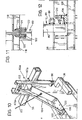
- Each of the ordinates 84 is articulated at the bottom on the beam 36 along a transverse axis materialized by a pin 86.
- a ridge beam 88 to which the ordinates 90 are likewise articulated along transverse axes materialized by pins 90.
- the top or the top of the ordinate 80a is provided with a doulle 92.
- the sleeve 92 has a conical hole 94 in which is engaged a conical pin 96 of the corresponding end of the beam of ridge 88.
- the additional end ordinate 80a is articulated at the bottom at the corresponding end of the beam 36, of analogously to the ordinates 80, using a transverse dowel 98.
- an arrow 104 whose lower end has a transverse eye 106.
- the eye 106 is located between the ears 100.
- a removable pin 100 is threaded through which the arrow 104 provides for blocking the ordinate 80a in the erected state.
- a winch 110 behind the cross member 56 and on the beam 36 is mounted a winch 110.
- the latter has been shown to be manually operated but it could also advantageously be operated electrically, hydraulically, pneumatically, etc.
- a metal cord 112 wound on the winch drum 110 is returned on a pulley 114 carried by the uprights 82a of the ordinate 80a towards their top and is anchored to the ordinate 80 adjacent to a point 116 located at a level also close to the top of this ordinate.
- the rope 112 in tension in the arrangement of FIG. 2, keeps all the other ordinates 80 upright. and keeps the pin 96 of the ridge beam 88 engaged in the socket 92.
- the uprights 80, 80a of the consecutive ordinates are connected by small removable horizontal frames 118.
- each of these small frames 118 is provided, at each of its ends with a corresponding tongue 120.
- the tongues 120 are engaged from top to bottom in corresponding pockets 122 carried by the crosspieces 84 of the ordinates 80 and 80a.
- each upright 82 of the ordinates 80 is provided (FIG. 12), below its axis of articulation on the beam 36, with a pin respective conical 124, engaged horizontally in a corresponding conical sleeve 126 fixed to a sill 128 which is part of the base frame and runs along the side of the central beam 36.
- the arrangement of pins 124 in the sockets 126 in particular prevents possible lateral movements of the uprights 80 due to sliding of their axes 86.
- the tie rods 130 are detachably anchored to the beam 36 as well as, at the top, to the respective ordinates 80 (the second and the penultimate starting from the left in FIG. 2).
- the same tie rods 130 are fitted with screw tensioners 134.
- the easel 34 can be made to move from the upright service arrangement of FIG. 2 to a collapsed or folded arrangement, for its piling up in the channel 12 of the vehicle 10 in FIG.
- the small chassis 118 are removed by releasing their tongues 120 from the pockets 122 and then the tie rods 130 (those on the left in FIG. 2) are released.
- the winch drum 110 which has an appropriate reduction gear, the rope 112 is unwound from the drum and the ordinates 80 fall or swing to the right, as indicated by the arrow A in FIG. 13.
- the pins 96 and 120 emerge from the respective sockets 92 and 126.
- the movements of the ordinates 80 and of the ridge beam 88 occur as the movements of three consecutive sides of an articulated parallelogram, the fourth side of which is constituted by the transverse beam 36 of the base frame.
- the ordinates 80 and 80a occupy a “flattened” arrangement substantially horizontal on the beam 36 of the base frame 35.
- the ordinates are embedded in one another , the ordinate 30 situated at the rear end of the easel 34 (on the right in FIGS. 13 and 14), in the state of FIG. 14, rests on the terminal part or "tail" 36a of the beam 36, with interposition of a block or cushion 136 (also visible in FIG. 2).
- the chevatet 34 can also be folded up and deployed while it is on the vehicle 10 in the state of FIG. 8.
Landscapes
- Engineering & Computer Science (AREA)
- Health & Medical Sciences (AREA)
- Public Health (AREA)
- Transportation (AREA)
- Mechanical Engineering (AREA)
- Handcart (AREA)
Claims (13)
Priority Applications (1)
| Application Number | Priority Date | Filing Date | Title |
|---|---|---|---|
| AT81830242T ATE11658T1 (de) | 1980-12-09 | 1981-12-03 | Aus einem strassentransportfahrzeug und einem abnehmbaren bockgestell bestehende anordnung fuer den transport von plattenfoermigem material. |
Applications Claiming Priority (4)
| Application Number | Priority Date | Filing Date | Title |
|---|---|---|---|
| IT6886980 | 1980-12-09 | ||
| IT68869/80A IT1129938B (it) | 1980-12-09 | 1980-12-09 | Gruppo comprendente un veicolo stradale da trasporto particolarmente un semirimorchio ed una struttura portacarico amovible particolarmente un cavalletto per il trasporto di lastre |
| ITTO1981U53233U IT8153233U1 (it) | 1981-05-14 | 1981-05-14 | Cavalletto ripiegabile per il trasporto di lastre |
| IT5323381U | 1981-05-14 |
Publications (2)
| Publication Number | Publication Date |
|---|---|
| EP0054008A1 EP0054008A1 (de) | 1982-06-16 |
| EP0054008B1 true EP0054008B1 (de) | 1985-02-06 |
Family
ID=26329555
Family Applications (1)
| Application Number | Title | Priority Date | Filing Date |
|---|---|---|---|
| EP19810830242 Expired EP0054008B1 (de) | 1980-12-09 | 1981-12-03 | Aus einem Strassentransportfahrzeug und einem abnehmbaren Bockgestell bestehende Anordnung für den Transport von Plattenförmigem Material |
Country Status (2)
| Country | Link |
|---|---|
| EP (1) | EP0054008B1 (de) |
| DE (1) | DE3168836D1 (de) |
Cited By (1)
| Publication number | Priority date | Publication date | Assignee | Title |
|---|---|---|---|---|
| DE102008032182A1 (de) | 2008-07-09 | 2010-04-22 | Ozv Gmbh & Co. Kg | Transportaufleger für unteilbare Lasten mit eigener Be- und Entladung |
Families Citing this family (9)
| Publication number | Priority date | Publication date | Assignee | Title |
|---|---|---|---|---|
| DE3438679A1 (de) * | 1984-10-22 | 1987-02-12 | Ulrich Loch | Innenlader-sattelzug |
| DE3507587A1 (de) * | 1985-03-04 | 1986-09-04 | Fahrzeugbau Langendorf GmbH & Co KG, 4355 Waltrop | Als auflieger einer sattelzugmaschine ausgebildeter innenlader fuer den strassenverkehr von transportgestellen, insbesondere fuer den flachglastransport |
| EP2042369B1 (de) * | 2005-07-21 | 2016-03-23 | Van Huët Glastransport B.V. | Transportvorrichtung |
| BRMU9100176U2 (pt) * | 2011-02-08 | 2014-02-25 | Heberson Cosso | Sistema de multi-uso em semi-reboque de suspensão independente e sem viga de eixo |
| ES2457965B1 (es) * | 2014-03-17 | 2015-02-11 | Centre Luxembourgeois De Recherches Pour Le Verre Et La Ceramique, S.A.R.L. | Conjunto de vehículo góndola y caballete para transporte de vidrio |
| JP2019516627A (ja) * | 2015-12-28 | 2019-06-20 | ローゼンフェルド,イェヒエル | 細長い材料を運搬及び収容するためのシステム |
| DE102017105563B4 (de) | 2017-03-15 | 2021-03-04 | Faymonville Distribution Ag | Innenladerglasgestell |
| MX2020011603A (es) | 2020-10-30 | 2022-05-02 | Cruz Ungson Daniel Santa | Caballete desplegable para carga y transporte de vidrio plano. |
| CN115871728B (zh) * | 2022-11-29 | 2025-06-24 | 中车沈阳机车车辆有限公司 | 一种滚道梁托架及锁止一体式立柱 |
Family Cites Families (11)
| Publication number | Priority date | Publication date | Assignee | Title |
|---|---|---|---|---|
| FR1323104A (fr) * | 1962-04-02 | 1963-04-05 | Proleride Transp Systems | Plate-forme de camion avec récipient amovible et transportable |
| FR1516897A (fr) * | 1966-12-30 | 1968-02-05 | Ackermann Fahrzeugbau Fa | Perfectionnements apporté à la manipulation des containers |
| FR1541937A (fr) * | 1967-10-26 | 1968-10-11 | Véhicule de transport avec plateau de chargement interchangeable | |
| FR1585958A (de) * | 1968-07-22 | 1970-02-06 | ||
| DE2050251A1 (de) * | 1970-10-13 | 1972-04-20 | Sauer, Roman Franz, 8752 Keilberg | Vorrichtung zum Anheben des Chassis von Fahrzeugen mit Blattfederung |
| US3738517A (en) * | 1972-03-27 | 1973-06-12 | J Luse | Pickup camper loading arrangement |
| DE2307430C3 (de) * | 1973-02-15 | 1979-01-04 | Peter Bauer Gmbh & Co Kg, 5000 Koeln | Sattelanhänger für Sattelzüge mit üblichen Zugmaschinen |
| US3848917A (en) * | 1973-04-09 | 1974-11-19 | Neal J O | Apparatus for transporting flat glass and the like |
| DE2653278A1 (de) * | 1976-11-24 | 1978-06-01 | Langendorf Fahrzeugbau | Tieflader, insbesondere auflieger fuer den strassentransport von sperrigen lasten, z.b. von glasscheiben in aufrechter stellung |
| US4273485A (en) * | 1978-08-07 | 1981-06-16 | Ppg Industries, Inc. | Semi-trailer shipping support structure |
| GB2031387A (en) * | 1978-10-17 | 1980-04-23 | Fruehauf Crane Ltd | Cross-lock for Demountable Body Systems |
-
1981
- 1981-12-03 EP EP19810830242 patent/EP0054008B1/de not_active Expired
- 1981-12-03 DE DE8181830242T patent/DE3168836D1/de not_active Expired
Cited By (1)
| Publication number | Priority date | Publication date | Assignee | Title |
|---|---|---|---|---|
| DE102008032182A1 (de) | 2008-07-09 | 2010-04-22 | Ozv Gmbh & Co. Kg | Transportaufleger für unteilbare Lasten mit eigener Be- und Entladung |
Also Published As
| Publication number | Publication date |
|---|---|
| DE3168836D1 (en) | 1985-03-21 |
| EP0054008A1 (de) | 1982-06-16 |
Similar Documents
| Publication | Publication Date | Title |
|---|---|---|
| EP3400183B1 (de) | Palette mit nestbarer doppelstöckiger ladestruktur | |
| EP3645365B1 (de) | Verfahren zum laden/entladen eines sattelaufliegers auf einem taschenwagen und dafür geeigneter taschenwagen | |
| EP3174757B1 (de) | Individuelle, universelle, entfernbare, lasttragende palette für autotragefahrzeug | |
| EP0054008A1 (de) | Aus einem Strassentransportfahrzeug und einem abnehmbaren Bockgestell bestehende Anordnung für den Transport von Plattenförmigem Material | |
| FR2687654A1 (fr) | Structure pour permettre de charger ou decharger des marchandises a transporter avec un dispositif de manutention a bras de levage hydraulique. | |
| EP0586318B1 (de) | Umstellbarer, doppelter Boden für Kraftfahrzeuge in einer Transporteinheit | |
| EP0634981B1 (de) | Einziehbare einrichtung zum bedecken und öffnen eines zwei-oder dreidimensionalen platzes | |
| FR2686843A1 (fr) | Ensemble basculant-coulissant de chargement par traction a partir du sol et de transport, pour porteur routier. | |
| FR2470705A1 (fr) | Dispositif pour deposer une charge sur le sol a partir d'un camion, et inversement, et son procede d'utilisation | |
| FR2535659A1 (fr) | Vehicule routier avec superstructure porte-charge amovible particulierement superstructure porte-vehicules | |
| FR2522597A1 (fr) | Appareil pour la manutention de charges | |
| EP0799789A1 (de) | Vorrichtung zum Befestigen eines Gabelstaplers auf einem Lastkraftwagen, Halterahmen und Lastkraftwagen dafür | |
| EP0096133A1 (de) | Hubportal zum senkrechten Handhaben von Lasten | |
| EP0809600B1 (de) | Lastaufnahme-fahrzeug | |
| EP0070944A1 (de) | Sattelanhänger für den Transport von Glashalteböcken od. dgl. mit unabhängiger Be- und Entladung und Verfahren zur Durchführung | |
| FR2540050A1 (fr) | Vehicule a moteur comportant un plateau elevateur de charge | |
| EP1827904A1 (de) | Mobiler querträger zur abstützung und übergabe zum laden und entladen einer last auf einem anhänger von einem mit einem lasthandhabungsarm versehenen lastwagen | |
| EP0064426B1 (de) | Halbautomatische Waggonbeladeeinrichtung | |
| WO2021053274A1 (fr) | Dispositif pour la mise à l'eau d'un objet flottant à partir d'un véhicule, et véhicule associé | |
| FR2831862A1 (fr) | Leve conteneur | |
| FR2458423A1 (fr) | Materiel de transport de conteneurs, notamment de conteneurs normalises | |
| FR2634441A1 (fr) | Chariot d'achat de type emboitable | |
| WO2010091987A1 (fr) | Monte-meuble et procédé de transport de charges | |
| EP0344080A1 (de) | Anhängewagen für Kraftwagen, bestimmt für den Transport eines Kegelspiels | |
| FR2556705A1 (fr) | Appareil de levage pour vehicules roulants ou autres |
Legal Events
| Date | Code | Title | Description |
|---|---|---|---|
| PUAI | Public reference made under article 153(3) epc to a published international application that has entered the european phase |
Free format text: ORIGINAL CODE: 0009012 |
|
| AK | Designated contracting states |
Designated state(s): AT BE CH DE FR GB LU NL SE |
|
| TCAT | At: translation of patent claims filed | ||
| TCNL | Nl: translation of patent claims filed | ||
| 17P | Request for examination filed |
Effective date: 19821001 |
|
| DET | De: translation of patent claims | ||
| GRAA | (expected) grant |
Free format text: ORIGINAL CODE: 0009210 |
|
| AK | Designated contracting states |
Designated state(s): AT BE CH DE FR GB LI LU NL SE |
|
| REF | Corresponds to: |
Ref document number: 11658 Country of ref document: AT Date of ref document: 19850215 Kind code of ref document: T |
|
| REF | Corresponds to: |
Ref document number: 3168836 Country of ref document: DE Date of ref document: 19850321 |
|
| PG25 | Lapsed in a contracting state [announced via postgrant information from national office to epo] |
Ref country code: AT Effective date: 19851203 |
|
| PG25 | Lapsed in a contracting state [announced via postgrant information from national office to epo] |
Ref country code: SE Effective date: 19851204 |
|
| PLBE | No opposition filed within time limit |
Free format text: ORIGINAL CODE: 0009261 |
|
| STAA | Information on the status of an ep patent application or granted ep patent |
Free format text: STATUS: NO OPPOSITION FILED WITHIN TIME LIMIT |
|
| PG25 | Lapsed in a contracting state [announced via postgrant information from national office to epo] |
Ref country code: LU Free format text: LAPSE BECAUSE OF NON-PAYMENT OF DUE FEES Effective date: 19851231 Ref country code: LI Effective date: 19851231 Ref country code: CH Effective date: 19851231 Ref country code: BE Effective date: 19851231 |
|
| 26N | No opposition filed | ||
| BERE | Be: lapsed |
Owner name: ROLFO S.P.A. Effective date: 19851231 |
|
| PG25 | Lapsed in a contracting state [announced via postgrant information from national office to epo] |
Ref country code: NL Effective date: 19860701 |
|
| GBPC | Gb: european patent ceased through non-payment of renewal fee | ||
| NLV4 | Nl: lapsed or anulled due to non-payment of the annual fee | ||
| PG25 | Lapsed in a contracting state [announced via postgrant information from national office to epo] |
Ref country code: FR Free format text: LAPSE BECAUSE OF NON-PAYMENT OF DUE FEES Effective date: 19860829 |
|
| REG | Reference to a national code |
Ref country code: CH Ref legal event code: PL |
|
| PG25 | Lapsed in a contracting state [announced via postgrant information from national office to epo] |
Ref country code: DE Effective date: 19860902 |
|
| REG | Reference to a national code |
Ref country code: FR Ref legal event code: ST |
|
| PG25 | Lapsed in a contracting state [announced via postgrant information from national office to epo] |
Ref country code: GB Effective date: 19881118 |
|
| EUG | Se: european patent has lapsed |
Ref document number: 81830242.4 Effective date: 19860902 |