EP0054021B1 - Drehbare biologische berührungsvorrichtung - Google Patents
Drehbare biologische berührungsvorrichtung Download PDFInfo
- Publication number
- EP0054021B1 EP0054021B1 EP19800900952 EP80900952A EP0054021B1 EP 0054021 B1 EP0054021 B1 EP 0054021B1 EP 19800900952 EP19800900952 EP 19800900952 EP 80900952 A EP80900952 A EP 80900952A EP 0054021 B1 EP0054021 B1 EP 0054021B1
- Authority
- EP
- European Patent Office
- Prior art keywords
- segments
- rbc
- shaft
- members
- rotating biological
- Prior art date
- Legal status (The legal status is an assumption and is not a legal conclusion. Google has not performed a legal analysis and makes no representation as to the accuracy of the status listed.)
- Expired
Links
- 238000003825 pressing Methods 0.000 claims abstract description 3
- XLYOFNOQVPJJNP-UHFFFAOYSA-N water Substances O XLYOFNOQVPJJNP-UHFFFAOYSA-N 0.000 claims description 11
- QVGXLLKOCUKJST-UHFFFAOYSA-N atomic oxygen Chemical group [O] QVGXLLKOCUKJST-UHFFFAOYSA-N 0.000 claims description 4
- 229910052760 oxygen Inorganic materials 0.000 claims description 4
- 239000001301 oxygen Substances 0.000 claims description 4
- 230000002093 peripheral effect Effects 0.000 claims description 3
- 239000010802 sludge Substances 0.000 abstract description 5
- 238000013461 design Methods 0.000 abstract description 3
- 239000000463 material Substances 0.000 description 8
- 238000010276 construction Methods 0.000 description 2
- 238000000034 method Methods 0.000 description 2
- 239000002351 wastewater Substances 0.000 description 2
- 238000005260 corrosion Methods 0.000 description 1
- 230000007797 corrosion Effects 0.000 description 1
- 238000005336 cracking Methods 0.000 description 1
- 238000005520 cutting process Methods 0.000 description 1
- 238000011161 development Methods 0.000 description 1
- 230000018109 developmental process Effects 0.000 description 1
- 238000005188 flotation Methods 0.000 description 1
- 238000003780 insertion Methods 0.000 description 1
- 230000037431 insertion Effects 0.000 description 1
- 238000004519 manufacturing process Methods 0.000 description 1
- 238000012856 packing Methods 0.000 description 1
- 238000004062 sedimentation Methods 0.000 description 1
Images

Classifications
-
- C—CHEMISTRY; METALLURGY
- C02—TREATMENT OF WATER, WASTE WATER, SEWAGE, OR SLUDGE
- C02F—TREATMENT OF WATER, WASTE WATER, SEWAGE, OR SLUDGE
- C02F3/00—Biological treatment of water, waste water, or sewage
- C02F3/02—Aerobic processes
- C02F3/08—Aerobic processes using moving contact bodies
- C02F3/082—Rotating biological contactors
-
- Y—GENERAL TAGGING OF NEW TECHNOLOGICAL DEVELOPMENTS; GENERAL TAGGING OF CROSS-SECTIONAL TECHNOLOGIES SPANNING OVER SEVERAL SECTIONS OF THE IPC; TECHNICAL SUBJECTS COVERED BY FORMER USPC CROSS-REFERENCE ART COLLECTIONS [XRACs] AND DIGESTS
- Y02—TECHNOLOGIES OR APPLICATIONS FOR MITIGATION OR ADAPTATION AGAINST CLIMATE CHANGE
- Y02W—CLIMATE CHANGE MITIGATION TECHNOLOGIES RELATED TO WASTEWATER TREATMENT OR WASTE MANAGEMENT
- Y02W10/00—Technologies for wastewater treatment
- Y02W10/10—Biological treatment of water, waste water, or sewage
Definitions
- the invention relates to an improvement in Rotating Biological Contactor (RBC) process and design.
- RBC Rotating Biological Contactor
- This RBC is a biological treatment unit of the kind that comprises several segment-like RBC material bodies, which together with a supporting structure are assembled to form an RBC rotor. Waste water to be treated flows through a tank, in which the RBC rotor is immersed.
- These RBC's are in general arranged so that waste water can penetrate radially and circumferentially into the rotor and consequently the flow to and from the rotor is essentially perpendicular to the axis of the rotor.
- a rotating biological contactor comprising a rotor constituted by a shaft and by filter body segments allowing radial and peripheral water flow, wherein said filter body segments are arranged peripherally about the shaft and are radially pressed inwards towards the shaft and against each other by members extending axially of the shaft over the axial dimension of the segments and the segments are essentially triangular in their cross section resulting in a saw-tooth rotor periphery, characterized in that the filter body segments do not extend fully to the shaft but leave an open space in the proximity of the centre of the rotor, resulting in improved water flow and oxygen exchange in order to avoid anaerobic conditions therein.
- levers are used together with the members in order to obtain the necessary pressure against the filter body segments. Locking as well as location of the levers can be accomplished with the aid of pins, thus avoiding problems with corrosion of screws and bolts, and simplifying readjustment of the segments, but, of course, bolts can be used also in order to secure the V-shaped members at a pressure transferring location.
- an RBC having filter body segments held against radial support struts by means of longitudinally extending L-shaped members. These segments may be essentially triangular and mounted about the shaft to give a saw-tooth peripheral form.
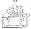
- fig. 1 shows an RBC in accordance with the invention seen from one end or axially submerged in a tank
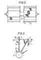
- fig. 2 an elevated view of the RBC of fig. 1, fig. 3 examples of fastening mechanism for the segments and fig. 4 and 5, on a large scale, one fastening method.
- the RBC is shown submerged in a tank 11 in which the water level 12 has been indicated.
- the rotor is intended to rotate counter-clockwise in order to give a certain turbulence close to the bottom of the tank in order to avoid sedimentation there.
- a further object that is achieved is that, on rotation of the RBC, the water is propelled into the segments. This is the result of the segments having a more triangular than segmental shape. This also has advantages in connection with packing, storing and transportation of the segments prior to assembly. As can be seen from fig. 3 the segments do not extend fully to the shaft 2 of the RBC. The space between the shaft 2 and the RBC material segments 3 improves water transportation and the dislodging of sludge.
- the RBC segments 3 prevents the RBC segments 3 from being subjected to cracking pressure from the shaft. Instead the segments 3 are pressed inwards against radial spokes 1 that have a "T" cross-section. In order to improve the guiding of the spokes these may further be provided with flat members for increasing the supporting surface of the spokes and, of course, the T-shaped spokes may be exchanged for flat ones provided with flat members to give the segments their angular guidance. In the above manner the RBC segments are subjected to forces in such a way that they stand well.
- the RBC segments 3 are pressed inwards and in fig. 2-5 two ways of doing this are indicated.
- fig. 4 the pressure radially inwards on the RBC section 3 is exerted by an elongate member 5 that has a "V"- shaped cross-section and that extends between two spokes spaced axially along the RBC.
- This "V"-shaped member 5 may be perforated in one way or the other in order to allow water to stream through it.
- a lever 6 (fig. 4 and 5) extends through a hole in the spoke 1 and after the insertion of the ends of the lever 6, which has a middle part that extends over the length of the "V"-shaped member 5, this is pressed downwards towards the "V"-shaped member thus pressing it securely against the RBC segments 3.
- a bolt 13 together with the clamping means 14 securely holds the lever against the V-shaped elongate member 5.
- the spokes may be provided with several holes as has been indicated at 15 in fig. 4, in order to allow for adjustment when after some time the RBC segments have become compressed.
- the inner ends of the segments are preferably cut parallel to the outer sides. This also diminishes the risk of anaerobic conditions in the center of the RBC and also improves the abovementioned optimum material use on fabrication of the segments.
- the "V"-shaped members 17 are fastened at their ends in side plates 18 that are slidable radially along the spokes.
- the spokes and/or the sideplates 18 can be provided with elongate holes or with several holes to allow for different locking positions.
- Fastening may in the first case be by means of bolts and in the second by means of bolts or, in one way or the other, locked pins.
- the side plates may be joined by a further member with the purpose . of directing the waterflow in through the RBC segments.
- levers can, of course, be used in the same way as in fig. 4 and 5 but it is also possible only to use the levers on mounting and dismounting of the RBC segments and having the position locked by the means of pins or bolts.
- the invention results in a far more useful and economic RBC rotor than those previously used.
Landscapes
- Life Sciences & Earth Sciences (AREA)
- Engineering & Computer Science (AREA)
- Molecular Biology (AREA)
- Biodiversity & Conservation Biology (AREA)
- Microbiology (AREA)
- Hydrology & Water Resources (AREA)
- Health & Medical Sciences (AREA)
- Environmental & Geological Engineering (AREA)
- Water Supply & Treatment (AREA)
- Chemical & Material Sciences (AREA)
- Organic Chemistry (AREA)
- Biological Treatment Of Waste Water (AREA)
- Crushing And Grinding (AREA)
Claims (5)
Priority Applications (1)
| Application Number | Priority Date | Filing Date | Title |
|---|---|---|---|
| AT80900952T ATE15790T1 (de) | 1980-05-05 | 1980-05-05 | Drehbare biologische beruehrungsvorrichtung. |
Applications Claiming Priority (1)
| Application Number | Priority Date | Filing Date | Title |
|---|---|---|---|
| PCT/SE1980/000129 WO1981002730A1 (en) | 1980-05-05 | 1980-05-05 | Rotating biological confactor |
Publications (2)
| Publication Number | Publication Date |
|---|---|
| EP0054021A1 EP0054021A1 (de) | 1982-06-23 |
| EP0054021B1 true EP0054021B1 (de) | 1985-09-25 |
Family
ID=20339911
Family Applications (1)
| Application Number | Title | Priority Date | Filing Date |
|---|---|---|---|
| EP19800900952 Expired EP0054021B1 (de) | 1980-05-05 | 1980-05-05 | Drehbare biologische berührungsvorrichtung |
Country Status (4)
| Country | Link |
|---|---|
| EP (1) | EP0054021B1 (de) |
| AT (1) | ATE15790T1 (de) |
| DE (1) | DE3071113D1 (de) |
| WO (1) | WO1981002730A1 (de) |
Families Citing this family (2)
| Publication number | Priority date | Publication date | Assignee | Title |
|---|---|---|---|---|
| HRP931031B1 (en) * | 1993-07-07 | 1999-08-31 | Drum with discs for the waste waters purifier | |
| US6783669B1 (en) * | 2000-03-10 | 2004-08-31 | Sekisui Aqua Systems Co., Ltd. | Rotating disk type sewage treatment device |
Citations (5)
| Publication number | Priority date | Publication date | Assignee | Title |
|---|---|---|---|---|
| US3777891A (en) * | 1971-05-18 | 1973-12-11 | J Stengelin | Trickling filter plant |
| US3886074A (en) * | 1973-06-15 | 1975-05-27 | Autotrol Corp | Air driven rotating biological contactor apparatus |
| US3904525A (en) * | 1973-08-23 | 1975-09-09 | Lawrence R Rosenberg | Waste treatment apparatus |
| DE2554757B2 (de) * | 1974-12-12 | 1977-12-22 | Asahi Engineering Co, Ltd, Osaka (Japan) | Tauchkoerper fuer die biologische abwasserreinigung |
| US4149972A (en) * | 1977-02-16 | 1979-04-17 | Sekisui Kagaku Kogyo Kabushiki Kaisha | Waste water treating apparatus |
Family Cites Families (2)
| Publication number | Priority date | Publication date | Assignee | Title |
|---|---|---|---|---|
| US3984672A (en) * | 1974-12-05 | 1976-10-05 | Control Systems Research, Inc. | Solid state translator |
| US4099245A (en) * | 1977-05-05 | 1978-07-04 | Lockheed Electronics Co., Inc. | Transducer signalling apparatus |
-
1980
- 1980-05-05 AT AT80900952T patent/ATE15790T1/de not_active IP Right Cessation
- 1980-05-05 WO PCT/SE1980/000129 patent/WO1981002730A1/en not_active Ceased
- 1980-05-05 DE DE8080900952T patent/DE3071113D1/de not_active Expired
- 1980-05-05 EP EP19800900952 patent/EP0054021B1/de not_active Expired
Patent Citations (5)
| Publication number | Priority date | Publication date | Assignee | Title |
|---|---|---|---|---|
| US3777891A (en) * | 1971-05-18 | 1973-12-11 | J Stengelin | Trickling filter plant |
| US3886074A (en) * | 1973-06-15 | 1975-05-27 | Autotrol Corp | Air driven rotating biological contactor apparatus |
| US3904525A (en) * | 1973-08-23 | 1975-09-09 | Lawrence R Rosenberg | Waste treatment apparatus |
| DE2554757B2 (de) * | 1974-12-12 | 1977-12-22 | Asahi Engineering Co, Ltd, Osaka (Japan) | Tauchkoerper fuer die biologische abwasserreinigung |
| US4149972A (en) * | 1977-02-16 | 1979-04-17 | Sekisui Kagaku Kogyo Kabushiki Kaisha | Waste water treating apparatus |
Also Published As
| Publication number | Publication date |
|---|---|
| ATE15790T1 (de) | 1985-10-15 |
| DE3071113D1 (en) | 1985-10-31 |
| WO1981002730A1 (en) | 1981-10-01 |
| EP0054021A1 (de) | 1982-06-23 |
Similar Documents
| Publication | Publication Date | Title |
|---|---|---|
| US4631974A (en) | Polymeric split sprocket wheel | |
| US4668387A (en) | Deep submergence rotating biological contactor apparatus | |
| US4720207A (en) | Segmented rotor | |
| US3904525A (en) | Waste treatment apparatus | |
| US5165522A (en) | Collector flight attachment link for collector apparatus | |
| US4150921A (en) | Built-up marine propellers with adjustable pitch and axially removable blades | |
| US4006855A (en) | Separator worm feed auger and wear plates | |
| US5035681A (en) | Reduced friction sprocket assembly for use in corrosive environments | |
| EP0054021B1 (de) | Drehbare biologische berührungsvorrichtung | |
| US4256580A (en) | Waste water purifying plant | |
| US4385987A (en) | Water treatment apparatus | |
| US3317254A (en) | Demountable marine bearing | |
| JP2023130767A (ja) | レール走行式機器、レール走行式掻寄機、及びレール走行式掻取機の蛇行補正・脱輪防止装置及び方法 | |
| DE2340584A1 (de) | Tauchtropfkoerperanlage | |
| KR100713774B1 (ko) | 저류조의 슬러지 침전방지용 임펠러 | |
| US6279752B1 (en) | Wide rectangular clarifiers | |
| US3327861A (en) | Strainer | |
| AU621423B2 (en) | Reduced friction spool bearing and method of making same | |
| US4708590A (en) | Cover for turbines and pumps | |
| EP1473078B1 (de) | Biogasanlagen-Tauchmotorrührgerät | |
| DE10218443B4 (de) | Segmentkranz-Wasserrad | |
| US5131890A (en) | Reduced friction spool bearing and method of making same | |
| CA1036507A (en) | Traction-driven composite sludge raking mechanism for sedimentation tanks | |
| KR102678474B1 (ko) | 드럼스크린 | |
| KR102220136B1 (ko) | 분리형 구동부를 갖는 원형 슬러지 수집기 |
Legal Events
| Date | Code | Title | Description |
|---|---|---|---|
| PUAI | Public reference made under article 153(3) epc to a published international application that has entered the european phase |
Free format text: ORIGINAL CODE: 0009012 |
|
| 17P | Request for examination filed |
Effective date: 19810720 |
|
| AK | Designated contracting states |
Kind code of ref document: A1 Designated state(s): AT CH DE FR GB LI LU NL SE |
|
| RAP1 | Party data changed (applicant data changed or rights of an application transferred) |
Owner name: NOVATEC AB |
|
| RAP1 | Party data changed (applicant data changed or rights of an application transferred) |
Owner name: NOVATEK AB |
|
| GRAA | (expected) grant |
Free format text: ORIGINAL CODE: 0009210 |
|
| AK | Designated contracting states |
Kind code of ref document: B1 Designated state(s): AT CH DE FR GB LI LU NL SE Designated state(s): AT CH DE FR GB LI LU NL SE |
|
| PG25 | Lapsed in a contracting state [announced via postgrant information from national office to epo] |
Ref country code: NL Effective date: 19850925 Ref country code: LI Effective date: 19850925 Ref country code: FR Free format text: THE PATENT HAS BEEN ANNULLED BY A DECISION OF A NATIONAL AUTHORITY Effective date: 19850925 Ref country code: CH Effective date: 19850925 Ref country code: AT Effective date: 19850925 |
|
| REF | Corresponds to: |
Ref document number: 15790 Country of ref document: AT Date of ref document: 19851015 Kind code of ref document: T |
|
| REF | Corresponds to: |
Ref document number: 3071113 Country of ref document: DE Date of ref document: 19851031 |
|
| REG | Reference to a national code |
Ref country code: CH Ref legal event code: PL |
|
| NLV1 | Nl: lapsed or annulled due to failure to fulfill the requirements of art. 29p and 29m of the patents act | ||
| PG25 | Lapsed in a contracting state [announced via postgrant information from national office to epo] |
Ref country code: LU Free format text: LAPSE BECAUSE OF NON-PAYMENT OF DUE FEES Effective date: 19860531 |
|
| EN | Fr: translation not filed | ||
| PLBE | No opposition filed within time limit |
Free format text: ORIGINAL CODE: 0009261 |
|
| STAA | Information on the status of an ep patent application or granted ep patent |
Free format text: STATUS: NO OPPOSITION FILED WITHIN TIME LIMIT |
|
| 26N | No opposition filed | ||
| GBPC | Gb: european patent ceased through non-payment of renewal fee | ||
| PG25 | Lapsed in a contracting state [announced via postgrant information from national office to epo] |
Ref country code: DE Effective date: 19870203 |
|
| PG25 | Lapsed in a contracting state [announced via postgrant information from national office to epo] |
Ref country code: GB Effective date: 19881118 |
|
| PG25 | Lapsed in a contracting state [announced via postgrant information from national office to epo] |
Ref country code: SE Effective date: 19890506 |
|
| EUG | Se: european patent has lapsed |
Ref document number: 80900952.5 Effective date: 19900412 |