EP0054089B1 - Trommelmagazin für eine Feuerwaffe - Google Patents
Trommelmagazin für eine Feuerwaffe Download PDFInfo
- Publication number
- EP0054089B1 EP0054089B1 EP19800304480 EP80304480A EP0054089B1 EP 0054089 B1 EP0054089 B1 EP 0054089B1 EP 19800304480 EP19800304480 EP 19800304480 EP 80304480 A EP80304480 A EP 80304480A EP 0054089 B1 EP0054089 B1 EP 0054089B1
- Authority
- EP
- European Patent Office
- Prior art keywords
- cartridges
- sprocket means
- sprocket
- housing
- drum magazine
- Prior art date
- Legal status (The legal status is an assumption and is not a legal conclusion. Google has not performed a legal analysis and makes no representation as to the accuracy of the status listed.)
- Expired
Links
- 230000002093 peripheral effect Effects 0.000 claims description 8
- 230000000994 depressogenic effect Effects 0.000 claims description 7
- 239000004033 plastic Substances 0.000 claims description 5
- 229920003023 plastic Polymers 0.000 claims description 5
- 239000000463 material Substances 0.000 claims description 3
- 238000000465 moulding Methods 0.000 claims description 3
- 238000010137 moulding (plastic) Methods 0.000 claims description 2
- 230000037431 insertion Effects 0.000 description 4
- 238000003780 insertion Methods 0.000 description 4
- 230000000881 depressing effect Effects 0.000 description 2
- 238000005096 rolling process Methods 0.000 description 2
- 239000004677 Nylon Substances 0.000 description 1
- 210000000078 claw Anatomy 0.000 description 1
- 230000006835 compression Effects 0.000 description 1
- 238000007906 compression Methods 0.000 description 1
- 230000009977 dual effect Effects 0.000 description 1
- 210000005069 ears Anatomy 0.000 description 1
- 230000000694 effects Effects 0.000 description 1
- 239000002184 metal Substances 0.000 description 1
- 239000002991 molded plastic Substances 0.000 description 1
- 229920001778 nylon Polymers 0.000 description 1
- 230000000979 retarding effect Effects 0.000 description 1
- XLYOFNOQVPJJNP-UHFFFAOYSA-N water Substances O XLYOFNOQVPJJNP-UHFFFAOYSA-N 0.000 description 1
Images




Classifications
-
- F—MECHANICAL ENGINEERING; LIGHTING; HEATING; WEAPONS; BLASTING
- F41—WEAPONS
- F41A—FUNCTIONAL FEATURES OR DETAILS COMMON TO BOTH SMALLARMS AND ORDNANCE, e.g. CANNONS; MOUNTINGS FOR SMALLARMS OR ORDNANCE
- F41A9/00—Feeding or loading of ammunition; Magazines; Guiding means for the extracting of cartridges
- F41A9/61—Magazines
- F41A9/64—Magazines for unbelted ammunition
- F41A9/73—Drum magazines
-
- F—MECHANICAL ENGINEERING; LIGHTING; HEATING; WEAPONS; BLASTING
- F41—WEAPONS
- F41A—FUNCTIONAL FEATURES OR DETAILS COMMON TO BOTH SMALLARMS AND ORDNANCE, e.g. CANNONS; MOUNTINGS FOR SMALLARMS OR ORDNANCE
- F41A17/00—Safety arrangements, e.g. safeties
- F41A17/34—Magazine safeties
- F41A17/38—Magazine mountings, e.g. for locking the magazine in the gun
Definitions
- This invention relates to a drum magazine for a gun.
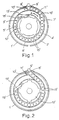
- a further known magazine is the Soumi drum magazine, described in the forementioned book at pages 562-565 and G.B. Patent No. 472,784 and shown in Figures 1 and 2 of the accompanying drawings.
- a circular, pan-like housing 1' is provided having a rotatable base plate 2' upon which the cartridges sit in paths 3', 4' defined by concentric guides 5', 6' and the inner surface of the housing 1' respectively and a bridge 7' linking the paths 3', 4'; the guides 5', 6' and bridge 7' being rotatable with the base plate 2'.
- the housing has a throat 8', a feed ramp 9' and a stop 10' with which a lug 111 mounted on the guide 5' co-operates.
- a coil spring (not shown) beneath a rotor 12' drives the rotor and an associated pivotal pusher 13'.
- the cartridges are referenced 15' and the cartridge adjacent the lug 11' is referenced 16'.
- the spring drives the rotor 12' and pusher 13' which applies pressure in the direction of arrow-headed line A, through all of the cartridges up to the lug 11' so that it is the pressure on cartridge 16' which drives the guides 5', 6' and the base plate 2'.
- the pressure on lug 11' thus urges the cartridges up the ramp 9' and through the feed throat 8'.
- the friction is - less than with the Thompson magazine because the guides 5', 6' that form the inside and outside diameter of the innermost row of ammunition moves with the ammunition for the first revolution.
- the outer row is driven out of the feed throat, but its inside diameter guide moves with it so that the outer row has only one half the sliding friction contact of the Thompson type and the inner row has non at all.
- the lug 11' engages the stop 10', the bridge 7' from the inner path 3' to the outer path 4' is in alignment with the feed throat 8' and the base plate 2' no longer rotates so that the inner row of cartridges abrade against the stationary guide surfaces, thereby producing a high friction force which is similar to that of the Thompson magazine.
- a further disadvantage of the forementioned drum magazine is that they can only readily be filled with cartridges by removing the circular planar cover, since they can only be filled through the feed throat by sliding cartridges between the feed lips in the axial direction of the housing.
- the present invention seeks to provide a drum magazine of compact dimensions and of relatively large capacity which exhibits less friction to cartridge movement than the drum magazines described above and in which cartridges may be inserted into the magazine through the feed throat in a direction perpendicular to the housing axis.
- a drum magazine for a gun including a stationary housing, an inner rotatably mounted member and an outer rotatably mounted member substantially concentric therewith, drive means for rotating the members in a first direction, stop means for limiting rotation of the outer member with respect to the housing characterised by latch means between the outer member and the housing arranged to lock when the stop means limit the rotation of the outer member to thereby prevent rotation of the outer member in a counter direction to the first direction until the inner member is rotated in said counter direction a predetermined amount.
- each said members each comprise a substantially concentric sprocket means, each said sprocket means including a tubular member and having an outer periphery provided with a plurality of serrations arranged to nest a plurality of cartridges.
- the stop means comprise abuttable stop members provided between the housing and the outermost sprocket means and between adjacent sprocket means except between the innermost sprocket means and the sprocket means adjacent thereto.
- further latch means are provided between adjacent sprocket means except between the innermost sprocket means and the sprocket means adjacent thereto, each said latch means being engageable when the cooperating stop members about each other such that each said latch means prevent rotation of an associated latched sprocket means until the serrations thereof are required to be filled with cartridges.
- the latch means between the housing and the outermost sprocket means comprise a strip member pivotally connected to the outermost sprocket means and spring biassed toward the inner peripheral wall of the housing, and a recess or aperture in said peripheral wall, the strip member having an ear for engaging with the lip of the recess or aperture when the stop members associated with the housing and the outermost sprocket means abut.
- the further latch means between adjacent sprocket means comprise a strip member pivotally connected to the inner of the two adjacent sprocket means which is spring biassed toward the inner wall of the tubular member of the adjacent outer sprocket means and a recess or aperture in said inner wall, the strip member of the further latch means having an ear for engaging with a lip of the recess or aperture in said inner wall when the stop members associated with the adjacent sprocket means abut.
- said strip member has a tang on the opposite side of the associated pivot from the ear which tang passes through the tubular member of the sprocket means to which it is attached and toward the adjacent inner sprocket means, whereby the tang is arranged to have a length sufficient to be contacted by a cartridge on said adjacent inner sprocket means for the strip member to be rotated thereby such that the ear of the strip member disengages its associated lip and permits the sprocket means to which the strip member is attached to rotate.
- the strip member is located in the wall of the tubular member of the sprocket means to which the strip member is attached and arranged to be depressed therein by cartridges on said sprocket means.
- the sprocket means each comprise the tubular member with at least two circular, radially extending flanges spaced therealong, each flange having serrations arranged to nest a plurality of cartridges therebetween, the serrations of the innermost sprocket means being spaced from the inner surface of the next adjacent outer sprocket means by substantially the same distance as the serrations of the outermost sprocket means are from the housing interior peripheral wall, a cartridge feed aperture in each tubular member except the innermost for permitting cartridges to pass through the apertured tubular members and feed ramps arranged to guide cartridges from each of the sprocket means to a feed throat of the housing.
- the strip member has a finger adjacent said ear but directed inwardly to pass through an aperture in the tubular member of the sprocket means to which said strip member is attached, said finger having a length and position such that when the strip member is depressed by cartridges it is displaced between cartridges on the inner adjacent sprocket means to rotate said adjacent sprocket means in a direction against the force of the drive means to thereby free the pressure on the cartridges in the feed ramps.
- each sprocket means is provided with the serrations directly in the outer periphery of the tubular member.
- the rotatably mounted members are concentrically arranged within the housing and the outermost member comprises a base plate and cartridge guide rails extending from said base plate which define substantially concentric cartridge paths and a bridge linking said paths.
- the inner member is a driving means which comprises a spring driven rotor, and a pivotal pusher connected to said rotor for applying force to push the cartridges around said paths.
- both members are capable of carrying cartridges and the members are sprocket means each having an outer periphery having a plurality of serrations arranged to nest a plurality of cartridges.
- the sprocket means comprise at least two circular, radially extending flanges axially spaced along a tubular member, each flange having serrations to nest a plurality of cartridges between said flanges.
- the housing is a plastic moulding which is pan-shaped and has a cover also formed by moulding plastics and conveniently a recessed track is formed in the housing and cover for locating and guiding the sprocket means.
- the sprocket means are made from a plastics material.
- said housing has a peripheral wall defining a circularly cross-sectioned interior, a cover for the housing, a feed throat extending through said wall for releasing cartridges from said housing, and at least two rotatable concentric sprocket means, the sprocket means each comprising a concentric tubular member, at least two circular, radially extending flanges spaced therealong, each flange having serrations to nest a plurality of cartridges therebetween, a cartridge feed aperture in each tubular member except the innermost for permitting cartridges to pass from the inner sprocket means to the other sprocket means, feed ramp means arranged to guide cartridges from each of the sprocket means to the feed throat, and a pusher mounted on the innermost sprocket means which is arranged to push those remaining cartridges not pushed by nested cartridges along the feed ramp means to the feed throat, wherein the pusher comprises a U-shaped member with the free ends thereof mounted on a pivot
- a last round stop actuator comprising a spring biassed member located adjacent to a limb of the pusher for travelling with said limb, whereby the spring biassed member is extended outside the housing when said pusher rod is extended toward the outer extremity of the feed throat.
- the last round stop actuator is a leaf spring having one end connected to the pivot of the pusher and the other end thereof connected to a button, whereby the button is adjacent and biassed toward the cover and protrudes therefrom when the rod is extended in the feed throat.
- the last round stop actuator is a plunger and spring assembly located in the rod of the pusher arranged so that the plunger is adjacent and biassed toward the cover and protrudes therefrom when the rod is extended in the feed throat.
- the sprocket means are driven by a torsion spring, there being a central axle and a slot in the tubular member of the innermost sprocket means with said torsion spring tensioned therebetween.
- stop means are provided for sequentially limiting the relative rotation between each of the sprocket means and the housing, which stop means serve to sequentially align the feed ramp means of the sprocket means in turn, starting with the outer sprocket means.
- a drum magazine for a gun including a stationary housing, an inner rotatably mounted member and an outer rotatably mounted member substantially concentric therewith, drive means for rotating the members in a first direction, stop means for limiting rotation of the outer member with respect to the housing, characterised by latch means between the outer member and the housing arranged to lock when the stop means limit the rotation of the outer member to thereby prevent rotation of the outer member in a counter direction to the first direction until the inner member is rotated in said counter direction a predetermined amount, said latch means including a connector having a part thereof attached to one of said members through which drive is capable of predeterminedly passing from one of said members to the other said member such that the members rotate together and wherein disconnection of said connector enables one member to rotate with respect to the other member.
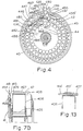
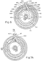
- the drum magazine shown in Figures 3A to 7B has a circularly cross-sectioned, pan-shaped housing 40 having a cover 41 within which is concentrically mounted an outer sprocket 42, an intermediate sprocket 43, and an inner sprocket 44.
- the drum, cover and each of the sprockets are made from moulded plastics and each of the sprockets is spool-shaped having a central tubular body and at each end of the body is a radially extending flange each having a like number of serrations around the outer periphery for holding cartridges.
- the serrations in the flanges adjacent a base 404 of the housing have a greater radial extent than the serrations in the arms adjacent the cover 41 to allow for the taper of a cartridge and so that the cartridge axes are approximately parallel to the axis of the housing.
- the inner sprocket 44 has serrations to hold each of cartridges C1-C24
- the intermediate sprocket 43 has a serration to hold each of cartridges C27-C57
- the outer sprocket 42 has a serration to hold each of cartridges C60C98.
- the sprockets are located in the housing 40 so that feed ramps 434, 441 on the housing, 455, 455' on the outer sprocket, and 471, 471' on the intermediate sprocket adopt the positions shown in Figure 3A and the feed ramp 434 extends to the base of cartridge C98, the feed ramp 455' extends to the base of cartridge C58 and the feed ramp 471' extends to the base of cartridge C25.
- the feed ramps are effective to scoop up the cartridges in the sprockets with which the ramps are associated and the ramps 441, 455', 471' act as guides for the cartridges.
- a nylon spindle' 45 secured to the housing and cover respectively by screws 400,401.
- the spindle has an ear 402 to which is secured one end of a sheet metal clock- type torsion spring 46, the other end of the spring 46 being secured to an aperture 403 in the inner sprocket 44.
- a pusher 47 is mounted on the inner sprocket 44.
- the pusher 47 has a spindle 405 positioned between the arms of the inner sprocket and pivotally mounted on the spindle 405 is a U-shaped arm 406 with the limbs of the U-shape within the confines of the inner sprocket flanges and adjacent a respective flange.
- the free ends of the U-shape are secured to the spindle 405 and a rod 407 having the approximate shape of a cartridge is welded to the base of the U-shape.
- the rod 407 has a tail 408 which is locatable in a serration of the inner sprocket and a bevelled top portion 409 (as viewed in Figure 7B) remote from the tail 408 to facilitate a bolt of the gun to which the magazine is secured to ride over the rod 407.
- a last round stop actuator 48 Connected to the spindle 405 between the U-shaped arm 406 and the wing of the inner sprocket adjacent the cover 41 is a last round stop actuator 48 comprising a spring arm 413 which is biassed toward the cover 41 and a button 414 which may contact a mechanism within a gun receiver to which the magazine is mounted so that when the last cartridge from the magazine is fired the bolt mechanism can be held in the cocked position.
- the bevelled portion 409 is provided so that the bolt will strike the pusher obliquely to the bevel.
- the tail 408 of the pusher is extended so that it may co-operate with a sprocket latch, as will be described later herein.
- the housing 40 has a feed throat 415 defined by a neck 416 having longitudinal sides in the axial direction of the housing and which is arranged to be located in the magazine well of a gun.
- the neck 416 has, on its right hand side (as viewed in Figures 3A and 4-7A), a pivotal lip 417 and on its left hand side an arcuate, fixed lip 418 extending over the feed throat.
- the neck of the magazine is shown located in a well of a gun (the well being shown in phantom lines).
- the pivoting lip 417 is mounted on an axle 419 and has an arm 420 with an arcuate upper surface 421, generally the same radius as a cartridge, and a tail 422 of such a length that, when the magazine is inserted into the well of a gun, the tail prevents rotation of the lip 417 so that it is not possible for the lip 417 to adopt the position shown in solid line in Figure 5B when mounted in the gun well.
- the lip 417 is biassed by a spring (not shown) so that the bottom of the lip (as viewed in Figure 5B) is normally horizontal, as shown in phantom lines.
- the distance between the lips 417 and 418 is arranged so that with the lip 417 spring biassed in a clockwise direction (as shown in Figure 4 for example and in Figure 5B in phantom lines) it is not possible for a cartridge to be removed from above the lips so the cartridges may not fall out of the magazine.
- the cartridge When the magazine is removed from the gun the cartridge may, however, be unloaded from the magazine in a direction perpendicular to the cartridge longitudinal axis by depressing lip 417.
- the cartridges are axially slid from the magazine by a bolt of the gun.
- a latching mechanism is provided to secure the magazine to the well of the gun and, conveniently, such a mechanism comprises a pair of pins which may be slidably mounted through one of the walls of the magazine well into co- operating holes in the neck 416 of the housing, these holes being referenced 423 in Figure 8A and one of the pins being shown in phantom lines in Figure 5B.
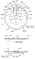
- the pan-shaped housing 40 shown in Figure 8A, 8B and 8C has an open top 424 to which the cover 41 is connected by internally screw threaded bosses 425 and located by pins 426 on each side of the neck 416.
- the housing 40 has a large internal diameter portion 427 for accommodating the body of the cartridge in the outer sprocket and a reduced internal diameter portion 428 in the region of the nose (bullet) portion of the cartridge and the portion 428 is connected to a base 429.
- the base has a circular protrusion 430, the interior of which acts as a bearing surface upon which the outer sprocket 42 and intermediate sprocket 43 rotate.
- the concentric protrusion 430 has a radially outer side 444 to concentrically locate the outer sprocket 42 and an inner side 445 to locate the intermediate sprocket 43 in a concentric fashion.
- the base 429 is dished to provide an inner boss 431 providing a bearing surface 432 and a concentric guide surface 433 for the inner sprocket 44.
- On the axis of the drum in the boss 431 is a hole for the screw 400.
- the fixed lip 418 is tapered inwardly of the housing so as to permit cartridges which are trapped by the lips 417,418 to be tilted such that the bullet is angled upwardly, the relieved portion of the fixed lip 418 permitting the cartridge body to rise slightly higher than the region of the cartridge toward the cannelore.
- This allows the cartridge to assume an ever increasing upward angle as it is driven in operation forwardly by the bolt so that it can enter the chamber smoothly without the base or cannelore end being forced downwardly.
- Such action is in distinction to the usual feed path of conventional magazines where, as the cartridge is driven forwardly, the bullet end is forced upwardly as it enters a feed ramp and the base end goes downwardly.
- a feed ramp 434 On the side of the feed throat 415 adjacent the fixed lip 418 is a feed ramp 434 having at its outer side a notch 435 to accommodate the serrations of the outer sprocket and at the inner side of the feed ramp 434 is a web guide 436 for the cartridges. Also provided on the same side of the throat as the fixed lip is a stop 437 for the outer sprocket.
- the pivoting lip 417 is located in a cutout defined by side walls 438 and 439 and a bottom part 440, the side wall 439 having an internal ramp portion 441 which also acts as a guide for feed ramp 434.
- a hole 442 in both side walls 438, 439 is forthe axle 419 of the pivoting lip 417.
- Both sides of the feed throat 415 have notches 433 which, in operation, abut against respective stop pins in the well of the gun to limit the extent of insertion of the magazine into the receiver.
- the internal diameter portion 428 has a recess 446 for co-operating with a latch 447 being in the form of a strip member provided on the outer sprocket.
- a recess instead of a recess, an aperture could be provided.
- the outer sprocket 42 has a tubular body 448 with flanges 449, 450 each having a like number of serrations 451 in which are located, between the flanges449, 450 cartridges.
- the serrations in flange 449 have a greater radial extent than those in flange 450.
- the body 448 has a reduced diameter portion 452 which sits within the internal diameter portion 428 of the housing and a concentric bearing surface 453 which engages the internal side of the protrusion 430.
- the body 448 has a feed aperture 454 to permit cartridges from the intermediate and inner sprockets to pass therethrough.
- the feed aperture 454 has feed ramps 455, 455' and a guide ramp 456 arranged to tilt the cartridge so that the bullet portion is inclined outwardly of the feed aperture 454.
- Located in the reduced diameter portion 452 is a stop 457 presenting a stop surface 458 for contacting the stop 437 of the housing and a further stop surface 459 for co-operating with a stop on the intermediate sprocket.
- the wall of the portion 452 has an aperture 460 shaped to house the latch 447 and to form a lip 461 against which a claw on a latch 462, connected to the intermediate spool, co-operates.
- Transversely to the aperture 460 is a hole 463 in a boss for a pin pivotally locating the latch 447.
- the reduced diameter portion 452 is arranged to locate the neck of a cartridge so as to maintain the cartridge with the required amount of tilt in the magazine.
- the latch 447 is bent into the shape of a dog leg so that it is able to overlap the latch 462.
- The. intermediate sprocket 43 shown in Figures 10A, 10B and 10C, is similar to the outer sprocket 42 and has a body 464 with a reduced diameter portion 465 and serrated flanges 466 and 467 between which cartridges are held.
- the radial extent of the serrations in flange 466 is greater than that of those in flange 467 for the reason discussed earlier.
- the end face of the reduced diameter portion 465 has a bearing surface 468 for rotating on the surface 430 of the housing and a recessed annular part 469, the inner periphery of which acts as a concentric guide surface to abut the inner side 445 of the housing.
- the intermediate sprocket has a feed aperture 470 having feed ramps 471, 471' and in which is disposed a cartridge 499 that is tilted by a guide ramp 472, as described in relation to the outer sprocket 42.
- the guide ramp 471' extends interiorally of the body 464.
- a stop 473 having a stop surface 474 for contacting the stop 459 on the outer sprocket 42 is provided on the reduced diameter portion 465 and in the side wall of the reduced diameter portion 465 is an aperture 475 for the latch 462 and a hole 476 is provided in a boss for a pin locating the latch 462.
- the inner sprocket 44 shown in Figures 11A and 11 B, has a body 477' with serrated side flanges 477, 478 and the body 477' has the rectangular aperture 403 within which one end of the spring 46 is located.
- the radial extent of the serrations in flange 477 is greater than that in the flange 478 to tilt the cartridge (shown in phantom lines).
- a notch 479 in the arm 477 within which the rod 407 of the pusher is locatable In the position between which the cartridges C1 and C25 (shown in phantom lines) are located is a notch 479 in the arm 477 within which the rod 407 of the pusher is locatable.
- a hole 480 is provided in each of the arms 477 and 478 forthe spindle 405 of the pusher.
- the latches 447 and 462 are both formed from strip material and, as best shown in Figure 4, both mounted on a respective pivot 481 and both biassed by a respective torsion spring 482, one end of which engages with an edge of slot 460, 475 respectively and the other end of which is bent into an L-shape and engages a tang 483, 484 respectively of the latches 447 and 462.
- the fingers 485 and 486 are both shaped to be inserted between cartridges C28 and C29 and between cartridges C2 and C3 respectively and to bear against cartridges C28 and C2 respectively.
- the tangs 483 and 484 have a radius portion which is arranged to be engaged by cartridge C26 and the rod 407 of the pusher 47 respectively.
- the cover 41 is a moulding made from clear plastics having a circular shape with six holes 490 located in protrusions of the cover for securing the cover to the housing 40.
- the cover has an axial hole 491 formed with notches 492 which act as a keyway for the spindle 45 and prevent the spindle 45 from rotating.
- the region surrounding the hole 491 is dished to provide a recess for the head of screw 401 and the underside of the cover has concentric ring slots 493, 494 for the flanges 450, 467 of the outer and intermediate sprockets respectively.
- the cover is locally thickened.
- a key 410 formed from ribs 411 with a root radius 412 between the ribs and the planar part of the cover.
- the cover has a neck 495 corresponding in part to the neck 416 of the housing and positioned partially down the neck and extending toward the hole 491 is a guide cover 496 which is chamfered toward the cover outer surface (as best shown in Figure 7B) to guide the actuator 48 in and out of the housing.
- the region 497 on each side of the ribs 411 is relieved to provide an improved depth of the ribs 411 upon which a keyway on the gun receiver may engage and because of slots 493 and 494, arcuate apertures 498 are formed.
- the guide cover 496 is recessed to provide a slot 496' of such depth that the cover 496 clears a normally provided last round stop in the gun receiver.
- the confluence of the relieved portion 497 and the thickened portion of the cover has a bevelled edge 497' to ease the location of the magazine onto the receiver keyway.
- the neck 495 is of such a length that it partially covers a top most cartridge to prevent the cartridge from moving rearwardly.
- Holes 490' are provided on the neck 495 within which the pins 426 on the housing are located and a protruding pin 491' extending on the underside of the cover forms part of the feed ramp for the cartridges.
- a water drain hole 492' is provided on the inside surface of the cover.
- the spring 46 drives the sprockets in an anti-clockwise direction (as viewed in the Figures 3A, 4, 5A and 6) so that starting with the magazine fully loaded, as shown in Figure 3A, cartridge C2 pushes on finger 486 which, because latch 462 is connected by pivot 481 to the intermediate sprocket 43, causes sprocket 43 to rotate in an anti-clockwise direction.
- the turning effort of intermediate sprocket 43 is, thus, applied to cartridge C28 which, in turn, applies a pressure through finger 485 of latch 447 to the outer sprocket 42 which, thus, also is rotated in an anti-clockwise direction.
- the last round stop actuator 48 Connected at one side of the arm 406 is the last round stop actuator 48 and as the pusher 47 extends up the feed ramp so the spring arm 413, which is biassed against the guide cover 496 on the cover 41, moves with the arm upwardly and.outwardly through the slot 496' in the cover. Until the pusher starts to move, the last round stop actuator 48 is mounted alongside the U-shaped arm 406 of the pusher. The action of the last round stop actuator button 414 is to move a bolt latch in the gun to latch the bolt assembly in an open position so that when the next magazine is inserted in the gun the bolt is already cocked.
- cartridges are inserted through the feed throat 415 in a direction perpendicular to the housing axis so that the cartridges are inserted into the upper surface 421 of the spring biassed pivoting lip 417 and downward pressure on the cartridges causes the pusher 407 to be partially depressed and the lip 417 to be rotated to the position shown in solid lines in Figure 5B.
- the pusher 47 is laid in its rest position on the inner sprocket and the insertion of further cartridges cause the cartridge C1 to be nested in the first of the serrations on the inner sprocket 44.
- cartridges C31 and C32 causes cartridges C28, C29 to depress the latch 462 so that the finger 486 is inserted between the cartridges C2, C3 (see Figure 4).
- the intermediate spool 43 and inner spool 44 causes the latch 462 to be fully depressed by cartridges C30, C29, C28 and the finger 486 to be firmly pushed between cartridges C2, C3, and to bear against cartridge C2.
- the function of the finger 486 is as follows: With the parts shown in the positions of Figure 5A the spring 46 exerts a pressure through cartridges C24, C25 and C26, causing cartridge C26 to be forced against the inner wall of the outer sprocket 42, thus resulting in undesirable friction. However, with the downward pressure of cartridge C30 on the latch 462, as shown in Figure 4, so finger 486 pulls cartridge C2 and, thus, the inner sprocket 44 in a clockwise direction relative to the intermediate sprocket 43. In this manner, the pressure from spring 46 upon cartridges C24, C25, and C26 is released and the cartridges C25, C26 have a small amount of freedom within the feed ramps 471' and 471 and the forementioned undesirable friction is removed.
- cartridges C64, C63, C62 force the finger 485 of latch 447 to pull the cartridge C28 in a clockwise direction and, hence, the intermediate sprocket 43 is moved in a clockwise direction relative to the outer sprocket 42 and the cartridges C57, C58 and C59 are freed from a tight fit against one another, in similar manner to the action of finger 486 upon cartridges C24, C25 and C26.
- the cartridges C58 and C59 have a small degree of freedom within the feed ramps 455' and 455 and undesirable friction between C59 and the inner wall of the housing 40 is eliminated.
- all of the cartridges in the magazine are loosely held in the serrations or feed ramps and frictional forces are reduced to a minimum.
- the magazine is completely filled by inserting cartridges up to C100 and the magazine is then in the position shown in Figure 3A.
- the provision of the latches 447 and 462 is not necessary to the working of the invention, although they are considered to be extremely desirable for the dual function they each perform.
- the ears 487, 488, in conjunction with lips 489, 461 respectively prevent rotation of sprockets 42, 43 respectively to permit the magazine to be loaded through the feed throat 415.
- the fingers 485,486 of the latches permit drive from the intermediate sprocket to the outer sprocket to be through the latch 447 and from the inner sprocket to the intermediate sprocket through the latch 462 respectively, thereby enabling all of the cartridges in the magazine except cartridges C100, C99 to have a small amount of freedom of movement within the magazine.
- latches having similar functions although possibly requiring differing components to perform each of the two functions could be designed, with advantage, for use with the Soumi-type magazine.
- FIG. 13 there is shown an alternative form of last round stop actuator in which a compression spring 413' and plunger 414' are inserted in a bore of the rod 407.
- the action of the plunger 414' is such that as the rod 407 moves up the feed ramp so the plunger 414' is extended by the force of spring 413' and when the arm 406 is fully extended so the plunger 414' abuts the last round stop mechanism in the gun receiver.
Landscapes
- Engineering & Computer Science (AREA)
- General Engineering & Computer Science (AREA)
- Portable Nailing Machines And Staplers (AREA)
Claims (27)
Priority Applications (5)
| Application Number | Priority Date | Filing Date | Title |
|---|---|---|---|
| DE8484101403T DE3072102D1 (en) | 1980-12-11 | 1980-12-11 | Drum magazine for a gun |
| DE8080304480T DE3070718D1 (en) | 1980-12-11 | 1980-12-11 | Drum magazine for a gun |
| AT80304480T ATE13591T1 (de) | 1980-12-11 | 1980-12-11 | Trommelmagazin fuer eine feuerwaffe. |
| EP19840101403 EP0123798B1 (de) | 1980-12-11 | 1980-12-11 | Trommelmagazin für eine Feuerwaffe |
| EP19800304480 EP0054089B1 (de) | 1980-12-11 | 1980-12-11 | Trommelmagazin für eine Feuerwaffe |
Applications Claiming Priority (2)
| Application Number | Priority Date | Filing Date | Title |
|---|---|---|---|
| GB8039745 | 1980-12-11 | ||
| EP19800304480 EP0054089B1 (de) | 1980-12-11 | 1980-12-11 | Trommelmagazin für eine Feuerwaffe |
Related Child Applications (1)
| Application Number | Title | Priority Date | Filing Date |
|---|---|---|---|
| EP84101403.8 Division-Into | 1980-12-11 |
Publications (2)
| Publication Number | Publication Date |
|---|---|
| EP0054089A1 EP0054089A1 (de) | 1982-06-23 |
| EP0054089B1 true EP0054089B1 (de) | 1985-05-29 |
Family
ID=26080007
Family Applications (1)
| Application Number | Title | Priority Date | Filing Date |
|---|---|---|---|
| EP19800304480 Expired EP0054089B1 (de) | 1980-12-11 | 1980-12-11 | Trommelmagazin für eine Feuerwaffe |
Country Status (1)
| Country | Link |
|---|---|
| EP (1) | EP0054089B1 (de) |
Families Citing this family (2)
| Publication number | Priority date | Publication date | Assignee | Title |
|---|---|---|---|---|
| US6408837B1 (en) * | 1999-09-13 | 2002-06-25 | Johnson Research & Development Co. | Toy gun with magazine |
| CN113338592B (zh) * | 2020-03-03 | 2022-04-01 | 广东博智林机器人有限公司 | 一种弹鼓装置和找平机器人 |
Family Cites Families (14)
| Publication number | Priority date | Publication date | Assignee | Title |
|---|---|---|---|---|
| DE649860C (de) * | 1937-09-04 | Mauser Werke Ag | Mittelschaftsmagazin, insbesondere fuer Selbstladewaffen | |
| DE44923C (de) * | F. MANNLICHER in Wien | Neuerung an Cylinderverschlufs-Gewehren mit Trommel-Magazin | ||
| GB191309478A (en) * | 1913-04-22 | 1913-09-18 | Oliver Imray | Improvements in or relating to Automatic Pistols. |
| FR491235A (fr) * | 1918-08-10 | 1919-05-27 | Aubert Freres Soc | Chargeur pour revolvers automatiques |
| FR571475A (fr) * | 1923-10-04 | 1924-05-17 | Dansk Rekylriffel Syndikat As | Magasin à cartouches en forme de tambour pour mitrailleuses ou autres armes semblables |
| BE417737A (de) * | 1935-10-02 | |||
| GB472784A (en) * | 1936-11-17 | 1937-09-30 | Oskar Alfred Ostman | Machine gun magazines |
| BE437553A (de) * | 1939-01-31 | |||
| BE441561A (de) * | 1939-10-14 | |||
| US2321720A (en) * | 1941-05-13 | 1943-06-15 | Automatic Appliance Corp | Magazine for firearms |
| CH237418A (de) * | 1943-10-01 | 1945-04-30 | Oerlikon Buehrle Ag | Munitionsmagazin für automatische Feuerwaffen. |
| US2715290A (en) * | 1949-04-21 | 1955-08-16 | Earle M Harvey | Magazine for automatic firearms |
| US2585738A (en) * | 1949-12-13 | 1952-02-12 | Savage Arms Corp | Cartridge guide device for repeating firearms |
| US3239959A (en) * | 1964-03-24 | 1966-03-15 | Sturm Ruger & Co | Removable magazine for repeating gun |
-
1980
- 1980-12-11 EP EP19800304480 patent/EP0054089B1/de not_active Expired
Also Published As
| Publication number | Publication date |
|---|---|
| EP0054089A1 (de) | 1982-06-23 |
Similar Documents
| Publication | Publication Date | Title |
|---|---|---|
| US4384508A (en) | Drum magazine for a gun | |
| US4445418A (en) | Drum magazine for a gun | |
| US4893546A (en) | Automatic pistol | |
| US4413546A (en) | Drum magazine for carbines or the like | |
| AU649738B2 (en) | Firearm | |
| US5099595A (en) | Magazine for a firearm | |
| US4970820A (en) | Device for rapidly loading rimmed cartridges into large capacity firearm magazines | |
| US5056252A (en) | Firearm magazine | |
| US4742634A (en) | Automatic slide guard | |
| US4413437A (en) | Cartridge magazine | |
| EP0039553B1 (de) | Trommelverriegelung für Revolver | |
| EP0123798B1 (de) | Trommelmagazin für eine Feuerwaffe | |
| EP0044632A1 (de) | Bedienungsmechanismus für Handfeuerwaffen | |
| EP0054089A1 (de) | Trommelmagazin für eine Feuerwaffe | |
| KR870001687B1 (ko) | 기관총의 드럼식 탄창 | |
| CA1181620A (en) | Drum magazine for a gun | |
| KR870001686B1 (ko) | 기관총의 드럼식 탄창 | |
| US4757628A (en) | Shark saber | |
| KR870001688B1 (ko) | 기관총의 드럼식 탄창 | |
| JPH0796999B2 (ja) | ピストル | |
| US3853035A (en) | Gas fired machine gun | |
| CA1164256A (en) | Actuating mechanisms for small arms | |
| EP0434160A1 (de) | Verfahren zum zeitlichen Öffnen eines Munitionsmagazins und Vorrichtung zu seiner Ausführung | |
| FI63488B (fi) | Laddningsslid foer automateldvapen med framaot roerlig pipa | |
| CA1125074A (en) | Double action revolver apparatus and method |
Legal Events
| Date | Code | Title | Description |
|---|---|---|---|
| PUAI | Public reference made under article 153(3) epc to a published international application that has entered the european phase |
Free format text: ORIGINAL CODE: 0009012 |
|
| AK | Designated contracting states |
Designated state(s): AT BE CH DE FR IT LI LU NL SE |
|
| 17P | Request for examination filed |
Effective date: 19821116 |
|
| ITF | It: translation for a ep patent filed | ||
| GRAA | (expected) grant |
Free format text: ORIGINAL CODE: 0009210 |
|
| AK | Designated contracting states |
Designated state(s): AT BE CH DE FR IT LI LU NL SE Kind code of ref document: B1 Designated state(s): AT BE CH DE FR IT LI LU NL SE |
|
| REF | Corresponds to: |
Ref document number: 13591 Country of ref document: AT Date of ref document: 19850615 Kind code of ref document: T |
|
| REF | Corresponds to: |
Ref document number: 3070718 Country of ref document: DE Date of ref document: 19850704 |
|
| ET | Fr: translation filed | ||
| PG25 | Lapsed in a contracting state [announced via postgrant information from national office to epo] |
Ref country code: LU Free format text: LAPSE BECAUSE OF NON-PAYMENT OF DUE FEES Effective date: 19851231 |
|
| PLBE | No opposition filed within time limit |
Free format text: ORIGINAL CODE: 0009261 |
|
| STAA | Information on the status of an ep patent application or granted ep patent |
Free format text: STATUS: NO OPPOSITION FILED WITHIN TIME LIMIT |
|
| 26N | No opposition filed | ||
| PGFP | Annual fee paid to national office [announced via postgrant information from national office to epo] |
Ref country code: NL Payment date: 19871231 Year of fee payment: 8 |
|
| PGFP | Annual fee paid to national office [announced via postgrant information from national office to epo] |
Ref country code: SE Payment date: 19891231 Year of fee payment: 10 |
|
| PG25 | Lapsed in a contracting state [announced via postgrant information from national office to epo] |
Ref country code: NL Effective date: 19900701 |
|
| NLV4 | Nl: lapsed or anulled due to non-payment of the annual fee | ||
| PGFP | Annual fee paid to national office [announced via postgrant information from national office to epo] |
Ref country code: DE Payment date: 19901123 Year of fee payment: 11 |
|
| PG25 | Lapsed in a contracting state [announced via postgrant information from national office to epo] |
Ref country code: SE Effective date: 19901212 |
|
| PGFP | Annual fee paid to national office [announced via postgrant information from national office to epo] |
Ref country code: FR Payment date: 19901219 Year of fee payment: 11 |
|
| PGFP | Annual fee paid to national office [announced via postgrant information from national office to epo] |
Ref country code: AT Payment date: 19901228 Year of fee payment: 11 |
|
| ITTA | It: last paid annual fee | ||
| PGFP | Annual fee paid to national office [announced via postgrant information from national office to epo] |
Ref country code: BE Payment date: 19910114 Year of fee payment: 11 |
|
| PGFP | Annual fee paid to national office [announced via postgrant information from national office to epo] |
Ref country code: CH Payment date: 19910129 Year of fee payment: 11 |
|
| PG25 | Lapsed in a contracting state [announced via postgrant information from national office to epo] |
Ref country code: AT Effective date: 19911211 |
|
| PG25 | Lapsed in a contracting state [announced via postgrant information from national office to epo] |
Ref country code: LI Effective date: 19911231 Ref country code: CH Effective date: 19911231 Ref country code: BE Effective date: 19911231 |
|
| BERE | Be: lapsed |
Owner name: CHARTERED INDUSTRIES OF SINGAPORE PRIVATE LTD Effective date: 19911231 |
|
| PG25 | Lapsed in a contracting state [announced via postgrant information from national office to epo] |
Ref country code: FR Effective date: 19920831 |
|
| REG | Reference to a national code |
Ref country code: CH Ref legal event code: PL |
|
| PG25 | Lapsed in a contracting state [announced via postgrant information from national office to epo] |
Ref country code: DE Effective date: 19920901 |
|
| REG | Reference to a national code |
Ref country code: FR Ref legal event code: ST |
|
| EUG | Se: european patent has lapsed |
Ref document number: 80304480.9 Effective date: 19900829 |