EP0054090A1 - Abstellen von von Hand bewegten Fahrzeugen - Google Patents
Abstellen von von Hand bewegten Fahrzeugen Download PDFInfo
- Publication number
- EP0054090A1 EP0054090A1 EP80304501A EP80304501A EP0054090A1 EP 0054090 A1 EP0054090 A1 EP 0054090A1 EP 80304501 A EP80304501 A EP 80304501A EP 80304501 A EP80304501 A EP 80304501A EP 0054090 A1 EP0054090 A1 EP 0054090A1
- Authority
- EP
- European Patent Office
- Prior art keywords
- trolley
- trolleys
- stack
- outlet
- conveyor
- Prior art date
- Legal status (The legal status is an assumption and is not a legal conclusion. Google has not performed a legal analysis and makes no representation as to the accuracy of the status listed.)
- Withdrawn
Links
- 230000007246 mechanism Effects 0.000 claims abstract description 10
- 235000006696 Catha edulis Nutrition 0.000 claims 1
- 240000007681 Catha edulis Species 0.000 claims 1
- 238000003780 insertion Methods 0.000 description 4
- 230000037431 insertion Effects 0.000 description 4
- 238000009434 installation Methods 0.000 description 3
- 238000012986 modification Methods 0.000 description 3
- 230000004048 modification Effects 0.000 description 3
- 229910000831 Steel Inorganic materials 0.000 description 2
- 239000010959 steel Substances 0.000 description 2
- 238000005352 clarification Methods 0.000 description 1
- 238000010276 construction Methods 0.000 description 1
- 238000013461 design Methods 0.000 description 1
- 238000010586 diagram Methods 0.000 description 1
- 230000000694 effects Effects 0.000 description 1
- 238000000034 method Methods 0.000 description 1
- 238000013021 overheating Methods 0.000 description 1
- 230000000717 retained effect Effects 0.000 description 1
- 238000004804 winding Methods 0.000 description 1
- 239000002023 wood Substances 0.000 description 1
Images


Classifications
-
- G—PHYSICS
- G07—CHECKING-DEVICES
- G07F—COIN-FREED OR LIKE APPARATUS
- G07F7/00—Mechanisms actuated by objects other than coins to free or to actuate vending, hiring, coin or paper currency dispensing or refunding apparatus
- G07F7/06—Mechanisms actuated by objects other than coins to free or to actuate vending, hiring, coin or paper currency dispensing or refunding apparatus by returnable containers, i.e. reverse vending systems in which a user is rewarded for returning a container that serves as a token of value, e.g. bottles
- G07F7/0618—Mechanisms actuated by objects other than coins to free or to actuate vending, hiring, coin or paper currency dispensing or refunding apparatus by returnable containers, i.e. reverse vending systems in which a user is rewarded for returning a container that serves as a token of value, e.g. bottles by carts
- G07F7/0636—Mechanisms actuated by objects other than coins to free or to actuate vending, hiring, coin or paper currency dispensing or refunding apparatus by returnable containers, i.e. reverse vending systems in which a user is rewarded for returning a container that serves as a token of value, e.g. bottles by carts in which the trolleys or carts are kept in a restricted zone such as a coral-like enclosure, or are passing a gate before use is possible
- G07F7/0645—Mechanisms actuated by objects other than coins to free or to actuate vending, hiring, coin or paper currency dispensing or refunding apparatus by returnable containers, i.e. reverse vending systems in which a user is rewarded for returning a container that serves as a token of value, e.g. bottles by carts in which the trolleys or carts are kept in a restricted zone such as a coral-like enclosure, or are passing a gate before use is possible in which the trolleys or carts are kept in a box or container designed to transport or store a row of trolleys or carts as a whole
-
- G—PHYSICS
- G07—CHECKING-DEVICES
- G07F—COIN-FREED OR LIKE APPARATUS
- G07F7/00—Mechanisms actuated by objects other than coins to free or to actuate vending, hiring, coin or paper currency dispensing or refunding apparatus
- G07F7/06—Mechanisms actuated by objects other than coins to free or to actuate vending, hiring, coin or paper currency dispensing or refunding apparatus by returnable containers, i.e. reverse vending systems in which a user is rewarded for returning a container that serves as a token of value, e.g. bottles
- G07F7/0618—Mechanisms actuated by objects other than coins to free or to actuate vending, hiring, coin or paper currency dispensing or refunding apparatus by returnable containers, i.e. reverse vending systems in which a user is rewarded for returning a container that serves as a token of value, e.g. bottles by carts
- G07F7/0636—Mechanisms actuated by objects other than coins to free or to actuate vending, hiring, coin or paper currency dispensing or refunding apparatus by returnable containers, i.e. reverse vending systems in which a user is rewarded for returning a container that serves as a token of value, e.g. bottles by carts in which the trolleys or carts are kept in a restricted zone such as a coral-like enclosure, or are passing a gate before use is possible
Definitions
- the present invention relates to the storage of independently movable and stackable objects comprising trolleys and like hand-propelled vehicles and has particular but not exclusive application to the storage of supermarket trolleys and luggage trolleys at railway stations and airports and the like.
- Such trolleys are free-standing handcarts usually havina four wheels and supporting a frame which includes a receptacle for goods (either purchased or luggage in the case of a railway or airport trolley) and the trolley serves as a convenient means for carrying the selected goods or luggage around the supermarket or on railway platforms and around airports.
- trolleys are intended primarily for use within the confines of the shop or station or airport etc. it has become increasingly common for them to be used to convey goods to a place, usually a car park, remote from the well defined confines of the shop or other establishment. Not all such trolleys are returned to the originating establishment and the collection of abandoned trolleys is not only an onerous task but is also expensive. Furthermore abandoned trolleys are a frequent object of vandalism and it is an object of the present invention to provide a safe and convenient storage system for such trolleys and other hand-propelled vehicles which can readily be adapted to encouraqe their return to the establishment from which they have been borrowed.
- a storage facility for storing independently movable and stackable objects (hereinafter referred to as trolleys) comprises
- the conveyor means is adapted to engage the underside of an introduced trolley to transmit drive thereto.
- the driving engagement between the conveyer means and the trolleys is frictional and allows for slip between the conveyor means and the trolleys.
- the conveyor means will slip relative to the trolley after the latter has become stationary at the end of the stack of trolleys (or at the outlet end of the facility in the event that no trolleys exist therein).
- the conveyor means may comprise a conveyor belt and the underside of each trolley includes a transversely extendin q member which will be engaged by the upper surface of the conveyor belt and will be sufficiently gripped thereby to transmit drive to the trolley as hereinbefore mentioned.
- the same conveyor belt will preferably, of course, also serve to advance a stack of trolleys towards the outlet when a leading trolley in the stack is released through the outlet, and the advance of said stack may initiate such trolley release at output under the control of said releasing means.
- the conveyor belt may be adapted to lift the front of a trolley, thereby to drive it on its rear wheels, guides beinq provided for guiding said rear wheels (which may normally be turnable)so that the trolley is driven towards the outlet.
- the facility includes means for sensing when the last available trolley has been removed from the stack and preferably means is provided for indicating that the facility is empty of available trolleys when that condition is sensed.
- further sensing means is provided for generating a warning signal when the facility is full of trolleys and means is provided for indicating that the facility is full and that no further trolleys should be introduced therein.
- locking means is provided for locking the inlet to the facility in the event that a full condition is sensed.
- a coin-freed mechanism is provided at the outlet of a trolley storage facility so that an outlet is opened and a trolley is obtained therethrough only on the insertion of a coin.
- coin it is intended to mean a coin of the realm or a token which may for example be purchased against a deposit.
- an inlet end of the storage facility can be provided with a coin outlet through which a single coin is allowed to pass after a trolley has been satisfactorily entered into the facility and has been stacked therein.
- Aqain the expression "coin” is intended to cover both coins of the realm and tokens depending on the system operating.
- the facility may comprise a framework having display shelving along at least part of at least one side thereof.
- the facility may comprise the - shelving to be mounted adjacent a wall or may comprise a display shelving island for a supermarket or like establishment.
- the framework may support similar display shelving for the display and sale of periodicals, newspapers and books or other goods or may provide a support for display shelving for a cafeteria or the like.
- the important aspect of this feature of the invention is that the space required by the facility need not be lost or wasted and need not be extra to space already used by the establishment whether it be a shop or travel terminal.
- a display stand for a shop or public place comprises an elongate hollow framework having display storage means along at least one elongate face thereof and further comprising at one end an inlet and at the other end an outlet each adapted to pass one at a time a trolley into or out of the hollow interior of the framework, conveyor means for conveying objects introduced through the inlet in a direction towards the outlet to produce a stack of the introduced object with any previously introduced objects already stacked therein and means for releasing one object at a time through the outlet.
- the conveyor means is operated each time a trolley is to be introduced into the stack or is to leave the stack.
- the same conveyor means serving to move the introduced trolley to the stack may also serve to remove a wanted trolley from the remote end of the stack, although preferably a supplementary conveyor is used to assist fulfilment of the latter purpose.
- the entire stack of trolleys is moved in a direction towards the outlet whenever the leading trolley is called up from the stack and is passed through the outlet. In this way the stack is continually advanced in a direction towards the outlet as trolleys are called up so that there is always a trolley at the leading end of the stack ready to be released through the outlet (assuming that there are trolleys within the facility).
- each operation of the conveyor means is arranged to be of sufficient duration to move a single trolley from the inlet position to the position which the lead trolley in the stack would occupy so that if there are no trolleys in the facility when a trolley is introduced thereinto, the conveyor means will move that trolley all the way to the position at which it will be picked up and released through the outlet upon demand. In this way it is ensured that even if there is only one trolley in the facility, it will be available for call-up through the outlet upon the appropriate call-up procedure beinq initiated.
- Fiqures 1 to 3 of the drawings are intended for internal use within stores, supermarkets and the like.
- An alternative arrangement with slight modifications is equally applicable to outdoor use at railway stations and car parks and the like and a still further alternative basically similar to the arrangement shown in Figures 1 to 3 may be used at airport terminals and the like.
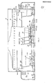
- the facility comprises an elongate framework 10 having mounted on one or both sides thereof shelf racking 12, 14, 16.
- the framework may be against a wall or constitute a free-standing island.
- the structure is conveniently fabricated from sheet steel or wood and steel and the interior is essentially hollow and serves to house an elongate conveyor (to be described) and the stack of trolleys which are introduced one at a time at one end past a hand rail and can be removed one at a time from the other end upon insertion of a coin or token the value of which can be recovered only by the subsequent insertion of a trolley into the facility.
- the framework 10 and shelving 12, 14, 16 etc. would be replaced by a generally tubular construction (not shown) covered for example with galvanised wire mesh and all the electrical equipment would be flame-proofed and waterproofed or replaced by hydraulic or pneumatic equivalents.
- the facility is adapted to receive supermarket trolleys of which one is shown at 18 and others are shown in outline at 20, 22 and 24. It is a feature of such trolleys that they can be stacked in the manner shown by the relative positions of 20, 22 and 24 with the nose of each trolley entering the rear of the trolley in front and passing between the handle and the rear wheels thereof. To this end the rear of each such trolley comprises a hinged flap which lifts up as the nose of a following trolley is introduced into the rear thereof.
- Such trolleys are well known. Typically, an elongate facility about 11 metres long will accommodate up to 50 trolleys.
- the trolley 20 is shown at the head of the stack-and is available to be released from the stack through exit doors one of which is shown at 26.
- the doors are sliding doors and a second door similar to that shown at 26 is provided on the other side of the exit or outlet and a trolley 23 is shown just passing through the outlet in the direction of the arrow 30.
- an inlet with two sliding doors similar to the sliding doors at the outlet end one of which is designated by reference numeral 31 in Figure 1.
- the two doors can be seen in Figure 2 and the second door (not visible in Figure 1) is denoted by reference numeral 32.
- An input ramp 36 is adapted to receive and raise the front end of a trolley as it is pushed towards the opening 34 and an infra-red sensor 38 is located in the ramp 36 so that as a trolley such as 18 is pushed thereover the front transversely extending axle (or a similar member extending between the two front wheels one of which is shown at 40) passes over the switch and activates the same. Circuits (hereinafter to be described) respond thereto and produce operation of motor drive means 42 for opening the doors 31 and 32 as the trolley is pushed theretowards up the ramp 36.
- the ramp 36 causes the transverse rail or axle (previously mentioned) to be lifted onto the lead-in section 44 of a conveyor of which the belt is denoted by reference numeral 46.
- the belt is moved in the direction of the arrow 48 and is driven by a drive motor 50.
- a subsidiary conveyor belt 52 serves to pick up the front end of the trolley 20 (when the latter is released) to drive the trolley in a generally forward direction and downward towards the outlet.
- the trolley By having a downward ramp as at 54 leading towards the outlet, so the trolley will gain momentum as it runs down the ramp and sufficient momentum is imparted thereto for it to pass completely through the opening at the far end of the facility (previously described) provided the two doors, of which one is shown at 26, are open.
- a trolley in that condition is shown at 28, as previously described.
- the conveyor belt 46 is mounted centrally of a box section conveyor housing of which the input and output ramps 36 and 54 may be integral or separate members secured thereto.
- the main box section is denoted by reference numeral 56 and this can be seen not only in Figure 1 but also in Figure 2.
- the front end of the trolley is supported in lifted condition by the belt 46 as hereinbefore mentioned.
- the rear end of the trolley is supported on its two rear wheels (of which one is shown at 58) and these run on two platforms 60 and 62 (see Figure 3 and compare with Figure 1) forming part of the box section conveyor housing and which have thereon guide rails 64 and 66 for retaining the rear wheels laterally.
- the conveyor belt 46 When the conveyor belt 46 is operative to drive forward the trolley 18, it can also be operative, if a trolley output is called for at the front of a stack, to advance any remaining stack of trolleys as far as permitted towards the outlet.
- a trolley stop (not shown in detail) denoted by reference numeral 68.
- the belt drive motor 50 is started and the stack of trolleys moves in a generally forward direction (i.e. to the right as shown in Figure 1) until the front transverse axle or member of the trolley 20 drops down onto the supplementary conveyor belt 52 from where it is drawn in a downward direction towards the outlet.
- the action of the trolley stop is to release only one trolley and it immediately re-positions so as to prevent the next trolley passing the trolley stop.
- the released trolley runs down towards the outlet and at the same time the drive motor 70 for the outlet doors of which one is shown at 26, is operated causing the doors to open and allow the trolley to pass therethrough.
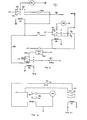
- Figure 3a illustrates one form of stop device.
- This comprises a pair of pivoted arms 72 mounted one on either side of the belt 4 6 on pivots 74 so that the head of each. of the arms (designated by reference numeral 76) extends above the level of the belt 46 for engagement by the leading edge of the transverse member 78 extending across between the front wheels of the leading trolley 20 (see Figure 1).
- the direction of movement of the trolleys in Figure 1 i.e. in the direction of the arrow 48
- Figure 3a designated by reference numeral B0
- each of the arms is joined by a transversely extending strut (not shown) and at each end of the strut is located a roller or wheel 82.
- Each of the arms 72 is biassed by means of a spring 84 attached to a fixed part of the overall assembly 86.
- a solenoid 88 having a moving armature 90 which normally (when the solenoid is de-energised) hangs down and acts as a stop against which the transversely extending strut (not shown) between the lower ends of the two arms 72 abuts.
- a second stop 92 is provided for each arm (or at least one of the arms) towards the upper end and to the rear of each of the arms 72.
- the solenoid 88 is energised, thereby lifting the movable armature 90. This frees the arms 72 and will allow them to pivot in an anti-clockwise direction about the pivot 74 (as shown in Figure 3a) under the weight of the leading trolley (20) and this will allow the leading trolley to move (with the belt 46) onto the downwardly extending ramp section 54 (see Figure 1),' whence the drive to the outlet is taken over by the supplementary conveyor 52.
- the springs 84 cause the two arms 72 to revert to their original generally upright position as shown in Figure 3a and after a specified time interval the solenoid is de-energised causing the armature 90 to drop again so as to provide a stop for the transversely extending strut (not shown).
- the second trolley in line (22 in Fiqure 1) is prevented from passing the stop position as denoted by the heads 76 of the two arms 72 and the second trolley must wait until it is released in a similar manner to that just described.
- a relay K1 includes a holding contact set 94 and the holding circuit is completed through a normally closed switch SW1. This latter is located in the path of the trolley and is actuated as the trolley moves down the ramp section 54. With switch 1 opened momentarily relay K1 drops out.
- the relay is energised initially by a signal from a coin-need mechanism shown at 96 in Figure 1.
- the mechanism is adapted to receive a coin or token and produce an electrical pulse along the line 98 (see Figure 4) for each such coin or token inserted therein.
- the relay K1 includes a second contact set 100 which provides power (when the relay is energised) to the trolley release solenoid 88 (see Figure 3a and Figure 1) and a third contact set 102 provides power to a second relay K2 which includes a holding contact set 104, the holding circuit being maintained through a normally closed switch SW2.
- This latter switch is associated with the doors at the outlet (of which one is shown at 26 in Figure 1).
- the signal from the coin-freed mechanism 96 is also used to initiate a door-opening sequence and power is supplied to the motor 70 as required to initially open the doors of which one is shown at 26 and then to close same.
- the switch SW2 is normally closed but when the doors at the outlet (26 etc.) are finally fully closed switch SW2 opens and breaks the holding circuit for relay K2.
- Relay K2 therefore supplies power to the belt drive motor 50 via contact set 106 and removes this drive after the doors at the outlet have opened and shut indicating that a trolley has successfully been removed from the stack.
- Figure 9a shows the circuit associated with the input end of the facility.
- the sequence is initiated by the infra-red input sensor 38 which provides a pulse of current to relay DK2.
- Operation of the relay produces a current pulse along line 108 and since at that stage the doors are not open (i.e. doors 31 and 32) switch 8 is in its normally closed condition and relay DK1 is energised.
- the relay DK1 includes a holding circuit through contact set 110. The relay is held in until the doors 31 and 32 are fully open when switch 8 is opened momentarily breaking the holding circuit for the relay.
- Relay DK2 is not held in by any holding circuit and consequently a third relay DK3 is provided which does include a holding circuit through a normally closed contact set 114 on the relay DK2 and a normally closed switch SW9 which is opened when tne doors 31 and 32 are closed.
- Relay DK3 is thus energised at the beginning of the cycle and de-energises when the doors are finally closed. This provides an output along line 116 to a normally open contact set at 118 on relay DK4.
- Relay DK4 is energised when the mag. switch 122 is closed (see Figure 9a) and provides power for relay DK3.
- FIG. 9b shows the interlock circuits associated with the output doors (26).
- Switch SW20A is normally open and is only closed if a trolley is at the position of trolley 22 in the stack. Thus, if no trolley is available, relay DK/01 cannot operate, and the motor for opening the doors 26 etc. is unable to operate.
- SW10 (associated with output doors 26 etc.) is normally open, and is closed by the passage of a trolley through the doors 26 etc. to provide power to the motor 70 for closing the doors.
- Power to the motor 70 is supplied through normally closed switch SW21A which is opened to stop the motor when the doors finally close.
- switch 3 which provides a pulse to relay K4 (see Figure 5).
- This relay has a holding circuit normally in contact set 126 and normally closed switch SW4.
- a second normally open contact set 128 provides power along line 130 to a second relay K3 which includes its own holdina circuit via normally closed timer switch T1.
- the contact set operating as the hold-on contact set is designated by reference numeral 132.
- Another normally open contact set 134 provides a further output to the main belt drive motor 50 along line 136 whilst the remaining contact set 138 provides an output to the timer motor M1 (see Figure 5).
- M1 is not shown in Figure 1).
- M1 is a motor which together with a cam causes a switch T1 to be opened at the end of a specified period of time. This interrupts the hold-on circuit for relay K3 and causes K3 to drop out at the end of the timing period.
- a second N/ O switch T2 associated with timer motor M1 supplies current to a relay K5 (see Figure 5) which includes a holding circuit through contacts 137 and a N/0 switch T3 associated with a second timer motor and cam M2. The latter is powered when K5 is operated, via contacts 139. N/O contacts 141 supply power to the main belt motor.
- relay K4 Whilst relay K4 is energised power is available along line 140 to the mag. P/U switch 120 so that a solenoid associated with a pay-out device (not shown in Figure 1) is energised and a coin or token at the end of the coin-return conveyor (shown at 142 in Figure 1) can be made available in the coin/token return chute 144.
- FIG 6 shows how the drive for a coin-transport conveyor 142 is obtained via relays K7 and K8.
- Relay K7 is operated from the signal from the coin switch (i.e. line 98 in Figure 4) and provides power along line 144 through normally closed timer switch T2 to the winding of a second relay K8. Operation of this relay provides power to a timer motor M2 and rotation of the motor and a cam (not shown) associated therewith eventually opens switch T2 thereby breaking the hold circuit which has previously been established for relay K8.
- Relay K7 only operates momentarily.
- the relay K3 provides power to the coin-conveyor motor along line 146.
- Figure 7 shows that the line 136 does not gc directly to the belt motor 50 but supplies power to a wincing of a contactor K9. Normally open contacts 143 provide the actual power to the belt motor 50 when the contactor is operated.
- a belt broken switch indicates a main conveyor belt break and causes a switch SW14 to open.
- Relay K10 is normally held energised through the normally closed switch SW14 and in the event that the switch SW14 opens, K10 drops out so removing the mains voltage from the line 150. This means that no further power is available for the belt motor via normally open contact set 143 of the contactor K9. Although this means that the machine will immediately stop in the event of a belt failure, it will also be seen that this prevents undue damage to the belt or other equipment due to the motor continuing to run, either overheating or causing the belt to become wrapped around the various moving parts of the conveyor belt line.
- a switch SW6 is provided to indicate if the stack is empty.
- Switch SW6 is connected in series with the power to the door motor 70 (see Figure 1) and also when operated causes a sign to become illuminated tc the effect that the line is empty.
- SW6 is to inhibit the operation of the doors 26 etc. and can also be arranged to introduce a diversion into the coin path in the coin-freed mechanism 96 so that any coin inserted is returned to the user.
- switches SW4 and SW5 are provided. These switches are located along the length of the conveyor such that when a stacked trolley occupies the position at 13 both switches are closed.
- the condition causes relay K11 to operate and this provides power to a "stack full" sign along line 152 via contact set 148.
- the normally closed contact set 154 provides power to the positive side of switch SW2.
- the normally closed contact set 160 associated with relay K12 provides power along line 162 to the device in the coin-freed mechanism 96 to prevent the insertion of coins and/or deflect inserted coins to a coin-return chute.
- the conveyor means may extend along a non- straight path such as a U-path between the inlet and the outlet , for example to facilitate increased capacity.
- the input ramp may lead downwards; the supplementary ramp at output may lead upwards.
- the coin mechanisms although not an essential part of the control, clearly encourage the return of trolleys to the facility and are materially advantageous for this purpose.
Landscapes
- Physics & Mathematics (AREA)
- General Physics & Mathematics (AREA)
- Discharge Of Articles From Conveyors (AREA)
Priority Applications (1)
| Application Number | Priority Date | Filing Date | Title |
|---|---|---|---|
| EP80304501A EP0054090A1 (de) | 1980-12-12 | 1980-12-12 | Abstellen von von Hand bewegten Fahrzeugen |
Applications Claiming Priority (1)
| Application Number | Priority Date | Filing Date | Title |
|---|---|---|---|
| EP80304501A EP0054090A1 (de) | 1980-12-12 | 1980-12-12 | Abstellen von von Hand bewegten Fahrzeugen |
Publications (1)
| Publication Number | Publication Date |
|---|---|
| EP0054090A1 true EP0054090A1 (de) | 1982-06-23 |
Family
ID=8187332
Family Applications (1)
| Application Number | Title | Priority Date | Filing Date |
|---|---|---|---|
| EP80304501A Withdrawn EP0054090A1 (de) | 1980-12-12 | 1980-12-12 | Abstellen von von Hand bewegten Fahrzeugen |
Country Status (1)
| Country | Link |
|---|---|
| EP (1) | EP0054090A1 (de) |
Cited By (5)
| Publication number | Priority date | Publication date | Assignee | Title |
|---|---|---|---|---|
| WO1985000961A1 (en) * | 1983-09-01 | 1985-03-14 | Chemical And Power Associates Pty. Limited | Receiving and acknowledging the return of a trolley at a check-in point |
| EP0142836A3 (en) * | 1983-11-18 | 1987-03-25 | Albert Schiele | Loading device |
| FR2616055A1 (fr) * | 1987-06-04 | 1988-12-09 | Tedeschi Marc | Caisson antivol pour chariots de transport individuel |
| WO1990012378A1 (en) * | 1989-04-12 | 1990-10-18 | Quality Vending Pty. Limited | Trolley vending system |
| FR2739710A1 (fr) * | 1995-10-06 | 1997-04-11 | Candel Fernandez Raymond | Dispositif de stockage et de distribution de conteneurs muni d'un distributeur d'objet |
Citations (4)
| Publication number | Priority date | Publication date | Assignee | Title |
|---|---|---|---|---|
| US3194377A (en) * | 1963-02-14 | 1965-07-13 | Fischbach Jack Tillar | Grocery cart storage and dispenser device |
| US3270916A (en) * | 1965-04-28 | 1966-09-06 | Westinghouse Electric Corp | Vending machine empty signal indicating mechanism |
| US3837455A (en) * | 1972-10-10 | 1974-09-24 | A Hurt | System and method for customer return of merchandise carts |
| US3978959A (en) * | 1973-07-19 | 1976-09-07 | Smarte Carte, Inc. | Dispensing system for wheeled vehicles |
-
1980
- 1980-12-12 EP EP80304501A patent/EP0054090A1/de not_active Withdrawn
Patent Citations (4)
| Publication number | Priority date | Publication date | Assignee | Title |
|---|---|---|---|---|
| US3194377A (en) * | 1963-02-14 | 1965-07-13 | Fischbach Jack Tillar | Grocery cart storage and dispenser device |
| US3270916A (en) * | 1965-04-28 | 1966-09-06 | Westinghouse Electric Corp | Vending machine empty signal indicating mechanism |
| US3837455A (en) * | 1972-10-10 | 1974-09-24 | A Hurt | System and method for customer return of merchandise carts |
| US3978959A (en) * | 1973-07-19 | 1976-09-07 | Smarte Carte, Inc. | Dispensing system for wheeled vehicles |
Cited By (6)
| Publication number | Priority date | Publication date | Assignee | Title |
|---|---|---|---|---|
| WO1985000961A1 (en) * | 1983-09-01 | 1985-03-14 | Chemical And Power Associates Pty. Limited | Receiving and acknowledging the return of a trolley at a check-in point |
| EP0142836A3 (en) * | 1983-11-18 | 1987-03-25 | Albert Schiele | Loading device |
| FR2616055A1 (fr) * | 1987-06-04 | 1988-12-09 | Tedeschi Marc | Caisson antivol pour chariots de transport individuel |
| EP0296090A1 (de) * | 1987-06-04 | 1988-12-21 | Marc Tedeschi | Diebstahlsicherer Kasten für einzelne Transportwagen |
| WO1990012378A1 (en) * | 1989-04-12 | 1990-10-18 | Quality Vending Pty. Limited | Trolley vending system |
| FR2739710A1 (fr) * | 1995-10-06 | 1997-04-11 | Candel Fernandez Raymond | Dispositif de stockage et de distribution de conteneurs muni d'un distributeur d'objet |
Similar Documents
| Publication | Publication Date | Title |
|---|---|---|
| CN210133562U (zh) | 用于插入和接收包裹的包裹终端 | |
| US2832506A (en) | Dispensing machine | |
| US4377227A (en) | Storage of hand-propelled vehicles | |
| US3917112A (en) | Method and apparatus for coded, self-service transfer of articles | |
| US3840103A (en) | Apparatus and method for coded, self-service transfer of articles | |
| US3294282A (en) | Package dispensing means with delivery elevator | |
| US3337070A (en) | Loading and unloading apparatus for dumb waiters and the like | |
| US3837455A (en) | System and method for customer return of merchandise carts | |
| CA1125710A (en) | Article dispensing apparatus | |
| JP2783728B2 (ja) | 充電装置付き立体駐車装置 | |
| CN206480081U (zh) | 自动售货机升降系统 | |
| EP0054090A1 (de) | Abstellen von von Hand bewegten Fahrzeugen | |
| KR0145430B1 (ko) | 입체 주차장 | |
| US3774370A (en) | Merchandise bagging device and method | |
| US1940867A (en) | Circuitous elevator | |
| GB2065624A (en) | Stackable trolley storage facility | |
| US2992717A (en) | Article receiving and storage apparatus | |
| US4629383A (en) | Vertically stackable luggage cart vending machine | |
| US3141571A (en) | Article dispensing apparatus | |
| EP0207148A4 (de) | Selbsttätiger verkaufsautomat und verfahren. | |
| US3202303A (en) | Reversing load stop | |
| US1985518A (en) | Ice vending machine | |
| US3454139A (en) | Automatic grocery cart | |
| US3058545A (en) | Dispensing mechanism | |
| US2916186A (en) | Dispensing machine for heavy articles |
Legal Events
| Date | Code | Title | Description |
|---|---|---|---|
| PUAI | Public reference made under article 153(3) epc to a published international application that has entered the european phase |
Free format text: ORIGINAL CODE: 0009012 |
|
| AK | Designated contracting states |
Designated state(s): DE FR |
|
| RBV | Designated contracting states (corrected) |
Designated state(s): DE FR |
|
| STAA | Information on the status of an ep patent application or granted ep patent |
Free format text: STATUS: THE APPLICATION IS DEEMED TO BE WITHDRAWN |
|
| 18D | Application deemed to be withdrawn |
Effective date: 19830530 |
|
| RIN1 | Information on inventor provided before grant (corrected) |
Inventor name: SANDFORD, DON LIONEL |