EP0054232A2 - Récipient jetable pour liquides - Google Patents
Récipient jetable pour liquides Download PDFInfo
- Publication number
- EP0054232A2 EP0054232A2 EP81110129A EP81110129A EP0054232A2 EP 0054232 A2 EP0054232 A2 EP 0054232A2 EP 81110129 A EP81110129 A EP 81110129A EP 81110129 A EP81110129 A EP 81110129A EP 0054232 A2 EP0054232 A2 EP 0054232A2
- Authority
- EP
- European Patent Office
- Prior art keywords
- outlet
- storage space
- box
- disposable packaging
- hose
- Prior art date
- Legal status (The legal status is an assumption and is not a legal conclusion. Google has not performed a legal analysis and makes no representation as to the accuracy of the status listed.)
- Granted
Links
Images

Classifications
-
- G—PHYSICS
- G01—MEASURING; TESTING
- G01F—MEASURING VOLUME, VOLUME FLOW, MASS FLOW OR LIQUID LEVEL; METERING BY VOLUME
- G01F11/00—Apparatus requiring external operation adapted at each repeated and identical operation to measure and separate a predetermined volume of fluid or fluent solid material from a supply or container, without regard to weight, and to deliver it
- G01F11/02—Apparatus requiring external operation adapted at each repeated and identical operation to measure and separate a predetermined volume of fluid or fluent solid material from a supply or container, without regard to weight, and to deliver it with measuring chambers which expand or contract during measurement
- G01F11/08—Apparatus requiring external operation adapted at each repeated and identical operation to measure and separate a predetermined volume of fluid or fluent solid material from a supply or container, without regard to weight, and to deliver it with measuring chambers which expand or contract during measurement of the diaphragm or bellows type
- G01F11/088—Apparatus requiring external operation adapted at each repeated and identical operation to measure and separate a predetermined volume of fluid or fluent solid material from a supply or container, without regard to weight, and to deliver it with measuring chambers which expand or contract during measurement of the diaphragm or bellows type using a deformable conduit-like element
-
- B—PERFORMING OPERATIONS; TRANSPORTING
- B65—CONVEYING; PACKING; STORING; HANDLING THIN OR FILAMENTARY MATERIAL
- B65D—CONTAINERS FOR STORAGE OR TRANSPORT OF ARTICLES OR MATERIALS, e.g. BAGS, BARRELS, BOTTLES, BOXES, CANS, CARTONS, CRATES, DRUMS, JARS, TANKS, HOPPERS, FORWARDING CONTAINERS; ACCESSORIES, CLOSURES, OR FITTINGS THEREFOR; PACKAGING ELEMENTS; PACKAGES
- B65D77/00—Packages formed by enclosing articles or materials in preformed containers, e.g. boxes, cartons, sacks or bags
- B65D77/04—Articles or materials enclosed in two or more containers disposed one within another
- B65D77/06—Liquids or semi-liquids or other materials or articles enclosed in flexible containers disposed within rigid containers
- B65D77/062—Flexible containers disposed within polygonal containers formed by folding a carton blank
- B65D77/065—Spouts, pouring necks or discharging tubes fixed to or integral with the flexible container
- B65D77/067—Spouts, pouring necks or discharging tubes fixed to or integral with the flexible container combined with a valve, a tap or a piercer
-
- Y—GENERAL TAGGING OF NEW TECHNOLOGICAL DEVELOPMENTS; GENERAL TAGGING OF CROSS-SECTIONAL TECHNOLOGIES SPANNING OVER SEVERAL SECTIONS OF THE IPC; TECHNICAL SUBJECTS COVERED BY FORMER USPC CROSS-REFERENCE ART COLLECTIONS [XRACs] AND DIGESTS
- Y10—TECHNICAL SUBJECTS COVERED BY FORMER USPC
- Y10T—TECHNICAL SUBJECTS COVERED BY FORMER US CLASSIFICATION
- Y10T137/00—Fluid handling
- Y10T137/7722—Line condition change responsive valves
- Y10T137/7837—Direct response valves [i.e., check valve type]
- Y10T137/7879—Resilient material valve
- Y10T137/788—Having expansible port
Definitions
- the invention relates to a disposable packaging for liquids according to the preamble of claim 1.
- a disposable packaging of the aforementioned type instead of a refillable container which forms part of the machine.
- the maintenance of the machine is considerably simplified in that the parts that require cleaning are formed by the disposable packaging, and the refilling work is also carried out by inserting the disposable packaging.
- the parts of the removal channel upstream and downstream of the metering chamber are moved between squeezing mechanisms, while a line for heated water, which is controlled by a valve, is connected to a nozzle of the packaging opening into the metering chamber.
- a line for heated water which is controlled by a valve
- the squeezing mechanism downstream of the metering chamber is closed, while the upstream squeezing mechanism is open.
- the dosing chamber fills up under the static pressure of the liquid in the storage space.
- the upstream squeezing mechanism is closed, while the downstream squeezing mechanism and the valve of the water pipe are opened.
- the known packaging has the disadvantage that the water nozzle has to be opened when the disposable packaging is inserted into the machine by removing the closure. It cannot be avoided that liquid will leak out of this extract and contaminate the machine.
- the object of the invention is to create a disposable packaging for liquids, which permits rapid metering and removal of liquid. According to the invention, this object is achieved by the features of the characterizing part of claim 1.
- the storage space of the packaging can be squeezed out, it is possible to forcibly remove the liquid from it and consequently fill the dosing chamber in a time period that is independent of the filling state of the storage space and is constant for a given portion size. Because the dosing chamber can be squeezed out, it can be emptied in a shorter time than if the dosed goods had to be rinsed out.
- the packaging therefore allows a given number of portions of liquid to be dispensed in a shorter period of time.
- the replacement of the disposable packaging does not make it necessary to disconnect the de: or connect it to the water pipe, which can simplify the replacement process in the machine.
- the closure which blocks the outlet during storage and transport is the same as that which controls the metering chamber during operation.
- the removal channel has a pressure relief valve connected downstream of the metering chamber and opening in the direction of the outlet. This not only further simplifies the process of changing the packaging in the machine, since there is no need to remove a special closure and there is no undesired leakage of liquid from the removal channel after this closure has been removed. Rather, the design of the closure as a pressure relief valve, together with the ability to squeeze out the metering chamber, makes control of the closure member in operation superfluous.
- the walls of the storage space are formed by lining a flat packaging box, the narrow sides of the box each having a longitudinal fold. Thanks to the foldability of the narrow sides, the squeezability of the storage space is retained, even though it is located inside a packaging box used for transport and storage.
- the storage space is delimited by a bag made of film material, to which a tube made of elastic material is connected, the film material of the bag forming the lining of the packaging box.
- the invention also relates to a device for removing liquid from a disposable packaging of the type mentioned at the outset, the shutoff element being assigned a shut-off element which is effective between the storage space and the metering chamber and between the metering chamber and the outlet.
- the removal device is characterized in that at least one pressure generating plate with drive means is assigned to the storage space and a drivable squeeze piston is assigned to the metering chamber, the shut-off element effective between the metering chamber and outlet being a pressure relief valve opening against the outlet.
- a removal device allows the dispensing of liquid portions to be controlled with very simple means.
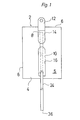
- a disposable packaging is generally designated, the outer shape of which, at least during transport and storage, is determined by a flat rectangular box 4 made of cardboard.
- the box 4 has elongated openings 8 and 10 on its broad side, designated 5, and a hanging tab 12, which is separated from the broad side 5 along a perforation line 14 formed in it and the opening 8 and is bent through 180 °.
- a strip (not shown) torn off along the perforation line 16 closes the opening 10 during transport and storage.
- the box 4 contains a lining in the form of a bag 18 made of film material which delimits a storage space 20 (FIG. 2).
- the film material preferably consists of several layers and has at least one plastic layer and at least one Metal layer, the latter forming a diffusion barrier and the plastic layer forming the innermost layer on the bag 18.
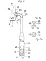
- a connector 22 is connected to the bag 18 in a liquid-tight manner, to which a hose 24 made of rubber-elastic material is connected by means of a coupling piece 26 molded onto the latter.
- the coupling piece 26 is held on the socket 22 by a safety ring 28.
- the tube 24 is laid inside the box 4 before the box 4 is opened, approximately as shown in dash-dotted lines in FIG. 1. Accordingly, this hose, although it forms part of the disposable packaging, does not hinder transport and storage thereof.
- the hose 24 can be pulled out of the box 4 through the opening 10 so that it assumes the position shown in FIG. 1 (in solid lines) and FIG. 2.
- the hose 24 contains a removal channel 30, which is connected to the storage space 20 via the connection piece 22, and a metering chamber 32 in a hose section 34 with a diameter which is expanded in comparison with the diameter of the hose in its remaining length.
- the tube 24 delimits an outlet 36 at the end of the removal channel 30 and contains an insert 38 arranged between the metering chamber 32 and the outlet 36.
- the insert 38 comprises a pin 40 with a circular cross-section and a rounded profile, a likewise circular foot part 42 with a larger diameter than the pin 40, the foot part having openings 44 distributed around its circumference, and a shaft 46 of reduced diameter compared to the pin 40 , which rigid the latter with the foot part 42 connects.
- the pin 40 forms a pressure relief valve in that the hose grips the pin with a prestress.
- the pin 40 is secured against displacement in the hose 24 by virtue of the fact that the base part 44 is overlapped by the hose 24 with greater prestress than the pin 40 due to its larger outside diameter.
- the hose is lifted off the surface of the pin when the pressure generated has exceeded a level determined by the prestressing of the hose.
- Liquid contained in the metering chamber 32 can therefore flow freely along the shaft 46 and through the openings 44 in the foot part 42 to the outlet 36.
- the greater pre-tensioning of the hose on the foot part 42 prevents the insert 38 from shifting before the pressure relief valve 50 has opened.
- the response pressure of the pressure relief valve 50 between 1.5-6.0 bar.
- the foot part 44 can be gripped by a bead (not shown) which is provided on the inside of the hose in the vicinity of the outlet 36 in order to secure the insert 38.
- the removal device shown schematically in FIG. 3 one-way packaging of the type explained above is shown in the ready-to-remove state.
- the removal device comprises a base plate 60, which may have a cooling device, not shown, and on which the disposable packaging 2 is fastened to a hook 62 by means of the hanging tab 12.
- the removal device according to the exemplary embodiment shown also includes a monitoring device, which puts a hose 24 above the Ab Pin 74 74 overlapping, for example capacitive transmitter element 82.
- the outlet 36 of the disposable packaging 2 is directed against a removal station (not shown) of the removal device, at which a drinking vessel, e.g. a mug is set up.
- a drinking vessel e.g. a mug
- a drinking vessel e.g. a mug
- organs discharge at the removal station e.g. for hot water, milk and / or cream and sugar.
- the dispenser works in the manner described below.
- the pressure piston In the initial position of the removal device, the pressure piston is retracted relative to the intermediate position shown in FIG. 3, to the extent that the pinch pin 74 has released the hose 24.
- the removal channel 30 is therefore open between the storage space 20 and the metering chamber 32.
- the metering chamber 32 is filled accordingly under the constant internal pressure prevailing in the storage space 20, which is applied by the pressure generating plate 68 and is preferably between 0.1 and 0.3 bar. Due to its considerably higher response pressure, the pressure relief valve 50 cannot, however, discharge any liquid in the direction of the outlet 36.
- the pressure piston 72 Following the filling process of the metering chamber 32, the pressure piston 72 is displaced in the direction of the counter plate 66 by the drive means 80. In this case, the position shown in FIG.
- the pressure generating plate 68 has an elastic compensation layer 69 on its side facing the base plate 60.
- the compensation layer 69 is therefore able to compensate for unevenness to a limited extent, for example in the area of the box edges. As a result, even if the box 4 is collapsed is not forming pockets in the bag from which the liquid cannot be squeezed out.
- the transmitter element 82 responds to the monitoring device and blocks e.g. the drive means 80.
- the ejection piston 72 therefore remains in the starting position.
- the acceptance of money can be blocked by the monitoring device and can remain blocked until the donor element 82 detects the presence of liquid again, e.g. after the empty disposable packaging 2 has been replaced by a full packaging.
- the removal device for receiving a number of disposable packs 2 in a position ready for removal, with at least the outlets 36 of two packs being directed at the same removal point.
- the monitoring device can initiate the removal from the second package when the first package is exhausted.
- the removal device can also have one or more cooled slots for disposable packaging in order to keep the contents fresh during the consumption time.
- the disposable packaging can be exchanged in a removal device in a very simple manner and without unintentional leakage of the contents of the bag, since the pressure relief valve 50 remains closed except when there is an intentional emptying and no connections with liquid leading lines must be manufactured.
- the removal device can be designed to be adjustable in relation to the portion size or amount of liquid which is dispensed during a removal process.
- the head 73 provided on the squeezing piston 72 is not rigid, but e.g. is pivotable about a horizontal axis running at its upper edge and is arranged adjustable in its pivoting position. Corresponding to the inclination of the head 73, a larger or smaller amount of liquid is pressed out of the metering chamber 32 accordingly. The same effect can be achieved in that the stroke of the pressure piston 72 is changed so that it moves closer or less close to the counter plate 66.
- the design of the removal channel 30 in a hose made of rubber-elastic material not only has the advantage that its elasticity can not only be used for the function of the pressure relief valve, but also allows the hose to be reliably sealed off by the pinch pin in order to prevent liquid from flowing back to prevent the metering chamber 4 when squeezing the same.
- elastic behavior is not advantageous. If the emptying pressure in the bag is not constant, the volume of the dosing chamber can change accordingly and lead to dosing errors. It is therefore advantageous to design the hose in the part delimiting the metering chamber 32 as flexible but inelastic or less elastic than in the other parts.
- the position of the parts shown in FIG. 3 can also itself represent the starting position, the metering chamber 32 being still empty, since the pinch pin 74 has not yet released the removal channel 30. This has the advantage that the liquid is retained in the area cooled by the base plate 60 until a new removal takes place.
Landscapes
- Mechanical Engineering (AREA)
- Physics & Mathematics (AREA)
- Fluid Mechanics (AREA)
- General Physics & Mathematics (AREA)
- Engineering & Computer Science (AREA)
- Packages (AREA)
- Apparatus For Making Beverages (AREA)
- Basic Packing Technique (AREA)
- Beverage Vending Machines With Cups, And Gas Or Electricity Vending Machines (AREA)
- Filling Of Jars Or Cans And Processes For Cleaning And Sealing Jars (AREA)
- Containers And Packaging Bodies Having A Special Means To Remove Contents (AREA)
- Coating Apparatus (AREA)
- Tea And Coffee (AREA)
- Containers And Plastic Fillers For Packaging (AREA)
- Devices For Dispensing Beverages (AREA)
- Cartons (AREA)
- Extraction Or Liquid Replacement (AREA)
- Loading And Unloading Of Fuel Tanks Or Ships (AREA)
Priority Applications (1)
| Application Number | Priority Date | Filing Date | Title |
|---|---|---|---|
| AT81110129T ATE19495T1 (de) | 1980-12-08 | 1981-12-04 | Einwegverpackung fuer fluessigkeiten. |
Applications Claiming Priority (2)
| Application Number | Priority Date | Filing Date | Title |
|---|---|---|---|
| CH9035/80A CH651519A5 (de) | 1980-12-08 | 1980-12-08 | Einwegverpackung fuer fluessigkeiten und einrichtung zur entnahme von fluessigkeiten aus dieser. |
| CH9035/80 | 1980-12-08 |
Publications (3)
| Publication Number | Publication Date |
|---|---|
| EP0054232A2 true EP0054232A2 (fr) | 1982-06-23 |
| EP0054232A3 EP0054232A3 (en) | 1982-10-20 |
| EP0054232B1 EP0054232B1 (fr) | 1986-04-30 |
Family
ID=4347599
Family Applications (1)
| Application Number | Title | Priority Date | Filing Date |
|---|---|---|---|
| EP81110129A Expired EP0054232B1 (fr) | 1980-12-08 | 1981-12-04 | Récipient jetable pour liquides |
Country Status (14)
| Country | Link |
|---|---|
| US (1) | US4520948A (fr) |
| EP (1) | EP0054232B1 (fr) |
| JP (1) | JPS57153895A (fr) |
| AT (1) | ATE19495T1 (fr) |
| AU (1) | AU542491B2 (fr) |
| BR (1) | BR8107926A (fr) |
| CA (1) | CA1180567A (fr) |
| CH (1) | CH651519A5 (fr) |
| DE (2) | DE3174528D1 (fr) |
| DK (1) | DK152704C (fr) |
| ES (1) | ES507764A0 (fr) |
| IE (1) | IE52533B1 (fr) |
| MX (1) | MX154542A (fr) |
| ZA (1) | ZA818327B (fr) |
Cited By (2)
| Publication number | Priority date | Publication date | Assignee | Title |
|---|---|---|---|---|
| EP0129131A3 (fr) * | 1983-06-10 | 1986-02-05 | Jacobs Beverage Systems AG | Emballage sans retour pour fluide |
| WO2011137498A1 (fr) | 2010-05-07 | 2011-11-10 | Tatjana Yazgheche | Dispositif de dosage modulaire et distributeur comprenant un tel dispositif de dosage |
Families Citing this family (40)
| Publication number | Priority date | Publication date | Assignee | Title |
|---|---|---|---|---|
| US4645094A (en) * | 1983-04-26 | 1987-02-24 | Calgon Corporation | Photo-electric controlled dispenser |
| DE3440367A1 (de) * | 1984-11-05 | 1986-05-07 | Hch. Sieger Papier- und Wellpappenwerke KG, 5040 Brühl | Verpackungsbehaelter und verfahren zu seiner herstellung und herrichtung |
| AU590983B2 (en) * | 1987-10-14 | 1989-11-23 | Unro Teknik Ab | A device for dispensing flowing substances |
| US4899911A (en) * | 1988-08-02 | 1990-02-13 | Multimix Systems, Inc. | Apparatus and method for dispensing an individual beverage serving |
| US5025953A (en) * | 1988-10-17 | 1991-06-25 | Doundoulakis George J | Deformable beverage containers for preserving carbonation |
| US5195661A (en) * | 1989-11-28 | 1993-03-23 | Gas-O-Haul Incorporated | Composite fluid carrier |
| US5526958A (en) * | 1991-06-17 | 1996-06-18 | Kueppersbusch; Gerd | Tube box |
| US5433351A (en) * | 1992-05-01 | 1995-07-18 | Misuzuerie Co., Ltd. | Controlled liquid dispensing apparatus |
| CA2146102C (fr) * | 1995-03-31 | 2000-07-25 | Hermann Ophardt | Sac distributeur de fluide |
| US6209781B1 (en) | 1999-02-26 | 2001-04-03 | Liberty Carton Co. | Disposable, foldable container |
| MXPA03003556A (es) | 2000-10-23 | 2005-04-11 | Medical Instill Tech Inc | Distribuidor de fluido que tiene un frasco rigido y camara de aire interna flexible. |
| US7331944B2 (en) | 2000-10-23 | 2008-02-19 | Medical Instill Technologies, Inc. | Ophthalmic dispenser and associated method |
| US7798185B2 (en) | 2005-08-01 | 2010-09-21 | Medical Instill Technologies, Inc. | Dispenser and method for storing and dispensing sterile food product |
| US6732889B2 (en) | 2002-02-06 | 2004-05-11 | Ishai Oren | Pouring spout for liquid containers, and liquid containers constructed therewith |
| CA2495582C (fr) | 2002-08-13 | 2016-07-12 | Medical Instill Technologies, Inc. | Ensemble recipient et valve pour stocker et distribuer des substances, et procede associe |
| US6997219B2 (en) | 2003-05-12 | 2006-02-14 | Medical Instill Technologies, Inc. | Dispenser and apparatus and method for filling a dispenser |
| US7226231B2 (en) * | 2003-07-17 | 2007-06-05 | Medical Instill Technologies, Inc. | Piston-type dispenser with one-way valve for storing and dispensing metered amounts of substances |
| US7810677B2 (en) | 2004-12-04 | 2010-10-12 | Medical Instill Technologies, Inc. | One-way valve and apparatus and method of using the valve |
| CN101107176B (zh) * | 2004-12-04 | 2012-04-18 | 因斯蒂尔医学技术有限公司 | 柔性袋和阀的组件以及储存和分配流体的设备和方法 |
| ATE509839T1 (de) * | 2005-09-02 | 2011-06-15 | Mds Global Holding Ltd | Behälter zum ausgeben einer substanz |
| US20080041882A1 (en) * | 2006-08-08 | 2008-02-21 | Lips Jon S | Container for transporting and dispensing liquids |
| US8162180B2 (en) * | 2006-08-08 | 2012-04-24 | Lips Jon S | Container for transporting and dispensing liquids |
| US8356733B2 (en) * | 2006-09-08 | 2013-01-22 | Medical Instill Technologies, Inc. | Method for dispensing fluids |
| US8986253B2 (en) | 2008-01-25 | 2015-03-24 | Tandem Diabetes Care, Inc. | Two chamber pumps and related methods |
| US8408421B2 (en) * | 2008-09-16 | 2013-04-02 | Tandem Diabetes Care, Inc. | Flow regulating stopcocks and related methods |
| US9250106B2 (en) | 2009-02-27 | 2016-02-02 | Tandem Diabetes Care, Inc. | Methods and devices for determination of flow reservoir volume |
| US8573027B2 (en) | 2009-02-27 | 2013-11-05 | Tandem Diabetes Care, Inc. | Methods and devices for determination of flow reservoir volume |
| US8926561B2 (en) | 2009-07-30 | 2015-01-06 | Tandem Diabetes Care, Inc. | Infusion pump system with disposable cartridge having pressure venting and pressure feedback |
| WO2011140508A1 (fr) | 2010-05-07 | 2011-11-10 | Alps, Llc | Vanne pour machine distributrice et procédé associé |
| US9180242B2 (en) | 2012-05-17 | 2015-11-10 | Tandem Diabetes Care, Inc. | Methods and devices for multiple fluid transfer |
| US9555186B2 (en) | 2012-06-05 | 2017-01-31 | Tandem Diabetes Care, Inc. | Infusion pump system with disposable cartridge having pressure venting and pressure feedback |
| US9173998B2 (en) | 2013-03-14 | 2015-11-03 | Tandem Diabetes Care, Inc. | System and method for detecting occlusions in an infusion pump |
| KR20160015253A (ko) * | 2013-05-10 | 2016-02-12 | 쥬세로 인코퍼레이티드 | 착즙 시스템 및 방법 |
| EP2896332B1 (fr) * | 2014-01-15 | 2016-08-17 | De'Longhi Appliances S.r.l. | Dispositif pouvant être associé à une buse de distribution de vapeur d'une machine à café pour la production d'une boisson lactée |
| US10543652B2 (en) * | 2016-03-03 | 2020-01-28 | Fresh Press LLC | Press |
| US20170252993A1 (en) * | 2016-03-03 | 2017-09-07 | Juicero, Inc. | Juicer cartridge with coupling |
| JP6903416B2 (ja) * | 2016-10-26 | 2021-07-14 | サントリーホールディングス株式会社 | 容器収納装置及び飲料ディスペンサ |
| US20180297309A1 (en) * | 2017-04-13 | 2018-10-18 | Juicero, Inc. | Press |
| US20180297311A1 (en) * | 2017-04-13 | 2018-10-18 | Juicero, Inc. | Press |
| US20180297312A1 (en) * | 2017-04-13 | 2018-10-18 | Juicero, Inc. | Press |
Family Cites Families (14)
| Publication number | Priority date | Publication date | Assignee | Title |
|---|---|---|---|---|
| GB678480A (en) * | 1950-04-03 | 1952-09-03 | Wingfoot Corp | Package for liquids |
| US2647661A (en) * | 1950-06-26 | 1953-08-04 | Leo M Harvey | Mechanism for dispensing liquid from a plurality of supply containers |
| US3117695A (en) * | 1960-05-19 | 1964-01-14 | Inland Container Corp | Fluid dispensing container |
| CH389170A (de) * | 1961-08-22 | 1965-03-15 | Alusuisse | Verfahren zum Konstanthalten der Spiegelhöhe einer Metallschmelze |
| US3205889A (en) * | 1962-07-23 | 1965-09-14 | Abbott Lab | Parenteral fluid container and port structure |
| US3199742A (en) * | 1963-06-28 | 1965-08-10 | Hill Brothers Chem Co | Container |
| US3534771A (en) * | 1967-10-30 | 1970-10-20 | Eaton Yale & Towne | Valve assembly |
| US3811294A (en) * | 1973-02-23 | 1974-05-21 | Ebco Mfg Co | Cooler for faucet-equipped beverage containers |
| US4130224A (en) * | 1976-10-08 | 1978-12-19 | Envair, Inc. | Viscous liquid dispenser |
| EP0002987A1 (fr) * | 1977-12-30 | 1979-07-11 | Societe Generale Pour L'emballage | Procédé et machine pour la préparation sur le lieu de consommation de doses unitaires de boissons et produit utilisable dans le procédé |
| US4228926A (en) * | 1978-03-06 | 1980-10-21 | Shandon Southern Products Limited | Dispensing viscous fluids |
| DE2908654A1 (de) * | 1979-03-06 | 1980-09-11 | Rupert Mader | Verpackungselement |
| US4349133A (en) * | 1979-09-12 | 1982-09-14 | Christine William C | Dispenser and refill package |
| US4256242A (en) * | 1979-10-23 | 1981-03-17 | Christine William C | Dispenser having a roller for squeezing amounts from a tube |
-
1980
- 1980-12-08 CH CH9035/80A patent/CH651519A5/de not_active IP Right Cessation
-
1981
- 1981-12-01 ZA ZA818327A patent/ZA818327B/xx unknown
- 1981-12-03 AU AU78227/81A patent/AU542491B2/en not_active Ceased
- 1981-12-04 AT AT81110129T patent/ATE19495T1/de active
- 1981-12-04 DE DE8181110129T patent/DE3174528D1/de not_active Expired
- 1981-12-04 EP EP81110129A patent/EP0054232B1/fr not_active Expired
- 1981-12-07 DE DE8135579U patent/DE8135579U1/de not_active Expired
- 1981-12-07 DK DK539381A patent/DK152704C/da not_active IP Right Cessation
- 1981-12-07 IE IE2869/81A patent/IE52533B1/en unknown
- 1981-12-07 ES ES507764A patent/ES507764A0/es active Granted
- 1981-12-07 BR BR8107926A patent/BR8107926A/pt unknown
- 1981-12-07 CA CA000391613A patent/CA1180567A/fr not_active Expired
- 1981-12-08 JP JP56197572A patent/JPS57153895A/ja active Pending
- 1981-12-08 MX MX190491A patent/MX154542A/es unknown
- 1981-12-08 US US06/328,799 patent/US4520948A/en not_active Expired - Fee Related
Cited By (2)
| Publication number | Priority date | Publication date | Assignee | Title |
|---|---|---|---|---|
| EP0129131A3 (fr) * | 1983-06-10 | 1986-02-05 | Jacobs Beverage Systems AG | Emballage sans retour pour fluide |
| WO2011137498A1 (fr) | 2010-05-07 | 2011-11-10 | Tatjana Yazgheche | Dispositif de dosage modulaire et distributeur comprenant un tel dispositif de dosage |
Also Published As
| Publication number | Publication date |
|---|---|
| ATE19495T1 (de) | 1986-05-15 |
| DE8135579U1 (de) | 1983-08-25 |
| IE52533B1 (en) | 1987-12-09 |
| AU542491B2 (en) | 1985-02-21 |
| DE3174528D1 (en) | 1986-06-05 |
| ES8300460A1 (es) | 1982-11-01 |
| JPS57153895A (en) | 1982-09-22 |
| CA1180567A (fr) | 1985-01-08 |
| DK152704B (da) | 1988-04-25 |
| DK539381A (da) | 1982-06-09 |
| BR8107926A (pt) | 1982-09-14 |
| MX154542A (es) | 1987-09-28 |
| AU7822781A (en) | 1982-06-17 |
| EP0054232B1 (fr) | 1986-04-30 |
| US4520948A (en) | 1985-06-04 |
| ES507764A0 (es) | 1982-11-01 |
| CH651519A5 (de) | 1985-09-30 |
| IE812869L (en) | 1982-06-08 |
| ZA818327B (en) | 1982-10-27 |
| DK152704C (da) | 1988-09-19 |
| EP0054232A3 (en) | 1982-10-20 |
Similar Documents
| Publication | Publication Date | Title |
|---|---|---|
| EP0054232B1 (fr) | Récipient jetable pour liquides | |
| DE69509456T2 (de) | Flüssigkeitsabgabebeutel mit venturiförmiger austrittsöffnung | |
| DE69812600T2 (de) | Stopfen und formveränderlicher behälter mit einem solchen stopfen | |
| EP2512302B1 (fr) | Dispositif de préparation d'une boisson et capsule | |
| DE3210668C2 (fr) | ||
| DE102007024106B4 (de) | Füllsystem | |
| EP2528851B1 (fr) | Dispositif et procédé de dosage de liquides | |
| DE69400865T2 (de) | Beutel zur abgabe vob flüssigkeit mit mehreren abgabeöffnungen | |
| DE202014001720U1 (de) | Spender | |
| DE212008000119U1 (de) | Dosiergerät zur Dosierung eines flüssigen Produktes | |
| CH645858A5 (de) | Verpackung fuer pulverfoermiges material. | |
| DE3245943C2 (de) | Auslaßventil zur schaumarmen Abgabe loser Frischmilch in abgemessenen Mengen an den Verbraucher | |
| WO2000055071A1 (fr) | Recipient en plastique et element doseur correspondant muni d'un systeme de fermeture | |
| DE1773420B1 (de) | Dosiervorrichtung | |
| EP1108656B1 (fr) | Récipient pour plusieurs composants pour stocker et distribuer des produits liquides ou pâteux | |
| DE8138627U1 (de) | Einrichtung zur entnahme von fluessigkeiten aus einer einwegverpackung | |
| DE2602832A1 (de) | Kapsel fuer die konfektionierung von unter der einwirkung einer unter druck stehenden fluessigkeit zu verteilenden produkten | |
| DE4139534C2 (de) | Quetschflasche mit Dosiervorrichtung | |
| EP1590586B1 (fr) | Soupape pour le transvasement en cadence de produits d'un recipient d'alimentation dans des recipients d'emballage | |
| EP3839445A1 (fr) | Dispositif de dosage ainsi que procédé de distribution d'une substance coulante | |
| DE4022616A1 (de) | Flexibler beutel zur aufnahme von fluessigkeiten | |
| DE3515024C1 (de) | Vorrichtung zur Dosierung einer Flüssigkeit | |
| DE7924833U1 (de) | Vorrichtung zum Dosieren von Fluessigkeiten | |
| AT336193B (de) | Vorrichtung zur dosierbaren abgabe von flussigkeit | |
| DE2060910C3 (de) | Getränkedosiervorrichtung mit einem flüssigkeitsdichten Beutel |
Legal Events
| Date | Code | Title | Description |
|---|---|---|---|
| PUAI | Public reference made under article 153(3) epc to a published international application that has entered the european phase |
Free format text: ORIGINAL CODE: 0009012 |
|
| AK | Designated contracting states |
Designated state(s): AT BE DE FR GB NL SE |
|
| PUAL | Search report despatched |
Free format text: ORIGINAL CODE: 0009013 |
|
| AK | Designated contracting states |
Designated state(s): AT BE DE FR GB NL SE |
|
| 17P | Request for examination filed |
Effective date: 19830326 |
|
| RAP1 | Party data changed (applicant data changed or rights of an application transferred) |
Owner name: JACOBS BEVERAGE SYSTEMS AG |
|
| GRAA | (expected) grant |
Free format text: ORIGINAL CODE: 0009210 |
|
| RAP1 | Party data changed (applicant data changed or rights of an application transferred) |
Owner name: JACOBS SUCHARD AG |
|
| AK | Designated contracting states |
Kind code of ref document: B1 Designated state(s): AT BE DE FR GB NL SE |
|
| REF | Corresponds to: |
Ref document number: 19495 Country of ref document: AT Date of ref document: 19860515 Kind code of ref document: T |
|
| ET | Fr: translation filed | ||
| REF | Corresponds to: |
Ref document number: 3174528 Country of ref document: DE Date of ref document: 19860605 |
|
| PGFP | Annual fee paid to national office [announced via postgrant information from national office to epo] |
Ref country code: AT Payment date: 19861218 Year of fee payment: 6 |
|
| PGFP | Annual fee paid to national office [announced via postgrant information from national office to epo] |
Ref country code: NL Payment date: 19861231 Year of fee payment: 6 |
|
| PLBE | No opposition filed within time limit |
Free format text: ORIGINAL CODE: 0009261 |
|
| STAA | Information on the status of an ep patent application or granted ep patent |
Free format text: STATUS: NO OPPOSITION FILED WITHIN TIME LIMIT |
|
| 26N | No opposition filed | ||
| PG25 | Lapsed in a contracting state [announced via postgrant information from national office to epo] |
Ref country code: NL Effective date: 19880701 |
|
| NLV4 | Nl: lapsed or anulled due to non-payment of the annual fee | ||
| PG25 | Lapsed in a contracting state [announced via postgrant information from national office to epo] |
Ref country code: DE Effective date: 19880901 |
|
| PG25 | Lapsed in a contracting state [announced via postgrant information from national office to epo] |
Ref country code: GB Effective date: 19881204 Ref country code: AT Effective date: 19881204 |
|
| PG25 | Lapsed in a contracting state [announced via postgrant information from national office to epo] |
Ref country code: SE Effective date: 19881205 |
|
| PG25 | Lapsed in a contracting state [announced via postgrant information from national office to epo] |
Ref country code: BE Effective date: 19881231 |
|
| BERE | Be: lapsed |
Owner name: JACOBS SUCHARD A.G. Effective date: 19881231 |
|
| GBPC | Gb: european patent ceased through non-payment of renewal fee | ||
| PG25 | Lapsed in a contracting state [announced via postgrant information from national office to epo] |
Ref country code: FR Free format text: LAPSE BECAUSE OF NON-PAYMENT OF DUE FEES Effective date: 19890831 |
|
| REG | Reference to a national code |
Ref country code: FR Ref legal event code: ST |
|
| EUG | Se: european patent has lapsed |
Ref document number: 81110129.4 Effective date: 19891215 |