EP0054321A1 - Procédé et appareil pour exécuter des mesures sur bandes flexibles minces - Google Patents
Procédé et appareil pour exécuter des mesures sur bandes flexibles minces Download PDFInfo
- Publication number
- EP0054321A1 EP0054321A1 EP81201287A EP81201287A EP0054321A1 EP 0054321 A1 EP0054321 A1 EP 0054321A1 EP 81201287 A EP81201287 A EP 81201287A EP 81201287 A EP81201287 A EP 81201287A EP 0054321 A1 EP0054321 A1 EP 0054321A1
- Authority
- EP
- European Patent Office
- Prior art keywords
- tape material
- measuring
- guide
- duct
- guide surfaces
- Prior art date
- Legal status (The legal status is an assumption and is not a legal conclusion. Google has not performed a legal analysis and makes no representation as to the accuracy of the status listed.)
- Granted
Links
- 239000000463 material Substances 0.000 title claims abstract description 104
- 238000005259 measurement Methods 0.000 title claims abstract description 23
- 238000000034 method Methods 0.000 title claims description 5
- XUIMIQQOPSSXEZ-UHFFFAOYSA-N Silicon Chemical compound [Si] XUIMIQQOPSSXEZ-UHFFFAOYSA-N 0.000 claims description 3
- 229910052710 silicon Inorganic materials 0.000 claims description 3
- 239000010703 silicon Substances 0.000 claims description 3
- 239000004065 semiconductor Substances 0.000 claims description 2
- 239000011888 foil Substances 0.000 description 9
- 238000005452 bending Methods 0.000 description 6
- 238000010276 construction Methods 0.000 description 2
- 230000035945 sensitivity Effects 0.000 description 2
- 239000003990 capacitor Substances 0.000 description 1
- 230000002349 favourable effect Effects 0.000 description 1
- 230000003993 interaction Effects 0.000 description 1
- 238000004519 manufacturing process Methods 0.000 description 1
- 238000005086 pumping Methods 0.000 description 1
- 239000007787 solid Substances 0.000 description 1
Images



Classifications
-
- G—PHYSICS
- G01—MEASURING; TESTING
- G01L—MEASURING FORCE, STRESS, TORQUE, WORK, MECHANICAL POWER, MECHANICAL EFFICIENCY, OR FLUID PRESSURE
- G01L5/00—Apparatus for, or methods of, measuring force, work, mechanical power, or torque, specially adapted for specific purposes
- G01L5/04—Apparatus for, or methods of, measuring force, work, mechanical power, or torque, specially adapted for specific purposes for measuring tension in flexible members, e.g. ropes, cables, wires, threads, belts or bands
- G01L5/08—Apparatus for, or methods of, measuring force, work, mechanical power, or torque, specially adapted for specific purposes for measuring tension in flexible members, e.g. ropes, cables, wires, threads, belts or bands using fluid means
-
- G—PHYSICS
- G01—MEASURING; TESTING
- G01B—MEASURING LENGTH, THICKNESS OR SIMILAR LINEAR DIMENSIONS; MEASURING ANGLES; MEASURING AREAS; MEASURING IRREGULARITIES OF SURFACES OR CONTOURS
- G01B13/00—Measuring arrangements characterised by the use of fluids
- G01B13/02—Measuring arrangements characterised by the use of fluids for measuring length, width or thickness
- G01B13/06—Measuring arrangements characterised by the use of fluids for measuring length, width or thickness for measuring thickness
-
- G—PHYSICS
- G11—INFORMATION STORAGE
- G11B—INFORMATION STORAGE BASED ON RELATIVE MOVEMENT BETWEEN RECORD CARRIER AND TRANSDUCER
- G11B15/00—Driving, starting or stopping record carriers of filamentary or web form; Driving both such record carriers and heads; Guiding such record carriers or containers therefor; Control thereof; Control of operating function
- G11B15/60—Guiding record carrier
- G11B15/605—Guiding record carrier without displacing the guiding means
- G11B15/607—Pneumatic guiding
-
- G—PHYSICS
- G11—INFORMATION STORAGE
- G11B—INFORMATION STORAGE BASED ON RELATIVE MOVEMENT BETWEEN RECORD CARRIER AND TRANSDUCER
- G11B15/00—Driving, starting or stopping record carriers of filamentary or web form; Driving both such record carriers and heads; Guiding such record carriers or containers therefor; Control thereof; Control of operating function
- G11B15/60—Guiding record carrier
- G11B15/62—Maintaining desired spacing between record carrier and head
- G11B15/64—Maintaining desired spacing between record carrier and head by fluid-dynamic spacing
Definitions
- the invention relates to a device for carrying out measurements on a thin flexible tape material, which device comprises at least one pair of guide elements which are spaced from each other and on adjacent sides are provided with guide surfaces which extend substantially parallel to each other and between which a guide channel for the tape material is formed, in which guide surfaces supply ducts terminate for supplying to both sides of a tape material in the guide channel a pressurized gaseous medium by means of which the tape material can be guided in the longitudinal direction in the guide channel along a path which is substantially parallel to and spaced from the guide surfaces, and in each of which guide surfaces a termination of at least one measuring duct is situated, said measuring-duct termination or each measuring-duct termination in one guide surface being arranged at least substantially directly opposite the measuring-duct termination or an associated one of the measuring-duct terminations in the other guide surface and forming therewith a pair of measuring-duct terminations in the other guide surface and forming therewith a pair of measuring-duct terminations, and the measuring ducts communicating with at least one pressure transducer.
- a device of this type is known from British Patent Specification 1.461.248.
- the web material is guided between two guide surfaces, the medium pressure on each side being determined continuously.
- pressure variations occur on both sides cf the material, which variations are converted into electrical quantities, which are added to form a sum quantity from which the local thickness of the web material is derived continuously
- Such a method is suitable for thickness measurements only, because the measuring means are adapted for determining sum quantities only.
- the flat shape of the guide surfaces does not permit the use of measurements of a different type.
- the guide surfaces have correspondingly_ curved shapes
- the tape material can be guided in the guide channel along a curved path
- the pressure transducer is connected to measuring means for measuring the pressure difference on both sides of the tape material in such a way that the device is capable of measuring local tensile stresses in the tape material.
- the device in accordance with the invention enables tensile stresses in a thin flexible foil or tape material to be measured, the curved path of the tape material in the guide channel ensuring that the material does not touch the guide surfaces, which would give rise to additional friction and thus a measuring error.
- the device in accordance with the invention it is possible to gain an insight into the various parameters which are of importance for the transport of such a thin flexible tape material.
- United States Patent Specification 3,715,521 reveals a device employing two mutually spaced guide elements, in whose curved guide surfaces medium supply ducts terminate.
- one of the guide elements also forms a magnetic head.
- the medium supply ducts terminate in the guide surfaces on both sides of each termination of a measuring duct.
- the termination of each measuring duct is situated in the respective guide surface directly opposite a central portion of the curved path of the tape material and this ensures a satisfactory pressure build-up in the guide channel and minimizes the influence of disturbing factors on the measurement.
- Another embodiment of a device in accordance with the invention is characterized in that in the lateral direction of the tape material the terminations of a pair of measuring ducts are situated in the guide surfaces directly opposite the centre of the tape material. In this way it is possible to measure the tensile or tractive force of the tape material.
- Further embodiment of the device in accordance with the invention is characterized in that in the lateral direction of the tape material the terminations of at least two pairs of measuring ducts are situated symmetrically in the guide surfaces relative to the centre of the tape material. These steps make it possible to measure the tensile force in the tape material and to determine the bending moment in the plane of the material.
- the terminations of one pair of measuring ducts are situated directly opposite the centre of the tape material and the terminations of at least two further pairs of measuring ducts are situated symmetrically in the guide surfaces relative to the centre of the tape material.
- each guide surface the terminations of five measuring ducts are situated, which terminations are arranged in a regularly distributed manner. In this way the distribution of tension in the tape material can be determined wiht even greater accuracy and an even more accurate determination of the tensile force, bending moment and torsional moment is possible.
- the device comprises two pairs of guide elements, which are rigidly connected to each other and which form guide channels which adjoin each other and are arranged to guide the tape material along an undulating path.
- the device simultaneous measurements to be carried out at two locations which are spaced from each other in the longitudinal direction of the tape material.
- the measured variation of the moment is a measure of the transverse force in the tape material.
- the pressure transducer is of the semiconductor type with an integrated silicon diaphragm. As a result of this; the device may have small dimensions and a high pressure sensitivity.
- a method of carrying out measurements on a thin flexible tape material with the aid of a device in accordance with the invention in which a pressurized gaseous medium is fed into the guide channel is characterized in that the device is arranged on an apparatus which moves the tape material past tape guides in the longitudinal direction, the tape material is fed between the guide surfaces and subsequently, during transport of the tape material, the pressure difference on both sides of the tape material is determined with the pressure transducer and measuring means, from which difference a parameter which is important for the tape transport is derived with the aid of the measuring means, which parameter also provides information on parts on the apparatus which are of importance for the transport of the tape material, such as the positioning of the tape guides, by means of which information and adjustment, such as a correction of the position of the tape guides, may be applied.
- This method provides a comparatively rapid control with high precision of equipment employing tape material such as video and audio magnetic tape apparatus.
- the device 1 shown in Figure 1 comprises guide elements 2 and 3, which are arranged on a fitting surface 4.
- the surface 4 enables the device 1 to be positioned accurately relative to the other parts of an apparatus, of which only a frame plate 5 with the surface 4 is shown.
- the apparatus is intended for the transport of foil on tape material 6 and for this purpose it is provided with.
- tape guides which guide the-material in a manner, not shown, and with transport means for the transport of the tape material.
- the tape material is of a thin flexible type, which in the embodiment shown is constituted by a magnetic tape intended for recording and/or reading signals.
- the apparatus is also suitable for, in addition to the magnetic tape transport, recording and/or reading magnetic signals on the tape material 6.
- the two guide elements are spaced from each other and are provided on adjacent sides with correspondingly curved guide surfaces 7 and 8 respectively which extend substantially parallel to each other. Between the guide surfaces 7 and 8 a guide channel 9 for the tape material 6 is formed. It is to be noted that in Figure 2 the distance between the surfaces 7 and 8 is shown on an enlarged scale for a correct representation of the channel 9.
- the guide element 2 comprises portions 10 and 11, whilst the guide element 3 comprises portions 12 and 13.. Each portion is constituted by a solid block of material, two of the sides of the portions 10 and 11 constituting the guide surface 7 and two of the sides of the portions 12 and 13 constituting the guide surface 8.
- the guide surfaces 7 and 8 are curved in a regular manner, the guide surfaces in the present embodiment each forming a part-cylindrical surface having a radius designated by the reference numeral 14 in Figure 2, which radius is approximately 12 mn in the present embodiment. As will be described in more detail. It is alternatively possible to adapt other values for the radius 14.
- the distance between the two guide surfaces, which distance is indicated by the reference numeral 15 in Figure 2, is 0,043 mm in the present embodiment. It is emphasized that, depending on the construction of the various parts of the device it is also possible to use a different distance.
- main supply ducts 16 for a gaseous medium are formed, whose axes are parallel to the axes of curvature of the guide surfaces 7 and 8.
- the ducts 16, as is shown in Figure 1 extend to the exterior of the device 1 and, in a manner not shown, are connected to a pumping device which pumps a pressurized gaseous medium, in the present embodiment air, into the main supply duct 16.
- medium supply ducts 17 are connected to the main supply ducts 16 in the portions 10, 11, 12 and 13 of the guide elements 2 and 3.
- each portion comprises 6 medium supply ducts 17, which extend parallel to each other and which terminate in the guide surfaces 7 and 8 respectively.
- the location of these terminations in the portions 10, 11 and 12, 13 respectively is mirror inverted relative to a plane through a control part of the guide channel.
- the supply ducts 17 in said portions are arranged so that each termination in the guide surface 7 of the guide element 2 is situated directly opposite one of the terminations in the guide surface 8 of the guide element 3 and forms therewith a pair of terminations.
- the portions of the guide elements are secured to each other by means of bolts 18.
- the two guide elements 2 and 3 are rigidly connected to each other in a manner not shown.
- a prestressed air bearina This air bearing enables the tape material to be guided in rigid form and without friction so that the tape material is not influenced during a measurement.
- the portions 10 and 12 each have a substantially L-shaped recess 24 in their inner upright side walls, which recess extends from the upper side of the respective portion to a point near the guide surface 7 or 8 respectively.
- a pressure transducer 19 is accommodated, which is suitably constructed in a manner as described in the Applicants Netherlands Patent Specification 162, 254 (PHN 3699).
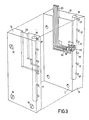
- this pressure transducer For converting mechanical tensile stresses into electric measurement signals this pressure transducer comprises an integrated silicon diaphragm 20. It is constructed so that it occupies only a small space. Moreover, this pressure transducer has a high sensitivity to pressure. As is shown in Figures 2 and 3, the end of a measuring duct 21 is situated at the location of the diaphragm, a termination 22 of said duct being disposed in the respective guide surface directly opposite a central portion of the curved path of the tape material 6. Viewed in Figures 3 and 4, the termination, seen in the lateral direction of the tape material, is situated at approxiamately equal distances from the adjacent terminations of the medium supply ducts 17.
- the pressure transducer 19 is connected to an associated p.c. board 23, whose end which extends beyond the respective guide element 2 or 3 is shown in Figure 1.
- a recess 24 similar to the recesses 24 in the portions 10 and 12 of the guide elements is formed in each of the portions 11 and 13.
- the p.c. boards are connected to measuring means 25 outside the guide elements, which means are only represented schematically for the sake of clarity.
- the terminations 22 of the pair of measuring ducts 21 in the guide elements 2 and 3 are disposed at least substantially directly opposite each other, as a result of which the pressure transducers 19 on both sides of the tape material only determine the locally prevailing pressure.
- the terminations of the pair of measuring ducts 21 are situated in the guide surfaces 2 and 3 directly opposite the centre of the tape material 6.
- This embodiment is also schematically represented in Figure 6.
- Nxx the resulting normal stress in the tape material, expressed in N/mm
- R the radius of curvature of the air bearing, designated by the reference numeral 14 in Figure 2.
- a calibration measurement is carried out, which measurement yields a calibration constant X .
- the resulting normal stress Nxx thus found is substantially independent of the distribution of the normal stress in a cross-section of the tape material, so that the present measurement is also suitable for use in the case of a non-linear distribution.
- the graphical representation of N in Figure 6 is based on a situation in which a constant tensile force N occurs, i.e. for which the moment is zero and for which the tape material is not twisted.
- the indication 1/2 b refers to half the width of the tape material.
- a second embodiment of a device in accordance with the invention as is represented schematically in Figure 7, instead of one pair there are provided two pairs of measuring ducts, the terminations of which are situated symmetrically in the guide surfaces 7 and 8 relative to the centre of the tape material 6.
- the respective pressure difference ⁇ p 1 and ⁇ p 2 at two locations on both sides of the foil or tape material can be measured.
- a third embodiment of the device in accordance with the invention which is represented schematically in Figure 8, it is alternatively possible to arrange the terminations of one pair of measuring ducts, in the lateral direction of the foil on tape material, directly opposite the centre of the tape material and the termin- - ations of at least two further pairs of measuring ducts symmetrically in the guide surfaces relative to the centre of the tape material.
- the tensile force N and the bending moment M can again be determined as follows:
- ⁇ P represents the pressure difference in the centre of the tape material
- ⁇ p 1 and ⁇ p 2 represent the values of the pressure difference at a distance from the centre.
- two pairs of guide elements 26, 27 and 28, 29 are rigidly connected to each other and are constructed so that the guide channels formed by the pairs of guide elements adjoin each other and guide the tape material along an undulating path.
- said undulating path is a sinusoid.
- a continuous cavity 30 is formed, which prevents interaction between the guide channels.
- the cavity 30 extends parallel to the axes of curvature of the guide surfaces.
- the cavity 30 measures approximately 1 by 4 mm.
- measurements at two locations spaced fran one another in the longitudinal direction of the foil on tape are possible, thereby enabling the bending moment at two locations to be determined.
- the variation of the moment between the two measuring locations is a measure of the transverse force Q (see Figure 5).
- measuring ducts communicates with one pressure transducer, which transducer may be situated in a central part of the device.
Landscapes
- Physics & Mathematics (AREA)
- General Physics & Mathematics (AREA)
- Length Measuring Devices With Unspecified Measuring Means (AREA)
- Investigating Strength Of Materials By Application Of Mechanical Stress (AREA)
- Force Measurement Appropriate To Specific Purposes (AREA)
- Registering, Tensioning, Guiding Webs, And Rollers Therefor (AREA)
- Advancing Webs (AREA)
- Manufacturing Of Magnetic Record Carriers (AREA)
- Controlling Rewinding, Feeding, Winding, Or Abnormalities Of Webs (AREA)
Priority Applications (1)
| Application Number | Priority Date | Filing Date | Title |
|---|---|---|---|
| AT81201287T ATE10033T1 (de) | 1980-12-11 | 1981-11-20 | Verfahren und vorrichtung zum ausfuehren von messungen an flexiblen duennen bandmaterialien. |
Applications Claiming Priority (2)
| Application Number | Priority Date | Filing Date | Title |
|---|---|---|---|
| NL8006719A NL8006719A (nl) | 1980-12-11 | 1980-12-11 | Inrichting voor het verrichten van metingen aan dun flexibel bandmateriaal, alsmede werkwijze voor het verrichten van metingen met behulp van de inrichting. |
| NL8006719 | 1980-12-11 |
Publications (2)
| Publication Number | Publication Date |
|---|---|
| EP0054321A1 true EP0054321A1 (fr) | 1982-06-23 |
| EP0054321B1 EP0054321B1 (fr) | 1984-10-24 |
Family
ID=19836315
Family Applications (1)
| Application Number | Title | Priority Date | Filing Date |
|---|---|---|---|
| EP81201287A Expired EP0054321B1 (fr) | 1980-12-11 | 1981-11-20 | Procédé et appareil pour exécuter des mesures sur bandes flexibles minces |
Country Status (7)
| Country | Link |
|---|---|
| US (1) | US4425809A (fr) |
| EP (1) | EP0054321B1 (fr) |
| JP (1) | JPS57122330A (fr) |
| AT (1) | ATE10033T1 (fr) |
| CA (1) | CA1168904A (fr) |
| DE (1) | DE3166868D1 (fr) |
| NL (1) | NL8006719A (fr) |
Cited By (3)
| Publication number | Priority date | Publication date | Assignee | Title |
|---|---|---|---|---|
| DE4428078A1 (de) * | 1994-08-09 | 1996-02-15 | Froehling Josef Gmbh | Verfahren und Einrichtung zum Messen von Bandspannungen |
| US8447413B2 (en) | 2008-04-29 | 2013-05-21 | Medtronic, Inc. | Configuring stimulation therapy using stimulation intensity |
| US9764147B2 (en) | 2009-04-24 | 2017-09-19 | Medtronic, Inc. | Charge-based stimulation intensity programming with pulse amplitude and width adjusted according to a function |
Families Citing this family (4)
| Publication number | Priority date | Publication date | Assignee | Title |
|---|---|---|---|---|
| US4968386A (en) * | 1988-05-10 | 1990-11-06 | Union Camp Corporation | Apparatus for determining amplitude and frequency of web flutter |
| US4992142A (en) * | 1988-05-10 | 1991-02-12 | Union Camp Corporation | Method for determining amplitude and frequency of web flutter |
| US6381096B1 (en) * | 1999-12-02 | 2002-04-30 | Storage Technology Corporation | Tape transport with air bearings |
| GB0815038D0 (en) * | 2008-08-18 | 2008-09-24 | Seaman Peter | Improvements in or relating to analysing structual memebers |
Citations (5)
| Publication number | Priority date | Publication date | Assignee | Title |
|---|---|---|---|---|
| NL162254C (nl) * | 1900-01-01 | Philips Nv | Halfgeleiderinrichting voor het omzetten van mechanische spanningen in elektrische signalen en werkwijze voor het vervaardigen daarvan. | |
| DE1129745B (de) * | 1959-08-13 | 1962-05-17 | Ampex | Antriebsvorrichtung fuer einen bandfoermigen, umspulbaren Aufzeichnungstraeger |
| GB946342A (en) * | 1961-06-07 | 1964-01-08 | British Cellophane Ltd | Improvements in or relating to web tension measuring devices |
| US3715521A (en) * | 1971-08-24 | 1973-02-06 | Ambac Ind | Recorder apparatus using fluid support |
| DE2524294A1 (de) * | 1974-11-22 | 1976-08-12 | Nippon Flute Co | Mit einem stroemungsmittel arbeitende messvorrichtung |
Family Cites Families (3)
| Publication number | Priority date | Publication date | Assignee | Title |
|---|---|---|---|---|
| US2276036A (en) | 1940-11-23 | 1942-03-10 | Westinghouse Electric & Mfg Co | Pneumatic thickness gauge |
| US4131524A (en) | 1969-11-24 | 1978-12-26 | U.S. Philips Corporation | Manufacture of semiconductor devices |
| US4106330A (en) | 1977-04-12 | 1978-08-15 | Reynolds Metals Company | Tension sensor |
-
1980
- 1980-12-11 NL NL8006719A patent/NL8006719A/nl not_active Application Discontinuation
-
1981
- 1981-11-20 EP EP81201287A patent/EP0054321B1/fr not_active Expired
- 1981-11-20 AT AT81201287T patent/ATE10033T1/de not_active IP Right Cessation
- 1981-11-20 DE DE8181201287T patent/DE3166868D1/de not_active Expired
- 1981-11-23 US US06/323,839 patent/US4425809A/en not_active Expired - Fee Related
- 1981-12-10 CA CA000391977A patent/CA1168904A/fr not_active Expired
- 1981-12-11 JP JP56198763A patent/JPS57122330A/ja active Granted
Patent Citations (5)
| Publication number | Priority date | Publication date | Assignee | Title |
|---|---|---|---|---|
| NL162254C (nl) * | 1900-01-01 | Philips Nv | Halfgeleiderinrichting voor het omzetten van mechanische spanningen in elektrische signalen en werkwijze voor het vervaardigen daarvan. | |
| DE1129745B (de) * | 1959-08-13 | 1962-05-17 | Ampex | Antriebsvorrichtung fuer einen bandfoermigen, umspulbaren Aufzeichnungstraeger |
| GB946342A (en) * | 1961-06-07 | 1964-01-08 | British Cellophane Ltd | Improvements in or relating to web tension measuring devices |
| US3715521A (en) * | 1971-08-24 | 1973-02-06 | Ambac Ind | Recorder apparatus using fluid support |
| DE2524294A1 (de) * | 1974-11-22 | 1976-08-12 | Nippon Flute Co | Mit einem stroemungsmittel arbeitende messvorrichtung |
Cited By (3)
| Publication number | Priority date | Publication date | Assignee | Title |
|---|---|---|---|---|
| DE4428078A1 (de) * | 1994-08-09 | 1996-02-15 | Froehling Josef Gmbh | Verfahren und Einrichtung zum Messen von Bandspannungen |
| US8447413B2 (en) | 2008-04-29 | 2013-05-21 | Medtronic, Inc. | Configuring stimulation therapy using stimulation intensity |
| US9764147B2 (en) | 2009-04-24 | 2017-09-19 | Medtronic, Inc. | Charge-based stimulation intensity programming with pulse amplitude and width adjusted according to a function |
Also Published As
| Publication number | Publication date |
|---|---|
| JPH0143895B2 (fr) | 1989-09-25 |
| CA1168904A (fr) | 1984-06-12 |
| NL8006719A (nl) | 1982-07-01 |
| JPS57122330A (en) | 1982-07-30 |
| DE3166868D1 (en) | 1984-11-29 |
| EP0054321B1 (fr) | 1984-10-24 |
| ATE10033T1 (de) | 1984-11-15 |
| US4425809A (en) | 1984-01-17 |
Similar Documents
| Publication | Publication Date | Title |
|---|---|---|
| US4550592A (en) | Pneumatic gauging circuit | |
| US3528002A (en) | Caliper with air bearings for continuously moving sheet material | |
| US4380175A (en) | Compensated load cell | |
| EP0054321B1 (fr) | Procédé et appareil pour exécuter des mesures sur bandes flexibles minces | |
| JPH02114141A (ja) | ウエブ張力の測定方法および装置 | |
| CA1326552C (fr) | Capteur de tension dans une feuille de materiau | |
| US6122978A (en) | Web tension cantilever transducer apparatus | |
| US4729244A (en) | Flow rate measuring apparatus | |
| US3703097A (en) | Method and system for measuring sheet flatness | |
| US4166388A (en) | RF Admittance measuring method and apparatus for determining the level of a conductive liquid | |
| US5010766A (en) | Error compensation for measuring gauges | |
| US20070245832A1 (en) | Compensation Method and Apparatus for a Coriolis Flow Meter | |
| EP0105119B1 (fr) | Transducteur à bande métallique pour la mesure micrométrique de quantités linéaires | |
| US3538765A (en) | Device for the determination of tensile forces occurring in thin cold rolled strip | |
| JPH06186020A (ja) | 走行ウェブの厚さ測定装置及びウェブ厚ゲージ | |
| US5000037A (en) | Gauging apparatus and method | |
| US6201399B1 (en) | Automatic calibration system for apparatus for measuring variations in thickness of eleongated samples of thin plastic film | |
| Bellow et al. | Anticlastic behavior of flat plates: The mode of transverse distortion in a rectangular plate subjected to large longitudinal curvatures depends on the dimensionless parameter b2/Rt. Using a numerical technique, experimental results are shown to agree with theory for b2/Rt values up to 50 | |
| US6038779A (en) | Apparatus for measuring thickness and method therefor | |
| GB2079460A (en) | Caliper gauges | |
| US2547647A (en) | Straightedge | |
| US4743990A (en) | Test cassette for measuring capstan azimuth angles | |
| ITMI991735A1 (it) | Metodo ed apparecchiatura per misurare il bilanciamneto di un'anima metallica in uno strato di gomma o simili | |
| SU1760431A1 (ru) | Способ определени коэффициента Пуассона материала | |
| US5431065A (en) | Multiple capacitor transducer |
Legal Events
| Date | Code | Title | Description |
|---|---|---|---|
| PUAI | Public reference made under article 153(3) epc to a published international application that has entered the european phase |
Free format text: ORIGINAL CODE: 0009012 |
|
| AK | Designated contracting states |
Designated state(s): AT DE FR GB IT NL |
|
| RAP1 | Party data changed (applicant data changed or rights of an application transferred) |
Owner name: N.V. PHILIPS' GLOEILAMPENFABRIEKEN |
|
| 17P | Request for examination filed |
Effective date: 19820927 |
|
| ITF | It: translation for a ep patent filed | ||
| GRAA | (expected) grant |
Free format text: ORIGINAL CODE: 0009210 |
|
| AK | Designated contracting states |
Designated state(s): AT DE FR GB IT NL |
|
| REF | Corresponds to: |
Ref document number: 10033 Country of ref document: AT Date of ref document: 19841115 Kind code of ref document: T |
|
| PGFP | Annual fee paid to national office [announced via postgrant information from national office to epo] |
Ref country code: NL Payment date: 19841128 Year of fee payment: 4 |
|
| PGFP | Annual fee paid to national office [announced via postgrant information from national office to epo] |
Ref country code: FR Payment date: 19841129 Year of fee payment: 4 |
|
| REF | Corresponds to: |
Ref document number: 3166868 Country of ref document: DE Date of ref document: 19841129 |
|
| PGFP | Annual fee paid to national office [announced via postgrant information from national office to epo] |
Ref country code: AT Payment date: 19841214 Year of fee payment: 4 |
|
| ET | Fr: translation filed | ||
| PLBE | No opposition filed within time limit |
Free format text: ORIGINAL CODE: 0009261 |
|
| STAA | Information on the status of an ep patent application or granted ep patent |
Free format text: STATUS: NO OPPOSITION FILED WITHIN TIME LIMIT |
|
| 26N | No opposition filed | ||
| PG25 | Lapsed in a contracting state [announced via postgrant information from national office to epo] |
Ref country code: AT Effective date: 19851120 |
|
| PG25 | Lapsed in a contracting state [announced via postgrant information from national office to epo] |
Ref country code: NL Effective date: 19860601 |
|
| NLV4 | Nl: lapsed or anulled due to non-payment of the annual fee | ||
| PG25 | Lapsed in a contracting state [announced via postgrant information from national office to epo] |
Ref country code: FR Free format text: LAPSE BECAUSE OF NON-PAYMENT OF DUE FEES Effective date: 19860731 |
|
| REG | Reference to a national code |
Ref country code: FR Ref legal event code: ST |
|
| PGFP | Annual fee paid to national office [announced via postgrant information from national office to epo] |
Ref country code: GB Payment date: 19901031 Year of fee payment: 10 |
|
| PGFP | Annual fee paid to national office [announced via postgrant information from national office to epo] |
Ref country code: DE Payment date: 19910125 Year of fee payment: 10 |
|
| PG25 | Lapsed in a contracting state [announced via postgrant information from national office to epo] |
Ref country code: GB Effective date: 19911120 |
|
| GBPC | Gb: european patent ceased through non-payment of renewal fee | ||
| PG25 | Lapsed in a contracting state [announced via postgrant information from national office to epo] |
Ref country code: DE Effective date: 19920801 |