EP0054340A1 - Behälter für feinkörnige Schüttgüter - Google Patents
Behälter für feinkörnige Schüttgüter Download PDFInfo
- Publication number
- EP0054340A1 EP0054340A1 EP81300333A EP81300333A EP0054340A1 EP 0054340 A1 EP0054340 A1 EP 0054340A1 EP 81300333 A EP81300333 A EP 81300333A EP 81300333 A EP81300333 A EP 81300333A EP 0054340 A1 EP0054340 A1 EP 0054340A1
- Authority
- EP
- European Patent Office
- Prior art keywords
- storage container
- container
- gas
- particulate solids
- outlet
- Prior art date
- Legal status (The legal status is an assumption and is not a legal conclusion. Google has not performed a legal analysis and makes no representation as to the accuracy of the status listed.)
- Granted
Links
- 239000007787 solid Substances 0.000 title claims abstract description 30
- 239000012530 fluid Substances 0.000 claims abstract description 7
- 239000007789 gas Substances 0.000 claims description 30
- 239000003245 coal Substances 0.000 claims description 8
- 239000000203 mixture Substances 0.000 claims description 6
- 238000010276 construction Methods 0.000 claims description 5
- 239000000463 material Substances 0.000 claims description 3
- 238000000034 method Methods 0.000 claims description 3
- 239000011148 porous material Substances 0.000 claims description 3
- 238000005461 lubrication Methods 0.000 abstract description 6
- 239000011236 particulate material Substances 0.000 abstract 3
- IJGRMHOSHXDMSA-UHFFFAOYSA-N Atomic nitrogen Chemical compound N#N IJGRMHOSHXDMSA-UHFFFAOYSA-N 0.000 description 4
- 125000006850 spacer group Chemical group 0.000 description 3
- 239000000446 fuel Substances 0.000 description 2
- 238000012423 maintenance Methods 0.000 description 2
- 229910052757 nitrogen Inorganic materials 0.000 description 2
- 239000011343 solid material Substances 0.000 description 2
- 239000000725 suspension Substances 0.000 description 2
- 230000001154 acute effect Effects 0.000 description 1
- 230000008878 coupling Effects 0.000 description 1
- 238000010168 coupling process Methods 0.000 description 1
- 238000005859 coupling reaction Methods 0.000 description 1
- 230000002401 inhibitory effect Effects 0.000 description 1
- 239000002184 metal Substances 0.000 description 1
- 238000012986 modification Methods 0.000 description 1
- 230000004048 modification Effects 0.000 description 1
- 239000002245 particle Substances 0.000 description 1
- 238000003466 welding Methods 0.000 description 1
Images


Classifications
-
- B—PERFORMING OPERATIONS; TRANSPORTING
- B65—CONVEYING; PACKING; STORING; HANDLING THIN OR FILAMENTARY MATERIAL
- B65D—CONTAINERS FOR STORAGE OR TRANSPORT OF ARTICLES OR MATERIALS, e.g. BAGS, BARRELS, BOTTLES, BOXES, CANS, CARTONS, CRATES, DRUMS, JARS, TANKS, HOPPERS, FORWARDING CONTAINERS; ACCESSORIES, CLOSURES, OR FITTINGS THEREFOR; PACKAGING ELEMENTS; PACKAGES
- B65D88/00—Large containers
- B65D88/54—Large containers characterised by means facilitating filling or emptying
- B65D88/72—Fluidising devices
-
- B—PERFORMING OPERATIONS; TRANSPORTING
- B65—CONVEYING; PACKING; STORING; HANDLING THIN OR FILAMENTARY MATERIAL
- B65G—TRANSPORT OR STORAGE DEVICES, e.g. CONVEYORS FOR LOADING OR TIPPING, SHOP CONVEYOR SYSTEMS OR PNEUMATIC TUBE CONVEYORS
- B65G53/00—Conveying materials in bulk through troughs, pipes or tubes by floating the materials or by flow of gas, liquid or foam
- B65G53/04—Conveying materials in bulk pneumatically through pipes or tubes; Air slides
- B65G53/16—Gas pressure systems operating with fluidisation of the materials
- B65G53/18—Gas pressure systems operating with fluidisation of the materials through a porous wall
- B65G53/22—Gas pressure systems operating with fluidisation of the materials through a porous wall the systems comprising a reservoir, e.g. a bunker
Definitions
- This invention relates to methods of and apparatus for the transport of particulate solids and to storage containers adapted for the delivery of particulate solids. It finds particular application in the feeding of pulverised coal from a storage hopper to a gasifier.
- a storage container for particulate solids comprising gas inlet means, fluidising means for mixing a gas or gases and said particulate solids to produce a fluid mixture and outlet means at or adjacent the base of said storage container wherein said outlet means is provided with deflector means to cause said fluid gas mixture to move substantially horizontally immediately prior to entering said outlet means and to inhibit said particulate solids from falling directly into said outlet means.
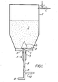
- a closed hopper 1 is partially filled with pulverised coal 2.
- Dry nitrogen at a pressure of 380 lbs/in 2 g is introduced at point B as a particle-transporting gas.
- This also pressurises the hopper through an outlet pipe 8 while normally flowing through a transport pipe 10.
- additional nitrogen which serves as a lubrication gas, is introduced at point A and enters the hopper through an inlet pipe 3 and a sintered plate 4 having 20um pores therein.
- This i partially fluidises the pulverised coal which passes through constrictions 5 in the base of a conical deflector member 6 positioned over the end 7 of an outlet pipe 8.
- the partially fluidised pulverised coal mixes with the transporting gas at the junction 9 with the transport pipe 10 which leads to the tuyeres of a slagging coal gasifier (not shown).
- the proportions of the pulverised coal may be varied by adjusting the aforementioned transport and lubrication gas flows and/or by selectively further pressurising or exhausting the hopper by means of a pressurising gas inlet C or an exhaust outlet D.
- a plurality of fluidising members 11 rest in a level position on an outer 12 and an inner 13 support ring.
- the members 11 are tack-welded to the support rings which themselves simply rest on the inner surface of the hopper wall.
- the fluidising members 11 are of sandwich construction having an upper porous plate 14 and a lower sheet metal plate 15 separated by a spacer frame 16.
- Lubrication gas is introduced into each fluidising member 11 by way of an inlet pipe 17 which is connected to the gas supply by means of an access pipe 18 and coupling flange 19.
- the fluidised particulate solids leave the storage hopper by way of an outlet pipe 20 coaxial with the inlet pipe 17.
- An access port 22, is provided in . the base of the hopper for exhausting the fuel below the members 11 for maintenance purposes.
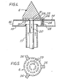
- a conical deflector member 6 and the connection of the inlet and outlet pipes 17 and 20 to the fluidising member 11 are shown in greater detail in Figures 4 and 5.
- the upper porous plate 14 is of substantially trapezoidal shape and has a central hole 23 for the outlet pipe 20 and three smaller holes (only one of which is seen) for retaining the plate 14 and the mounting flanges 26 of the conical deflector member 6 by mounting screws 25 which are screwed in threaded separator members 28 fixed to the lower plate 15.
- Constrictions 29 in the base of each deflector member 6 provide a passage to the outlet pipe 20, the end 31 of which is trimmed and welded to the sintered plate 14 in its hole 23.
- the outlet pipe 20 is mounted coaxially within the inlet pipe 17, the end 32 of which is, in turn, welded to the lower plate 15 of the fluidising member.
- the maintenance access port 22 ( Figure 2,6) comprises a tubular member 33 mounted in the bottom wall of the hopper and having a flange 34 at its lower end.
- a cover plate 35 is attached to the flange and an outlet pipe 36 is welded at 46 through a central aperture 37 in the plate 35.
- An access hole 38 normally provided with a plug 39, permits compressed gas to be introduced below a sintered plate 40 when it is desired to exhaust the hopper.
- a spacer ring 41 separates the porous plate 40 from the plate 35.
- the upper end 42 of the outlet pipe 36 is welded to the rim of an opening in the porous plate 40.
- a further flange 43 is butt welded at 45 to the _lower end of the outlet pipe 36 and this flange is normally provided with a closure plate 44.
- the hopper is constructed by inserting sections comprising the support rings 12 and 13 and welding them into complete rings.
- the upper edges of the support rings 12 and 13 are ground to provide a level support for the fluidising members 11.
- An assembly of frame 16 and lower plate 15 is mounted in position and the inlet pipes 17 then welded in place.
- the assembly 15,16 is then tack-welded to the support rings.
- the spacers 28 are positioned on the assembly using a jig 48 ( Figure 7) and tack-welded.
- the jig 48 is removed and the welds completed.
- the pulverised fuel outlet pipes 20 are placed in position, trimmed to size and welded to the sintered plate 14.
- the conical deflecting members 6 are then assembled and mounted on the sintered plates 14, which are then welded to the frames 16.
- the lubrication and pressurisation flows are cut off first.
- the particulate solids are deflected by the conical deflection members 6 and settle at the constrictions 29 where the flow can easily be restarted by again providing lubrication gas flow through the sintered plate 14.
- the outlet pipe and transport pipe are cleared by the transport gas before its flow is cut off.
- deflecting members be conical in shape provided they serve the purpose of inhibiting the direct fall of material into the outlet pipes.
- a valve may be included in the outlet pipe to isolate the transport gas flow from the hopper.
Landscapes
- Engineering & Computer Science (AREA)
- Mechanical Engineering (AREA)
- Filling Or Emptying Of Bunkers, Hoppers, And Tanks (AREA)
- Air Transport Of Granular Materials (AREA)
- Feeding, Discharge, Calcimining, Fusing, And Gas-Generation Devices (AREA)
- Devices And Processes Conducted In The Presence Of Fluids And Solid Particles (AREA)
Applications Claiming Priority (2)
| Application Number | Priority Date | Filing Date | Title |
|---|---|---|---|
| GB8039716 | 1980-12-11 | ||
| GB8039716A GB2089330B (en) | 1980-12-11 | 1980-12-11 | Discharging storage containers |
Publications (2)
| Publication Number | Publication Date |
|---|---|
| EP0054340A1 true EP0054340A1 (de) | 1982-06-23 |
| EP0054340B1 EP0054340B1 (de) | 1984-08-08 |
Family
ID=10517915
Family Applications (1)
| Application Number | Title | Priority Date | Filing Date |
|---|---|---|---|
| EP81300333A Expired EP0054340B1 (de) | 1980-12-11 | 1981-01-26 | Behälter für feinkörnige Schüttgüter |
Country Status (12)
| Country | Link |
|---|---|
| US (1) | US4560094A (de) |
| EP (1) | EP0054340B1 (de) |
| JP (1) | JPS5926565B2 (de) |
| AU (1) | AU530566B2 (de) |
| CA (1) | CA1169655A (de) |
| CS (1) | CS217993B2 (de) |
| DD (1) | DD156526A5 (de) |
| DE (1) | DE3165301D1 (de) |
| GB (1) | GB2089330B (de) |
| PL (1) | PL131092B1 (de) |
| SU (1) | SU1147245A3 (de) |
| ZA (1) | ZA81636B (de) |
Cited By (2)
| Publication number | Priority date | Publication date | Assignee | Title |
|---|---|---|---|---|
| EP2705900A1 (de) * | 2012-09-10 | 2014-03-12 | Petroval | Verfahren und Vorrichtung zum Entladen eines Partikelmaterials von einem Schiff |
| EP3037366A1 (de) * | 2014-12-22 | 2016-06-29 | The Nippon Synthetic Chemical Industry Co., Ltd. | Verfahren zum transportieren verseifter ethylenvinylesterbasierter copolymerpellets |
Families Citing this family (16)
| Publication number | Priority date | Publication date | Assignee | Title |
|---|---|---|---|---|
| US4746250A (en) * | 1983-12-13 | 1988-05-24 | Fritz Schoppe | Device for introducing a dosed quantity of powder into a carrier gas stream |
| ATE34151T1 (de) * | 1985-01-21 | 1988-05-15 | Schoppe Fritz | Vorrichtung zum dosierten eintragen eines staubes in einen traegergasstrom. |
| SE455574B (sv) * | 1985-12-27 | 1988-07-25 | Nordson Icab Ab | Anordning vid en med pulverformigt gods fyllbar behallare |
| NZ216182A (en) * | 1986-05-14 | 1989-06-28 | Nz Scientific & Ind Res | Pneumatic conveying, powder fluidising static air lock: outlet conduit between gas inlet and powder inlet |
| GB2219784B (en) * | 1988-05-27 | 1992-09-30 | Gary Kenneth Busch | Element for adapting a bulk transport container or hold of a ship to fluidise and discharge its contents and method therefor |
| US4938848A (en) * | 1989-02-13 | 1990-07-03 | Aluminum Company Of America | Method and apparatus for conveying split streams of alumina powder to an electrolysis cell |
| JPH0474263U (de) * | 1990-11-01 | 1992-06-29 | ||
| AU683669B2 (en) * | 1993-08-27 | 1997-11-20 | Geoffrey Ronald Butlin | Flow control means for a storage vessel |
| US6299387B1 (en) * | 1998-12-23 | 2001-10-09 | Rolf Andersson | Method for evacuating a storage silo for bulk goods, E.G. cereal grain, and an evacuation conveyor thereto |
| GB9913909D0 (en) * | 1999-06-16 | 1999-08-18 | Clyde Pneumatic Conveying Limi | Pneumatic conveying |
| US8087851B1 (en) | 2006-04-27 | 2012-01-03 | Jarvis R Darren | Process for handling powdered material |
| DE102008014475A1 (de) * | 2008-03-17 | 2009-11-12 | Uhde Gmbh | Verfahren und Vorrichtung zur dosierten Entnahme eines fein- bis grobkörnigen Feststoffes oder Feststoffgemisches aus einem Vorratsbehälter |
| DE102008024576B3 (de) * | 2008-05-21 | 2009-10-01 | Uhde Gmbh | Vorrichtung zum Austragen eines Feststoffes aus einem Behälter |
| US9650206B2 (en) * | 2015-07-24 | 2017-05-16 | Dynamic Aur Inc. | Conveying systems |
| DE102015216320A1 (de) * | 2015-08-26 | 2017-03-02 | Siemens Aktiengesellschaft | Pneumatisches Fördergefäß |
| NO343343B1 (en) * | 2016-11-21 | 2019-02-04 | Norsk Hydro As | Apparatus and method for feeding doses of fluidisable materials |
Citations (1)
| Publication number | Priority date | Publication date | Assignee | Title |
|---|---|---|---|---|
| US3230016A (en) * | 1962-06-01 | 1966-01-18 | Petrocarb Inc | Process and apparatus for pneumatic conveyance of solids |
Family Cites Families (15)
| Publication number | Priority date | Publication date | Assignee | Title |
|---|---|---|---|---|
| US2686617A (en) * | 1950-10-19 | 1954-08-17 | United Conveyor Corp | Method of and apparatus for discharging pulverulent material from bins |
| FR1130823A (fr) * | 1954-11-30 | 1957-02-12 | Ver Westdeutsche Waggonfab | Dispositif pour la vidange pneumatique de collecteurs contenant des matières en vrac et comportant un fond perméable à l'air |
| FR1188875A (fr) * | 1956-12-22 | 1959-09-25 | Deutsche Edelstahlwerke Ag | Dispositif d'ameublissement servant dans les réservoirs de compression destinés au transport pneumatique de matières pulvérulentes |
| DE1152058B (de) * | 1959-01-20 | 1963-07-25 | Georg Schroeder | Silo fuer pulverfoermige und fluessige Gueter, insbesondere Zement |
| DE1168829B (de) * | 1963-01-16 | 1964-04-23 | Deutsche Edelstahlwerke Ag | Plattenfoermiger Auflockerungsboden aus poroes gesintertem Material fuer Foerderrinnen, Behaelter, Silos, Bunker u. dgl. |
| US3246805A (en) * | 1964-06-29 | 1966-04-19 | Acf Ind Inc | Hopper structure |
| GB1026826A (en) * | 1964-10-29 | 1966-04-20 | Ducon Co | Conveying finely divided solids |
| US3305142A (en) * | 1965-05-21 | 1967-02-21 | Ducon Co | Aerating apparatus |
| DE1456750A1 (de) * | 1966-01-14 | 1969-03-27 | Polysius Gmbh | Vorrichtung zur pneumatischen Foerderung von Schuettgut |
| FR1559027A (de) * | 1967-12-29 | 1969-03-07 | ||
| DE1952131A1 (de) * | 1969-10-16 | 1971-04-29 | Selig Hans Joachim Dipl Ing | Fliessbettschleuse |
| CH492621A (de) * | 1969-12-11 | 1970-06-30 | Alusuisse | Entleerungsvorrichtung an Silos mit flachem Boden |
| CH503635A (de) * | 1970-08-28 | 1971-02-28 | Alusuisse | Silo mit Fördervorrichtung für staubförmiges oder feinkörniges Gut |
| LU72387A1 (de) * | 1975-04-30 | 1975-08-26 | ||
| DE2744853A1 (de) * | 1977-10-05 | 1979-04-12 | Polysius Ag | Behaelterboden zum pneumatischen austrag von feingut |
-
1980
- 1980-12-11 GB GB8039716A patent/GB2089330B/en not_active Expired
-
1981
- 1981-01-26 EP EP81300333A patent/EP0054340B1/de not_active Expired
- 1981-01-26 DE DE8181300333T patent/DE3165301D1/de not_active Expired
- 1981-01-30 CA CA000369716A patent/CA1169655A/en not_active Expired
- 1981-01-30 ZA ZA00810636A patent/ZA81636B/xx unknown
- 1981-02-11 PL PL1981229622A patent/PL131092B1/pl unknown
- 1981-02-19 AU AU67445/81A patent/AU530566B2/en not_active Ceased
- 1981-02-20 SU SU813252243A patent/SU1147245A3/ru active
- 1981-02-23 DD DD81227818A patent/DD156526A5/de not_active IP Right Cessation
- 1981-02-24 CS CS811320A patent/CS217993B2/cs unknown
- 1981-05-01 JP JP56066787A patent/JPS5926565B2/ja not_active Expired
-
1983
- 1983-07-14 US US06/513,407 patent/US4560094A/en not_active Expired - Fee Related
Patent Citations (1)
| Publication number | Priority date | Publication date | Assignee | Title |
|---|---|---|---|---|
| US3230016A (en) * | 1962-06-01 | 1966-01-18 | Petrocarb Inc | Process and apparatus for pneumatic conveyance of solids |
Cited By (4)
| Publication number | Priority date | Publication date | Assignee | Title |
|---|---|---|---|---|
| EP2705900A1 (de) * | 2012-09-10 | 2014-03-12 | Petroval | Verfahren und Vorrichtung zum Entladen eines Partikelmaterials von einem Schiff |
| KR20140034093A (ko) * | 2012-09-10 | 2014-03-19 | 뻬트로발 | 용기로부터 미립자 물질을 제거하기 위한 방법 및 장치 |
| US9446362B2 (en) | 2012-09-10 | 2016-09-20 | Petroval | Process and device for unloading particulate material from a vessel |
| EP3037366A1 (de) * | 2014-12-22 | 2016-06-29 | The Nippon Synthetic Chemical Industry Co., Ltd. | Verfahren zum transportieren verseifter ethylenvinylesterbasierter copolymerpellets |
Also Published As
| Publication number | Publication date |
|---|---|
| GB2089330B (en) | 1985-02-27 |
| AU530566B2 (en) | 1983-07-21 |
| CS217993B2 (en) | 1983-02-25 |
| GB2089330A (en) | 1982-06-23 |
| JPS5926565B2 (ja) | 1984-06-28 |
| US4560094A (en) | 1985-12-24 |
| PL131092B1 (en) | 1984-10-31 |
| AU6744581A (en) | 1982-06-17 |
| DD156526A5 (de) | 1982-09-01 |
| PL229622A1 (de) | 1982-06-21 |
| DE3165301D1 (en) | 1984-09-13 |
| JPS57102430A (en) | 1982-06-25 |
| SU1147245A3 (ru) | 1985-03-23 |
| ZA81636B (en) | 1982-03-31 |
| CA1169655A (en) | 1984-06-26 |
| EP0054340B1 (de) | 1984-08-08 |
Similar Documents
| Publication | Publication Date | Title |
|---|---|---|
| EP0054340A1 (de) | Behälter für feinkörnige Schüttgüter | |
| EP1277678B1 (de) | Vorrichtung zur Handhabung von Schüttgütern | |
| KR20100126290A (ko) | 미립 내지 조립 고체를 수용하여 컨테이너로부터 고압 시스템으로 전달하기 위한 방법 및 장치 | |
| CZ299946B6 (cs) | Zpusob a zarízení pro distribuci fluidizovatelných materiálu | |
| US3840155A (en) | Nuclear fuel handling powder container | |
| US4908124A (en) | Method and apparatus for removing foreign objects from fluid bed systems | |
| KR20100138983A (ko) | 미립자로 된 또는 먼지 형태의 고체를 컨테이너로부터 배출시키기 위한 장치 | |
| US5435442A (en) | Dry fluid substance loading device | |
| DE4225483C2 (de) | Schüttgutdrosselvorrichtung zum Entspannen, Ausschleusen, Dosieren, Dispergieren und Fördern feinkörniger Schüttgüter | |
| US4486101A (en) | Apparatus for blending particulate materials | |
| US3367724A (en) | Aerating cartridge | |
| US4242007A (en) | Method and apparatus for dispensing welding flux | |
| US4253824A (en) | Tramp removal and bed recirculation system | |
| US4289428A (en) | Particulate matter air assisted screw discharge apparatus | |
| WO1982000992A1 (en) | Conveying of bulk materials | |
| CA1185299A (en) | Pneumatic transfer system and a fluid flow control device therefor | |
| US11325776B1 (en) | Mass-flow hopper | |
| US3926788A (en) | Flux recovery unit | |
| CA1210996A (en) | Method and apparatus for removing foreign objects from fluid bed systems | |
| US4172618A (en) | Apparatus for assisting movement of a flowable material | |
| US2821439A (en) | Pneumatic powder feeder | |
| SU1328271A1 (ru) | Пневматический питатель | |
| US2877056A (en) | Method of and apparatus for feeding hot pulverulent material to a storage bin | |
| SU963577A1 (ru) | Устройство дл разделени сыпучих материалов | |
| SU1204519A1 (ru) | Камерный питатель пневмотранспортной установки |
Legal Events
| Date | Code | Title | Description |
|---|---|---|---|
| PUAI | Public reference made under article 153(3) epc to a published international application that has entered the european phase |
Free format text: ORIGINAL CODE: 0009012 |
|
| AK | Designated contracting states |
Designated state(s): BE DE FR IT NL |
|
| 17P | Request for examination filed |
Effective date: 19820608 |
|
| ITF | It: translation for a ep patent filed | ||
| GRAA | (expected) grant |
Free format text: ORIGINAL CODE: 0009210 |
|
| AK | Designated contracting states |
Designated state(s): BE DE FR IT NL |
|
| REF | Corresponds to: |
Ref document number: 3165301 Country of ref document: DE Date of ref document: 19840913 |
|
| ET | Fr: translation filed | ||
| BECH | Be: change of holder |
Free format text: 840808 *BRITISH GAS P.L.C. |
|
| PLBE | No opposition filed within time limit |
Free format text: ORIGINAL CODE: 0009261 |
|
| STAA | Information on the status of an ep patent application or granted ep patent |
Free format text: STATUS: NO OPPOSITION FILED WITHIN TIME LIMIT |
|
| 26N | No opposition filed | ||
| NLS | Nl: assignments of ep-patents |
Owner name: BRITISH GAS PLC TE LONDEN, GROOT-BRITTANNIE. |
|
| ITTA | It: last paid annual fee | ||
| REG | Reference to a national code |
Ref country code: FR Ref legal event code: TP |
|
| PGFP | Annual fee paid to national office [announced via postgrant information from national office to epo] |
Ref country code: FR Payment date: 19891212 Year of fee payment: 10 |
|
| PGFP | Annual fee paid to national office [announced via postgrant information from national office to epo] |
Ref country code: BE Payment date: 19891220 Year of fee payment: 10 |
|
| PG25 | Lapsed in a contracting state [announced via postgrant information from national office to epo] |
Ref country code: BE Effective date: 19910131 |
|
| PG25 | Lapsed in a contracting state [announced via postgrant information from national office to epo] |
Ref country code: FR Effective date: 19910930 |
|
| REG | Reference to a national code |
Ref country code: FR Ref legal event code: ST |
|
| PGFP | Annual fee paid to national office [announced via postgrant information from national office to epo] |
Ref country code: DE Payment date: 19941215 Year of fee payment: 15 |
|
| PGFP | Annual fee paid to national office [announced via postgrant information from national office to epo] |
Ref country code: NL Payment date: 19950131 Year of fee payment: 15 |
|
| PG25 | Lapsed in a contracting state [announced via postgrant information from national office to epo] |
Ref country code: NL Effective date: 19960801 |
|
| NLV4 | Nl: lapsed or anulled due to non-payment of the annual fee |
Effective date: 19960801 |
|
| PG25 | Lapsed in a contracting state [announced via postgrant information from national office to epo] |
Ref country code: DE Effective date: 19961001 |