EP0054350A1 - Leistungskondensator-Struktur und Verfahren zur Zusammensetzung - Google Patents
Leistungskondensator-Struktur und Verfahren zur Zusammensetzung Download PDFInfo
- Publication number
- EP0054350A1 EP0054350A1 EP81305177A EP81305177A EP0054350A1 EP 0054350 A1 EP0054350 A1 EP 0054350A1 EP 81305177 A EP81305177 A EP 81305177A EP 81305177 A EP81305177 A EP 81305177A EP 0054350 A1 EP0054350 A1 EP 0054350A1
- Authority
- EP
- European Patent Office
- Prior art keywords
- sections
- capacitor
- electrode
- foil
- section
- Prior art date
- Legal status (The legal status is an assumption and is not a legal conclusion. Google has not performed a legal analysis and makes no representation as to the accuracy of the status listed.)
- Granted
Links
Images

Classifications
-
- H—ELECTRICITY
- H01—ELECTRIC ELEMENTS
- H01G—CAPACITORS; CAPACITORS, RECTIFIERS, DETECTORS, SWITCHING DEVICES, LIGHT-SENSITIVE OR TEMPERATURE-SENSITIVE DEVICES OF THE ELECTROLYTIC TYPE
- H01G4/00—Fixed capacitors; Processes of their manufacture
- H01G4/32—Wound capacitors
-
- H—ELECTRICITY
- H01—ELECTRIC ELEMENTS
- H01G—CAPACITORS; CAPACITORS, RECTIFIERS, DETECTORS, SWITCHING DEVICES, LIGHT-SENSITIVE OR TEMPERATURE-SENSITIVE DEVICES OF THE ELECTROLYTIC TYPE
- H01G4/00—Fixed capacitors; Processes of their manufacture
- H01G4/38—Multiple capacitors, i.e. structural combinations of fixed capacitors
-
- Y—GENERAL TAGGING OF NEW TECHNOLOGICAL DEVELOPMENTS; GENERAL TAGGING OF CROSS-SECTIONAL TECHNOLOGIES SPANNING OVER SEVERAL SECTIONS OF THE IPC; TECHNICAL SUBJECTS COVERED BY FORMER USPC CROSS-REFERENCE ART COLLECTIONS [XRACs] AND DIGESTS
- Y10—TECHNICAL SUBJECTS COVERED BY FORMER USPC
- Y10T—TECHNICAL SUBJECTS COVERED BY FORMER US CLASSIFICATION
- Y10T29/00—Metal working
- Y10T29/43—Electric condenser making
- Y10T29/435—Solid dielectric type
Definitions
- This invention relates to electrical power capacitors, particularly for high power applications, that include a plurality of capacitor sections that are individually wound and stacked together in an enclosure with electrical interconnections therebetween and to the terminals of the enclosure.
- a capacitor unit for relatively high power applications normally comprises within a single enclosure a plurality of capacitor sections that are mutually interconnected in parallel and/or series combination to achieve the desired capacitance.
- the capacitor sections are formed individually by rolling on a mandrel sheets of dielectric material and electrode foil material. During the winding process, tabs of conductive material are inserted adjacent the foil electrodes so that merely by pressure contact with the electrodes a conductive interconnection is made between sections.
- the practice requires a certain minimum pressure or force to be applied in the wound section to establish reliable electrical contact between the conductive tabs and their adjacent foil electrodes.
- the problem is solved by winding a capacitor section in a manner so that the roll is loose enough to provide for thorough liquid impregnation and completing the section in that manner with the conductive tabs in place but without necessarily their firm adherence within the section. Then as the sections are stacked closely together within an enclosure, or can, to form a finished unit there are placed one or more pieces of sheet material between adjacent sections dimensioned to fill space and apply additional pressure intermediate the portions of the sections at which the rolled edges occur. This compacts the interior section portions in which a substantial portion of the conductive tabs are disposed.
- the stacked capacitor sections in the finished unit thus have pressure on them that at the electr6de edge portions is sufficiently light so that insulating fluid substantially completely impregnates the dielectric layers throughout the sections including the portions in the vicinity of the rolled edge and pressure intermediate the electrode edge portions is sufficiently great so the conductive tabs within the sections are in reliable pressure contact with their adjacent foil electrodes.
- the increase in pressure in the intermediate portions of the sections is not so great as to interfere with impregnation of those portions.
- the capacitor so formed has been found to be successful in retaining the advantage of the rolled edge as far as the electrical stress capability of the unit is concerned because the rolled edge can now be used with assurance of thorough impregnation, even in all film units, while at the same time insuring secure location of the conductive tabs. Yet this results from a simple to practice technique.
- the intermediate sheet material between the sections preferably extends over between about 80% and 90% of the distance between the rolled edge portions of the sections.
- the sheet material preferably comprises substantially incompressible material such as pressed hardboard or a firm plastic sheet in a thickness that is between about 5% and 10% of the rolled section thickness.
- the means employed for selectively compressing the intermediate portions of the sections can take forms other than the sheet material described above.
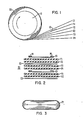
- dielectric layers Fl and F2 are on one side of electrode E1 and between it and electrode E2 while the dielectric layers F3 and F4 are on the other side of El between it and E2.
- a typical capacitor section may have about 100 turns of the six sheet materials (typically of about ten feet in length) applied around the mandrel 10.
- the winding is carried out such that the tension on the foil and film materials permits a loose enough structure so that a liquid impregnant, with which the unit 30 is filled in accordance with known practice, can fully impregnate the sections including the portions 20 in the vicinity of the rolled edges.
- a liquid impregnant with which the unit 30 is filled in accordance with known practice
- the conductive tab interconnections 34 are not loose and subject to withdrawal, there is provided between adjacent sections as they are stacked in the unit and as shown in Fig. 4 one or more pieces of sheet material 40 intermediate the rolled edge portion 20 so that the stacked sections have this additional material to force the intermediate portions 24 of the sections 22 together and to securely retain the conductive tabs 34.
- the present invention provides a simple technique for accomplishing the divergent objectives of achieving thorough impregnation in all film capacitors while retaining sufficient pressure for reliable contact with conductive tabs in capacitors in which the sections have dimensional variance due to the use of the rolled edge technique.
Landscapes
- Engineering & Computer Science (AREA)
- Power Engineering (AREA)
- Manufacturing & Machinery (AREA)
- Microelectronics & Electronic Packaging (AREA)
- Fixed Capacitors And Capacitor Manufacturing Machines (AREA)
- Resistance Welding (AREA)
- Coupling Device And Connection With Printed Circuit (AREA)
- Emergency Protection Circuit Devices (AREA)
- Amplifiers (AREA)
- Electrical Discharge Machining, Electrochemical Machining, And Combined Machining (AREA)
- Harvester Elements (AREA)
- Measuring Volume Flow (AREA)
- Vehicle Body Suspensions (AREA)
Priority Applications (1)
| Application Number | Priority Date | Filing Date | Title |
|---|---|---|---|
| AT81305177T ATE17900T1 (de) | 1980-12-12 | 1981-10-30 | Leistungskondensator-struktur und verfahren zur zusammensetzung. |
Applications Claiming Priority (2)
| Application Number | Priority Date | Filing Date | Title |
|---|---|---|---|
| US06/216,215 US4344105A (en) | 1980-12-12 | 1980-12-12 | Power capacitor structure and method of assembly |
| US216215 | 1998-12-18 |
Publications (2)
| Publication Number | Publication Date |
|---|---|
| EP0054350A1 true EP0054350A1 (de) | 1982-06-23 |
| EP0054350B1 EP0054350B1 (de) | 1986-02-05 |
Family
ID=22806214
Family Applications (1)
| Application Number | Title | Priority Date | Filing Date |
|---|---|---|---|
| EP81305177A Expired EP0054350B1 (de) | 1980-12-12 | 1981-10-30 | Leistungskondensator-Struktur und Verfahren zur Zusammensetzung |
Country Status (14)
| Country | Link |
|---|---|
| US (1) | US4344105A (de) |
| EP (1) | EP0054350B1 (de) |
| JP (1) | JPS57124415A (de) |
| AT (1) | ATE17900T1 (de) |
| AU (1) | AU546070B2 (de) |
| BR (1) | BR8107673A (de) |
| CA (1) | CA1160298A (de) |
| DE (1) | DE3173746D1 (de) |
| ES (1) | ES8304356A1 (de) |
| FI (1) | FI813950A7 (de) |
| IN (1) | IN152771B (de) |
| MX (1) | MX150347A (de) |
| NO (1) | NO153278C (de) |
| ZA (1) | ZA817118B (de) |
Cited By (1)
| Publication number | Priority date | Publication date | Assignee | Title |
|---|---|---|---|---|
| EP0072458A3 (en) * | 1981-08-18 | 1984-02-22 | Westinghouse Electric Corporation | Multi-section power capacitor with all-film dielectric |
Families Citing this family (6)
| Publication number | Priority date | Publication date | Assignee | Title |
|---|---|---|---|---|
| US4813116A (en) * | 1981-08-18 | 1989-03-21 | Westinghouse Electric Corp. | Method of making a multi-section power capacitor with all-film dielectric |
| US4480285A (en) * | 1982-12-15 | 1984-10-30 | General Electric Company | Capacitor |
| US5359487A (en) * | 1993-01-27 | 1994-10-25 | General Electric Company | Capacitor assembly of the wound-foil type |
| DE10026259A1 (de) * | 2000-05-26 | 2001-12-06 | Epcos Ag | Kondensator und Verfahren zur Herstellung des Kondensators |
| MY163624A (en) * | 2009-12-31 | 2017-10-13 | Specscan Sdn Bhd | Low inductance integrel capacitor assembly |
| DE102019217976B4 (de) * | 2019-08-26 | 2021-09-02 | Wolfgang Westermann | Folienkondensator für Leistungselektronik |
Citations (5)
| Publication number | Priority date | Publication date | Assignee | Title |
|---|---|---|---|---|
| CH134768A (de) * | 1928-08-18 | 1929-08-15 | Pfiffner Emil | Elektrischer Kondensator. |
| FR1245267A (fr) * | 1959-01-30 | 1960-11-04 | Bendix Aviat Corp | Condensateurs électriques et procédé de fabrication de ceux-ci |
| FR1581052A (de) * | 1968-07-10 | 1969-09-12 | ||
| GB2007432A (en) * | 1977-11-08 | 1979-05-16 | Fribourg Condensateurs | High Voltage Condenser |
| GB2029444A (en) * | 1978-08-31 | 1980-03-19 | Westinghouse Electric Corp | Capacitors Having Dielectric Fluid |
Family Cites Families (3)
| Publication number | Priority date | Publication date | Assignee | Title |
|---|---|---|---|---|
| US1915692A (en) * | 1928-11-01 | 1933-06-27 | Gen Electric | Condenser support |
| US1938792A (en) * | 1929-01-16 | 1933-12-12 | Gen Electric | Condenser with group clamps |
| US2773226A (en) * | 1953-08-11 | 1956-12-04 | Westinghouse Electric Corp | Capacitor |
-
1980
- 1980-12-12 US US06/216,215 patent/US4344105A/en not_active Expired - Fee Related
-
1981
- 1981-10-12 AU AU76256/81A patent/AU546070B2/en not_active Ceased
- 1981-10-14 ZA ZA817118A patent/ZA817118B/xx unknown
- 1981-10-15 IN IN1131/CAL/81A patent/IN152771B/en unknown
- 1981-10-27 MX MX189832A patent/MX150347A/es unknown
- 1981-10-28 NO NO813651A patent/NO153278C/no unknown
- 1981-10-30 AT AT81305177T patent/ATE17900T1/de not_active IP Right Cessation
- 1981-10-30 EP EP81305177A patent/EP0054350B1/de not_active Expired
- 1981-10-30 CA CA000389077A patent/CA1160298A/en not_active Expired
- 1981-10-30 DE DE8181305177T patent/DE3173746D1/de not_active Expired
- 1981-11-25 BR BR8107673A patent/BR8107673A/pt unknown
- 1981-12-09 FI FI813950A patent/FI813950A7/fi not_active Application Discontinuation
- 1981-12-11 ES ES507877A patent/ES8304356A1/es not_active Expired
- 1981-12-11 JP JP56198748A patent/JPS57124415A/ja active Pending
Patent Citations (6)
| Publication number | Priority date | Publication date | Assignee | Title |
|---|---|---|---|---|
| CH134768A (de) * | 1928-08-18 | 1929-08-15 | Pfiffner Emil | Elektrischer Kondensator. |
| FR1245267A (fr) * | 1959-01-30 | 1960-11-04 | Bendix Aviat Corp | Condensateurs électriques et procédé de fabrication de ceux-ci |
| US3085183A (en) * | 1959-01-30 | 1963-04-09 | Bendix Corp | Electrical condensers and method of making same |
| FR1581052A (de) * | 1968-07-10 | 1969-09-12 | ||
| GB2007432A (en) * | 1977-11-08 | 1979-05-16 | Fribourg Condensateurs | High Voltage Condenser |
| GB2029444A (en) * | 1978-08-31 | 1980-03-19 | Westinghouse Electric Corp | Capacitors Having Dielectric Fluid |
Cited By (1)
| Publication number | Priority date | Publication date | Assignee | Title |
|---|---|---|---|---|
| EP0072458A3 (en) * | 1981-08-18 | 1984-02-22 | Westinghouse Electric Corporation | Multi-section power capacitor with all-film dielectric |
Also Published As
| Publication number | Publication date |
|---|---|
| NO813651L (no) | 1982-06-14 |
| ATE17900T1 (de) | 1986-02-15 |
| JPS57124415A (en) | 1982-08-03 |
| NO153278B (no) | 1985-11-04 |
| AU546070B2 (en) | 1985-08-15 |
| AU7625681A (en) | 1982-06-17 |
| FI813950L (fi) | 1982-06-13 |
| NO153278C (no) | 1986-02-12 |
| US4344105A (en) | 1982-08-10 |
| ZA817118B (en) | 1983-01-26 |
| EP0054350B1 (de) | 1986-02-05 |
| DE3173746D1 (en) | 1986-03-20 |
| FI813950A7 (fi) | 1982-06-13 |
| ES507877A0 (es) | 1983-02-16 |
| MX150347A (es) | 1984-04-18 |
| ES8304356A1 (es) | 1983-02-16 |
| IN152771B (de) | 1984-03-31 |
| BR8107673A (pt) | 1982-08-24 |
| CA1160298A (en) | 1984-01-10 |
Similar Documents
| Publication | Publication Date | Title |
|---|---|---|
| US4813116A (en) | Method of making a multi-section power capacitor with all-film dielectric | |
| JP3870064B2 (ja) | ストリップを重ね合わせた巻物からなる電気エネルギーを蓄積するための装置、およびその製造方法 | |
| EP0048567B1 (de) | Veränderter Rundwickelkondensator | |
| US4344105A (en) | Power capacitor structure and method of assembly | |
| US2915808A (en) | Methods of making electrical capacitors | |
| US6740447B1 (en) | Charge storage devices with overlapping, folded electrodes | |
| EP0072458B1 (de) | Mehrfachleistungskondensator, dessen Dielektrikum wesentlich aus einem Kunststoffilm besteht | |
| US4320437A (en) | Capacitor with edge coated electrode | |
| US3093775A (en) | Series wound capacitor | |
| DE102021201343A1 (de) | Verfahren zur Herstellung einer Energiezelle sowie Energiezelle | |
| US3970904A (en) | Impregnated capacitor and method of manufacture | |
| US4945449A (en) | High voltage capacitor with high energy density | |
| DE10039436C2 (de) | Elekrochemischer Doppelschichtkondensator | |
| US3665268A (en) | Impregnated electrical capacitor | |
| JP4041926B2 (ja) | 電解コンデンサおよびその製造方法 | |
| US2104797A (en) | Electrical condenser and spacing strip therefor | |
| JP2943289B2 (ja) | アルミ電解コンデンサ | |
| JP3099772B2 (ja) | 複合フィルムコンデンサの製造方法 | |
| JPH07201646A (ja) | コンデンサの製造方法 | |
| IE56879B1 (en) | High voltage capacitor with high energy density | |
| JPS5838888B2 (ja) | 複合絶縁層を有するofケ−ブル | |
| DE3434255A1 (de) | Elektrischer wickelkondensator |
Legal Events
| Date | Code | Title | Description |
|---|---|---|---|
| PUAI | Public reference made under article 153(3) epc to a published international application that has entered the european phase |
Free format text: ORIGINAL CODE: 0009012 |
|
| AK | Designated contracting states |
Designated state(s): AT BE CH DE FR GB IT SE |
|
| 17P | Request for examination filed |
Effective date: 19821223 |
|
| ITF | It: translation for a ep patent filed | ||
| GRAA | (expected) grant |
Free format text: ORIGINAL CODE: 0009210 |
|
| AK | Designated contracting states |
Designated state(s): AT BE CH DE FR GB IT LI SE |
|
| REF | Corresponds to: |
Ref document number: 17900 Country of ref document: AT Date of ref document: 19860215 Kind code of ref document: T |
|
| ET | Fr: translation filed | ||
| REF | Corresponds to: |
Ref document number: 3173746 Country of ref document: DE Date of ref document: 19860320 |
|
| PGFP | Annual fee paid to national office [announced via postgrant information from national office to epo] |
Ref country code: AT Payment date: 19861030 Year of fee payment: 6 |
|
| PLBE | No opposition filed within time limit |
Free format text: ORIGINAL CODE: 0009261 |
|
| STAA | Information on the status of an ep patent application or granted ep patent |
Free format text: STATUS: NO OPPOSITION FILED WITHIN TIME LIMIT |
|
| 26N | No opposition filed | ||
| PG25 | Lapsed in a contracting state [announced via postgrant information from national office to epo] |
Ref country code: AT Effective date: 19871030 |
|
| PG25 | Lapsed in a contracting state [announced via postgrant information from national office to epo] |
Ref country code: SE Effective date: 19871031 Ref country code: LI Effective date: 19871031 Ref country code: CH Effective date: 19871031 Ref country code: BE Effective date: 19871031 |
|
| BERE | Be: lapsed |
Owner name: WESTINGHOUSE ELECTRIC CORP. Effective date: 19871031 |
|
| GBPC | Gb: european patent ceased through non-payment of renewal fee | ||
| PG25 | Lapsed in a contracting state [announced via postgrant information from national office to epo] |
Ref country code: FR Free format text: LAPSE BECAUSE OF NON-PAYMENT OF DUE FEES Effective date: 19880630 |
|
| REG | Reference to a national code |
Ref country code: CH Ref legal event code: PL |
|
| PG25 | Lapsed in a contracting state [announced via postgrant information from national office to epo] |
Ref country code: DE Effective date: 19880701 |
|
| REG | Reference to a national code |
Ref country code: FR Ref legal event code: ST |
|
| PG25 | Lapsed in a contracting state [announced via postgrant information from national office to epo] |
Ref country code: GB Effective date: 19881118 |
|
| EUG | Se: european patent has lapsed |
Ref document number: 81305177.8 Effective date: 19880707 |