EP0054413A1 - Caméra de télévision combinée avec ledit appareil d'enregistrement - Google Patents
Caméra de télévision combinée avec ledit appareil d'enregistrement Download PDFInfo
- Publication number
- EP0054413A1 EP0054413A1 EP81305826A EP81305826A EP0054413A1 EP 0054413 A1 EP0054413 A1 EP 0054413A1 EP 81305826 A EP81305826 A EP 81305826A EP 81305826 A EP81305826 A EP 81305826A EP 0054413 A1 EP0054413 A1 EP 0054413A1
- Authority
- EP
- European Patent Office
- Prior art keywords
- signals
- rate
- relative movement
- tape
- transducing
- Prior art date
- Legal status (The legal status is an assumption and is not a legal conclusion. Google has not performed a legal analysis and makes no representation as to the accuracy of the status listed.)
- Granted
Links
Images


Classifications
-
- H—ELECTRICITY
- H04—ELECTRIC COMMUNICATION TECHNIQUE
- H04N—PICTORIAL COMMUNICATION, e.g. TELEVISION
- H04N9/00—Details of colour television systems
- H04N9/79—Processing of colour television signals in connection with recording
-
- H—ELECTRICITY
- H04—ELECTRIC COMMUNICATION TECHNIQUE
- H04N—PICTORIAL COMMUNICATION, e.g. TELEVISION
- H04N5/00—Details of television systems
- H04N5/76—Television signal recording
- H04N5/765—Interface circuits between an apparatus for recording and another apparatus
- H04N5/77—Interface circuits between an apparatus for recording and another apparatus between a recording apparatus and a television camera
- H04N5/772—Interface circuits between an apparatus for recording and another apparatus between a recording apparatus and a television camera the recording apparatus and the television camera being placed in the same enclosure
Definitions
- This invention relates to apparatus for recording on a medium which may be elongated such as tape, and which includes a means for producing relative movement between a transducer and the medium.
- the invention also relates to such apparatus combined with a television camera.
- a recording apparatus is described in US Patent U.S. -A- 3197559, and another in US Patent U.S. -A-3962725.
- a portable television camera is customarily taken to the scene of a news event.
- the television signal generated by the camera is sent by a communications link such as a microwave link to a central point for utilization, but more commonly the signal is recorded by a portable video tape recorder (VTR) at the news scene.
- VTR portable video tape recorder
- the portable VTR used for recording the video is often in operation while being carried out. In some cases, the VTR is carried by one member of a news team while the camera is carried by another member. Furthermore, it has been proposed to combine the recorder and the television camera into a single portable unit.
- the video tape recorders used for ENG applications are amost universally of the helical-scan type in which a high tape-to-transducer relative velocity is achieved by the use of a rapidly rotating headwheel bearing the transducers, see e.g., U.S. -A- 3197559.
- a high tape-to-transducer relative velocity is achieved by the use of a rapidly rotating headwheel bearing the transducers, see e.g., U.S. -A- 3197559.
- powerful drive motors and high-gain servo loops can be used to maintain the headwheel velocity constant, but in portable equipment the power drain from the associated batteries is limited and therefore the forces which can be impressed upon the headwheel are limited.
- the motion imparted to the housing of'a portable VTR while it is being carried causes accelerations of the headwheel relative to the baseplate or housing, and thereby causes variations in the velocity of the transducers relative to the tape, which can be corrected by a particular orientation of the headwheel relative to the motion.
- This particular orientation may not be compatible with the desired overall shape of the VTR.
- a method of operating a portable video camera in conjunction with a longitudinal VTR is described in U.S. Patent, U.S. -A-3,962,725. In this arrangement, a control signal is prerecorded on the magnetic tape onto which the video signals are to be recorded.
- the prerecorded control signal is played back during the operation of recording the video and is used to control the rate of image scanning by the associated video camera.
- unavoidable changes in the speed with which the tape is driven during recording vary the rate of generation of the video signals.
- Such an arrangement requires prerecording of the magnetic tape to be used, thereby decreasing the amount of tape available for audio and video recording.
- a dropout of the prerecorded track information impairs the ability of the arrangement to produce a usable recorded tape.
- apparatus for recording signals on a recording medium comprising:
- a television recorder for recording television signals including recurrent timing signals onto an elongated medium is adapted for use in environments in which the recorder may be subject to motion. It includes a transducer by which the signals are transduced to the recording medium and also includes a rotating member coupled to the medium for causing relative motion between the medium and the transducer. The rotatable member is subject to acceleration due to motion of the recorder, whereby the timing signals may not be transduced to regularly spaced positions on the medium.
- a tachometer or speed indicating arrangement is coupled to the rotatable member for generating signals indicative of the rate of rotation of the rotatable member.
- a physically-combined camera and video tape recorder designated generally as 10 includes a body 12 connected to a handle 14.
- An optical lens arrangement 16 is coupled to an optical-to-electrical transducer illustrated as 18.
- Transducer 18 may include one or more camera tubes such as vidicons or it may include a solid-state image sensor such as a CCD array.
- a cartridge 20 for holding the magnetic tape (not shown). During operation, the magnetic tape is wound about a headwheel 22 driven by a motor 24.
- headwheel 22 may be subject to changes in velocity resulting from vertical planning of the combined camera and VTR 10. Such changes in rotational velocity change the scanning rate at which magnetic heads (not shown in FIGURE 1) associated with headwheel 22 scan, thereby affecting the distance scanned by the recording transducers across the magnetic tape per unit time. Consequently, regularly recurring vertical and horizontal sync signals included with the video are not transduced to regularly spaced positions on the tape. This in turn may lead to difficulties in reproduction upon playback.
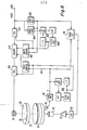
- a headwheel 22 (shown at the left of the figure) includes recording transducers 26 and 28 adapted for scanning across a magnetic tape 30 wrapped around a portion of the headwheel in known fashion and illustrated partially by phantom lines. As known, the tape 30 moves relatively slowly compared with the rotational velocity of headwheel 22 and in such a direction relative to the headwheel as to scan parallel tracks in a helical fashion upon the tape.
- Headwheel 22 is illustrated as being mechanically coupled to drive motor 24. Also coupled to headwheel 22 and motor 24 is a slip ring assembly 32 and a mechanical synchronizing signal generating wheel 34.
- Wheel 34 may for example be a transparent film upon which opaque printed patterns 320 and 330 define synchronizing signals and blanking signals, respectively.
- a lamp 36 within wheel 34 illuminates the interior and allows light to exit between the opaque portions.
- Photosensors 38 and 40 are fixedly mounted outside wheel 34 with their photosensitive surfaces directed towards lamp 36 from positions selected so that the synchronizing and blanking signals transduced thereby occur at times at which particular positions aretaken by recording transducers 26 and 28 relative to the portion of the tape 30. wrapped around the headwheel 22.
- Vertical (v) and horizontal (H) synchronizing signalc are transduced from wheel 34 by photosensor 38, and blanking signals at related times are transduced by photosensor 40.
- a phase-lock loop slaves the mechanically generated horizontal sync signals to a fixed-frequency signal.
- the phase-lock loop includes a sync signal separator 42 for separating the horizontal synchronizing signals from the composite synchronizing signals transduced by photosensor 38, and a phase detector 44 coupled to receive the separated horizontal sync signals. Also coupled to phase detector 44 are horizontal-rate signals from a divide-by-two frequency divider 46 driven by e.g., a 31.5 KHz oscillator 48.
- the output of the phase detector is applied to a low-pass filter (LPF) 50, the output of which drives a drive amplifier 52 which in turn controls the motor speed.
- LPF low-pass filter
- the loop acts to make them equal.
- the loop cannot correct instantaneously. Consequently, short periods of substantial velocity change can be expected due to mechanical motion of the recorder.
- the synchronizing or timing signals derived from wheel 34 are used to control the scanning rate of the camera portion 54 of the arrangement.
- Camera portion 54 includes a block 56 representing the vidicon 18 together with some ancillary signal processing.
- Camera portion 54 also includes the vertical and horizontal deflection circuits and windings associated with the vidicon 18 and which are schematically illustrated together as a block 76.
- the vertical and/or the horizontal deflection rates are controlled to cause the scanning rate to speed up or slow down in consonance with the appropriate mechanically derived vertical and horizontal synchronizing signals from the wheel 34.
- the ancillary processing includes gamma correction and video blanking circuits.
- Blanking signals from photosensor 40 are coupled to block 56 to operate the video blanking circuits for eliminating video during the blanking interval.
- the block 56 includes a single imaging device with a color filter for generating the video, it may also include luminance and chrominance demodulators.
- the chroma signals produced by block 56 are coupled to a chroma modulator to which is applied a 3.58 MHz (for example) subcarrier generated as described hereafter, and the modulated chrominance produced by modulator 58 is combined with luminance information in an adder 60 to produce composite luminance and chrominance information which is applied to a combiner 62.
- combiner 62 composite sync and blanking information from an adder 64 is combined with the composite chrominance and luminance information to produce composite video which is applied to slip rings 52 for coupling to recording transducers 26 and 28.
- the chroma subcarrier is locked to the mechanically generated timing signals.
- a subcarrier oscillator 66 is coupled in a phase-lock loop with a frequency divider 68 which divides by 455, a phase detector 70 and a low-pass filter 72.
- the divided subcarrier oscillator signal is compared in phase detector 70 with the H sync signal divided in a frequency divider 74 by the factor 2.
- the subcarrier oscillator is locked to e.g., 455 times half the line rate defined by the horizontal sync pulses derived from the wheel 34.
- FIGURE 3a illustrates an amplitude-time plot of a standard monochrome television signal 300 over an interval including the vertical blanking interval.
- the vertical blanking interval extends from time Tl to T5 and the active video interval extends from time T5 to the next following time Tl.
- the active video interval extends from time T5 to the next following time Tl.
- sync signals illustrated as 302.
- the horizontal-rate pulses also occur in the interval T4-T5, while double-rate pulses occur in the interval T1-T4.
- the double-rate pulses occur as serrations in a higher-level vertical synchronizing pulse.
- the imprinting 320 of a portion of transparent wheel 34 is as illustrated in developed view in FIGURE 3b.
- the opaque portions are illustrated and can be seen to correspond with those portions of the signal of 3a lying between synchronizing voltage level VS and blanking voltage level VB.
- Photosensor 38 responds to the interruption of light passing through transparent wheel 34 occasioned by the opaque pattern of FIGURE 3b to produce the sync signal.
- two transducers 26 and 28 as illustrated in FIGURE 2, one television field is transduced onto the tape for each half-rotation of the headwheel. Consequently, the sync pattern repeats twice around wheel 34.
- wheel 34 includes a 2-field sync pattern including H sync pulses for two active video intervals.
- V sync pattern for the second of the two fields differs slightly from that shown in FIGURE 3a, and consequently, the corresponding pattern for FIGURE 3b must be arranged to correspond.
- the transparent wheel 34 includes an upper imprinted portion 330, a portion of which in developed form is illustrated in FIGURE 3c. It should be noted that pattern 330 is upside down in FIGURE 3c compared with its position as illustrated in FIGURE 2.
- the raised portions of opaque pattern 330 represents those portions of the rotation of headwheel 22 at which it is expected that the signal will be blanked. As such, pattern 330 can be seen to correspond to those portions of signal 300 between blanking level VB and black level VBLK.
- a single photosensor responsive to a multitude of values can be used together with a pattern such as developed pattern 340 of FIGURE 3d. Comparison of pattern 340.with the composite sync and blanking portions of waveform 300 reveals that the opaque portion takes on different dimensions for the various components of the blanking signal. When a single transducer is used in this fashion, separation of the vertical and horizontal sync signals is required as illustrated in FIGURE 2 but adder 64 may be eliminated.
- annular magnetic strips appropriately magnetized with indicia representing the synchronizing and/or blanking signals may be used instead of wheel 34, in which case magnetic transducers would be used to transduce the mechanically produced synchronizing and blanking signals instead of photosensors 38 and 40.
- FIGURE 4 illustrates a deflection circuit 400 as described in U.S. Patent U.S.-A- 4 277 723 (Application Serial No. 094 207) filed November 19, 1979 in the name of R.L. Rodgers, III.
- a deflection winding 401 in series with a current-sensing resistor 402 is driven by an amplifier 404.
- Voltage feedback representative of the current is provided by way of a centering resistor 406 to the inverting input of amplifier 404.
- the signal applied to the noninverting input of amplifier 404 is a sawtooth generated by charging a capacitor 408 through a SIZE control resistor 410.
- a controllable switch illustrated as 414 recurrently discharges capacitor 408 in response to a synchronizing signal.
- the deflection circuit of FIGURE 4a can be used for either vertical or horizontal deflection, and the appropriate sync signal is used to discharge the capacitor.
- Regularly recurring sync pulses 420 are illustrated by solid lines in FIGURE 4b. The effect on the sync pulses when headwheel 22 is slowing down is illustrated by dotted-line pulses such as 422.
- the effect of the change in the periodic pulse rate upon the sawtooth deflection current can be understood by comparing solid- line portions 430 representing the deflection current with regularly recurring sync pulses 420 with dotted-line portions 432 representing the deflection current in response to sync pulses 422 resulting from a slowing of headwheel 22. It can be seen that the peak amplitude reached by the sawtooth waveform is greater in the case of the slowed waveform. In the case of increasing speed of headwheel 22, the sync pulses would be more.closely spaced in time and the peak amplitude of the sawtooth deflection waveform would shrink. The result of the changes in peak amplitude of the deflection waveform is change in the effective size of the image scanned by the transducer. Thus, in addition to changing the placement of sync signals on the recording medium, changes in angular velocity of the headwheel also change the apparent size of the recorded image..
- FIGURE 5 illustrates an arrangement for correcting for image size changes.
- a field-effect transistor (FET) 500 is coupled in series with size control resistor 410.
- FET 500 is operated as a resistor the magnitude of which is dependent upon source-gate voltage.
- An emitter-follower connected transistor 502 has its base connected to the source of transistor 500.
- the emitter of transistor 502 is at approximately the same voltage as the source of FET 500.
- the voltage from gate to source of transistor 500 is controlled by a pulse- counting discriminator 504 coupled to receive the appropriate vertical or horizontal synchronizing signals for producing in conjunction with a low-pass filter 506 a signal representative of the time integral of the pulses.
- This time integral signal is representative of the pulse rate and is applied across the base-emitter junction of transistor 508 and resistor 510 to produce a current representative of the pulse rate.
- the current is transduced by a PNP transistor 512 to a resistor 514 for controlling the gate-source voltage in response to the synchronizing pulse rate.
- the resistance of FET 500 changes incrementally so as to change the rate of charge of sawtooth capacitor 408 thereby maintaining a constant peak-to-peak amplitude of the deflection.
- FIGURE 6 illustrates another embodiment of the invention. Those portions of FIGURE 6 corresponding to elements of FIGURE 2 are provided with the same reference numbers.
- Video signals are provided to a terminal 600 at the right of FIGURE 6 from a source (not shown).
- a sync separator 602 coupled to terminal 600 separates horizontal synchronizing signals from the incoming video.
- a phase-lock loop including photosensor 38, sync separator 42, phase detector 44, low-pass filter 50 and drive amplifier 52 is used to control motor 24 to maintain the speed of headwheel 22 and mechanical sync producing wheel 34 at the same average rate as the separated sync from separator 602.
- the incoming video includes color subcarrier and burst.
- a burst gate 604 is gated by separated horizontal sync from separator 602 and the burst so gated is applied to a phase-lock loop (PLL) designated generally as 606 for locking an oscillator 608 to four times the subcarrier frequency (4XSC) .
- the signal from oscillator 608 is applied as a clock to an analogue to digital converter (ADC) 610 and to the write control 612 for a digital memory 614.
- ADC analogue to digital converter
- Write control 612 writes into memory 614 the digitized video from ADC 610 at the rate at which it is supplied.
- headwheel 22 may have short-term fluctuations in velocity about the average rate, reading from memory at a constant rate would result in transducing of the various timing signals including the chroma subcarrier or timing signal onto the tape at spacings which are not regular, thereby making playback difficult.
- this is corrected by coupling to the read control mechanically generated horizontal sync signals and 4XSC clock signals derived therefrom by a PLL designated generally as 616.
- a PLL designated generally as 616.
- reading from the memory is accomplished at the average rate of the incoming video, for otherwise memory 614 would overflow or become empty.
- the short-term variations in velocity of headwheel 22 are compensated for by reading from memory 614 at correspondingly increased or decreased rates.
- the signal read from memory 614 is coupled to a digital to analogue converter (D A C) 618 driven by the clock signal from PLL 616 and the resulting analog signal is applied to slip rings 32 for application to transducers 22 and 28 as in the case of FIGURE 2.
- D A C digital to analogue converter
- standard television sync signals may be generated electronically from nonstandard sync signals transduced from wheel 34.
- the effect on speed can result from other rotary members such as capstans or disc turntables, and consequently the mechanically derived sync or timing signal may be derived from capstans, idlers, turntables and the like.
- the timing signals to be regularly placed on the recording medium may as described be vertical or horizontal synchronizing signals, chroma burst or subcarrier signals or other video timing signals.
Landscapes
- Engineering & Computer Science (AREA)
- Multimedia (AREA)
- Signal Processing (AREA)
- Television Signal Processing For Recording (AREA)
- Cameras In General (AREA)
- Closed-Circuit Television Systems (AREA)
Priority Applications (1)
| Application Number | Priority Date | Filing Date | Title |
|---|---|---|---|
| AT81305826T ATE13736T1 (de) | 1980-12-15 | 1981-12-10 | Mit dem signalaufzeichnungsgeraet kombinierte fernsehkamera. |
Applications Claiming Priority (2)
| Application Number | Priority Date | Filing Date | Title |
|---|---|---|---|
| US21617080A | 1980-12-15 | 1980-12-15 | |
| US216170 | 1998-12-18 |
Publications (2)
| Publication Number | Publication Date |
|---|---|
| EP0054413A1 true EP0054413A1 (fr) | 1982-06-23 |
| EP0054413B1 EP0054413B1 (fr) | 1985-06-05 |
Family
ID=22805993
Family Applications (1)
| Application Number | Title | Priority Date | Filing Date |
|---|---|---|---|
| EP81305826A Expired EP0054413B1 (fr) | 1980-12-15 | 1981-12-10 | Caméra de télévision combinée avec ledit appareil d'enregistrement |
Country Status (4)
| Country | Link |
|---|---|
| EP (1) | EP0054413B1 (fr) |
| JP (1) | JPS57124977A (fr) |
| AT (1) | ATE13736T1 (fr) |
| DE (1) | DE3170897D1 (fr) |
Cited By (2)
| Publication number | Priority date | Publication date | Assignee | Title |
|---|---|---|---|---|
| DE3245062A1 (de) * | 1981-12-07 | 1983-06-09 | RCA Corp., 10020 New York, N.Y. | Geraet zum aufzeichnen von informationen in schraegschrift auf band |
| US4638375A (en) * | 1983-05-25 | 1987-01-20 | Sony Corporation | Video signal recording and reproducing apparatus |
Citations (5)
| Publication number | Priority date | Publication date | Assignee | Title |
|---|---|---|---|---|
| US3197559A (en) * | 1960-10-25 | 1965-07-27 | Sony Corp | Magnetic recording and reproducing system with mechanical generation of synchronizing information |
| US3470317A (en) * | 1965-01-23 | 1969-09-30 | Sony Corp | Horizontal sync pulse generation for video recording employing magnetic gear wheel |
| US3962725A (en) * | 1974-10-29 | 1976-06-08 | Eastman Kodak Company | Magnetic-tape cartridge-loaded portable video camera using prerecorded timing signals to control the video time base |
| FR2339307A1 (fr) * | 1976-01-23 | 1977-08-19 | Basf Ag | Systeme d'enregistrement et de reproduction de signaux video couleur |
| DE2701630A1 (de) * | 1977-01-17 | 1978-07-20 | Basf Ag | Aufzeichnungs-/wiedergabesystem fuer eine farbkamera |
Family Cites Families (2)
| Publication number | Priority date | Publication date | Assignee | Title |
|---|---|---|---|---|
| JPS51115806A (en) * | 1975-04-03 | 1976-10-12 | Sony Corp | Video signal recorder |
| US4277729A (en) * | 1979-11-19 | 1981-07-07 | Rca Corporation | Simplified vertical deflection circuit |
-
1981
- 1981-12-10 AT AT81305826T patent/ATE13736T1/de not_active IP Right Cessation
- 1981-12-10 EP EP81305826A patent/EP0054413B1/fr not_active Expired
- 1981-12-10 DE DE8181305826T patent/DE3170897D1/de not_active Expired
- 1981-12-14 JP JP56202384A patent/JPS57124977A/ja active Granted
Patent Citations (5)
| Publication number | Priority date | Publication date | Assignee | Title |
|---|---|---|---|---|
| US3197559A (en) * | 1960-10-25 | 1965-07-27 | Sony Corp | Magnetic recording and reproducing system with mechanical generation of synchronizing information |
| US3470317A (en) * | 1965-01-23 | 1969-09-30 | Sony Corp | Horizontal sync pulse generation for video recording employing magnetic gear wheel |
| US3962725A (en) * | 1974-10-29 | 1976-06-08 | Eastman Kodak Company | Magnetic-tape cartridge-loaded portable video camera using prerecorded timing signals to control the video time base |
| FR2339307A1 (fr) * | 1976-01-23 | 1977-08-19 | Basf Ag | Systeme d'enregistrement et de reproduction de signaux video couleur |
| DE2701630A1 (de) * | 1977-01-17 | 1978-07-20 | Basf Ag | Aufzeichnungs-/wiedergabesystem fuer eine farbkamera |
Cited By (3)
| Publication number | Priority date | Publication date | Assignee | Title |
|---|---|---|---|---|
| DE3245062A1 (de) * | 1981-12-07 | 1983-06-09 | RCA Corp., 10020 New York, N.Y. | Geraet zum aufzeichnen von informationen in schraegschrift auf band |
| DE3245062C2 (de) * | 1981-12-07 | 1995-09-07 | Rca Licensing Corp | Anordnung zur Anzeige und/oder Einstellung einer Betriebsbedingung eines Schrägspur-Bandaufzeichnungsgerätes |
| US4638375A (en) * | 1983-05-25 | 1987-01-20 | Sony Corporation | Video signal recording and reproducing apparatus |
Also Published As
| Publication number | Publication date |
|---|---|
| DE3170897D1 (en) | 1985-07-11 |
| ATE13736T1 (de) | 1985-06-15 |
| JPH0514476B2 (fr) | 1993-02-25 |
| JPS57124977A (en) | 1982-08-04 |
| EP0054413B1 (fr) | 1985-06-05 |
Similar Documents
| Publication | Publication Date | Title |
|---|---|---|
| US4321634A (en) | Endless magnetic tape video recorder/player with head centering means | |
| US4255768A (en) | Tracking control apparatus for a rotary head, variable speed signal reproducing system | |
| CA1191605A (fr) | Appareil d'enregistrement magnetique | |
| GB2083314A (en) | Video recording apparatus | |
| US4530012A (en) | Tracking control system for magnetic video recording and/or reproducing apparatus with tracking signal positions staggered with respect to the positions of tracking signals on adjacent tracks | |
| JPS6030008B2 (ja) | 再生装置 | |
| JPS627603B2 (fr) | ||
| EP0120696B1 (fr) | Appareil d'enregistrement des signaux vidéo qui sont obtenus d'une caméra avec exploration à vitesse rapide | |
| US4150395A (en) | Time base error correction system | |
| US3678186A (en) | Video tape recorder with slow motion reproducing apparatus | |
| US4402018A (en) | System using a rotating medium for recording cinematographic picture images | |
| US4594616A (en) | Recording of timing signals synchronous with a rotary recorder member | |
| US4546391A (en) | Video signal recording apparatus | |
| US4393416A (en) | Tracking system for a videotape recorder | |
| EP0227030B1 (fr) | Appareil pour l'enregistrement d'images fixes avec réduction de bruit aléatoire | |
| US3535440A (en) | High definition magnetic tape recorder for video signals | |
| EP0054413B1 (fr) | Caméra de télévision combinée avec ledit appareil d'enregistrement | |
| JPS6050105B2 (ja) | 映像信号の記録装置 | |
| US4393417A (en) | Tracking system | |
| US4734799A (en) | Apparatus for tracking magnetic head on rotary magnetic recording medium by envelope detection | |
| US4729040A (en) | Tracking apparatus for playing back rotary magnetic recording medium | |
| US3233039A (en) | Frequency modulated video film recording | |
| JPS6328392B2 (fr) | ||
| EP0708440B1 (fr) | Appareil de lecture à vitesse variable pour des signaux vidéo numériques | |
| JPS58166888A (ja) | 電子フイルム(システム)の再生装置 |
Legal Events
| Date | Code | Title | Description |
|---|---|---|---|
| PUAI | Public reference made under article 153(3) epc to a published international application that has entered the european phase |
Free format text: ORIGINAL CODE: 0009012 |
|
| AK | Designated contracting states |
Designated state(s): AT DE FR GB |
|
| 17P | Request for examination filed |
Effective date: 19821129 |
|
| GRAA | (expected) grant |
Free format text: ORIGINAL CODE: 0009210 |
|
| AK | Designated contracting states |
Designated state(s): AT DE FR GB |
|
| REF | Corresponds to: |
Ref document number: 13736 Country of ref document: AT Date of ref document: 19850615 Kind code of ref document: T |
|
| REF | Corresponds to: |
Ref document number: 3170897 Country of ref document: DE Date of ref document: 19850711 |
|
| ET | Fr: translation filed | ||
| PLBE | No opposition filed within time limit |
Free format text: ORIGINAL CODE: 0009261 |
|
| STAA | Information on the status of an ep patent application or granted ep patent |
Free format text: STATUS: NO OPPOSITION FILED WITHIN TIME LIMIT |
|
| 26N | No opposition filed | ||
| PGFP | Annual fee paid to national office [announced via postgrant information from national office to epo] |
Ref country code: GB Payment date: 19971103 Year of fee payment: 17 Ref country code: DE Payment date: 19971103 Year of fee payment: 17 Ref country code: AT Payment date: 19971103 Year of fee payment: 17 |
|
| PGFP | Annual fee paid to national office [announced via postgrant information from national office to epo] |
Ref country code: FR Payment date: 19971113 Year of fee payment: 17 |
|
| PG25 | Lapsed in a contracting state [announced via postgrant information from national office to epo] |
Ref country code: GB Free format text: LAPSE BECAUSE OF NON-PAYMENT OF DUE FEES Effective date: 19981210 Ref country code: AT Free format text: LAPSE BECAUSE OF NON-PAYMENT OF DUE FEES Effective date: 19981210 |
|
| GBPC | Gb: european patent ceased through non-payment of renewal fee |
Effective date: 19981210 |
|
| PG25 | Lapsed in a contracting state [announced via postgrant information from national office to epo] |
Ref country code: FR Free format text: LAPSE BECAUSE OF NON-PAYMENT OF DUE FEES Effective date: 19990831 |
|
| REG | Reference to a national code |
Ref country code: FR Ref legal event code: ST |
|
| PG25 | Lapsed in a contracting state [announced via postgrant information from national office to epo] |
Ref country code: DE Free format text: LAPSE BECAUSE OF NON-PAYMENT OF DUE FEES Effective date: 19991001 |