EP0054498B1 - Installation pour le dragage d'un fond sous-marin, notamment en grande profondeur - Google Patents
Installation pour le dragage d'un fond sous-marin, notamment en grande profondeur Download PDFInfo
- Publication number
- EP0054498B1 EP0054498B1 EP81402003A EP81402003A EP0054498B1 EP 0054498 B1 EP0054498 B1 EP 0054498B1 EP 81402003 A EP81402003 A EP 81402003A EP 81402003 A EP81402003 A EP 81402003A EP 0054498 B1 EP0054498 B1 EP 0054498B1
- Authority
- EP
- European Patent Office
- Prior art keywords
- working head
- arm
- dredging
- anchoring device
- plant according
- Prior art date
- Legal status (The legal status is an assumption and is not a legal conclusion. Google has not performed a legal analysis and makes no representation as to the accuracy of the status listed.)
- Expired
Links
- 238000009434 installation Methods 0.000 title description 29
- 238000004873 anchoring Methods 0.000 claims description 27
- 238000006073 displacement reaction Methods 0.000 claims description 4
- 238000004804 winding Methods 0.000 claims description 4
- 239000000463 material Substances 0.000 claims description 3
- 238000010408 sweeping Methods 0.000 claims description 3
- XLYOFNOQVPJJNP-UHFFFAOYSA-N water Substances O XLYOFNOQVPJJNP-UHFFFAOYSA-N 0.000 claims 4
- VQKWAUROYFTROF-UHFFFAOYSA-N arc-31 Chemical compound O=C1N(CCN(C)C)C2=C3C=C4OCOC4=CC3=NN=C2C2=C1C=C(OC)C(OC)=C2 VQKWAUROYFTROF-UHFFFAOYSA-N 0.000 description 1
- 230000000994 depressogenic effect Effects 0.000 description 1
- 230000014759 maintenance of location Effects 0.000 description 1
- 239000003380 propellant Substances 0.000 description 1
- 238000005096 rolling process Methods 0.000 description 1
Images
Classifications
-
- E—FIXED CONSTRUCTIONS
- E02—HYDRAULIC ENGINEERING; FOUNDATIONS; SOIL SHIFTING
- E02F—DREDGING; SOIL-SHIFTING
- E02F9/00—Component parts of dredgers or soil-shifting machines, not restricted to one of the kinds covered by groups E02F3/00 - E02F7/00
- E02F9/06—Floating substructures as supports
- E02F9/062—Advancing equipment, e.g. spuds for floating dredgers
- E02F9/065—Advancing equipment, e.g. spuds for floating dredgers characterised by the use of lines with anchors and winches
-
- E—FIXED CONSTRUCTIONS
- E02—HYDRAULIC ENGINEERING; FOUNDATIONS; SOIL SHIFTING
- E02F—DREDGING; SOIL-SHIFTING
- E02F3/00—Dredgers; Soil-shifting machines
- E02F3/04—Dredgers; Soil-shifting machines mechanically-driven
- E02F3/88—Dredgers; Soil-shifting machines mechanically-driven with arrangements acting by a sucking or forcing effect, e.g. suction dredgers
- E02F3/90—Component parts, e.g. arrangement or adaptation of pumps
- E02F3/905—Manipulating or supporting suction pipes or ladders; Mechanical supports or floaters therefor; pipe joints for suction pipes
-
- E—FIXED CONSTRUCTIONS
- E02—HYDRAULIC ENGINEERING; FOUNDATIONS; SOIL SHIFTING
- E02F—DREDGING; SOIL-SHIFTING
- E02F3/00—Dredgers; Soil-shifting machines
- E02F3/04—Dredgers; Soil-shifting machines mechanically-driven
- E02F3/88—Dredgers; Soil-shifting machines mechanically-driven with arrangements acting by a sucking or forcing effect, e.g. suction dredgers
- E02F3/90—Component parts, e.g. arrangement or adaptation of pumps
- E02F3/92—Digging elements, e.g. suction heads
- E02F3/9212—Mechanical digging means, e.g. suction wheels, i.e. wheel with a suction inlet attached behind the wheel
- E02F3/9225—Mechanical digging means, e.g. suction wheels, i.e. wheel with a suction inlet attached behind the wheel with rotating cutting elements
- E02F3/9237—Suction wheels with axis of rotation in transverse direction of the longitudinal axis of the suction pipe
Definitions
- the present invention relates to an installation for dredging an underwater bottom, for example for carrying out underwater earthworks or for extracting ores at great depths.
- One of these known installations comprises a working head, in contact with the seabed mounted on one end of a rigid arm whose other end is articulated to the hull a floating body, pivotally about a horizontal axis.
- the working head is able to carry out dredging passes on the seabed having a trajectory in the form of an arc of a circle, under the control of two butterfly cables which are anchored to the seabed in places located on either side of the working head and pass through means fixed to the working head to come and wind on two winches mounted on the floating body and actuable in the opposite direction of rotation.
- the positioning and advancement of the installation are generally carried out using two vertical anchoring piles mounted vertically mobile at the ends of the floating body. The advancement of the installation is done by pivoting the floating body around one of the two piles which is driven into the seabed, while the other pile is raised.
- the present invention aims to eliminate the aforementioned drawbacks by providing a solution which allows both dredging at great depth over a large area of the ground without the need to change the position of the floating body.
- this solution consists of a dredging installation, in particular for dredging at great depth, by which an arm carrying a working head is articulated to a support so as to pivot about a horizontal axis and two butterfly cables are provided for the control of each dredging pass movement in the form of a circular arc, which are respectively anchored to the seabed at places located on either side of the working head, outside of the sweep pass trajectory and pass by means fixed to the working head to come and wind on two winches mounted on the floating body, the latter comprising at least one device for anchoring the floating body to the seabed in a fixed working position, which is mounted on the vertically movable floating body between an anchoring position pressed into the seabed and a raised position out of this bottom, characterized in that said arm carrying the head work is mounted on a support which is vertically movable on the anchoring device, at least in the lower part thereof, between a working position in which the arm forms a relatively small angle with the anchoring device and another working position in which it
- auxiliary anchoring device vertically movable between a position pressed into the seabed and a position released from this bottom, the auxiliary device being located offset in the direction of widening of the aforementioned annular sector, of the aforementioned anchoring device, along a variable distance.
- the dredging installation comprises a floating body 1, such as a ship in the shape of a catamaran, an anchoring device for the ship, produced in the form a vertical stake 2 and a rigid arm 3 which carries at one end a working head 4 and is articulated by its other end to a support in the form of a carriage 5 mounted vertically movable along the anchoring stake 2.
- a floating body 1 such as a ship in the shape of a catamaran
- an anchoring device for the ship produced in the form a vertical stake 2 and a rigid arm 3 which carries at one end a working head 4 and is articulated by its other end to a support in the form of a carriage 5 mounted vertically movable along the anchoring stake 2.
- the arm 3 is connected to the support carriage 5 by an articulation having a horizontal axis 7.
- the carriage is provided with a set of pinions 8 driven by a motor 9 and each meshing with a rack 10 extending along the stake 2.
- the latter may be provided with laterally projecting flanges 11 behind which engage appropriate retaining members 12 associated with the carriage and which for example comprise rollers intended to come into rolling contact with the rear face of the flanges 11.
- the dredging installation comprises an auxiliary vertical pile 13 which is connected by a connecting device in the form of a parallelogram 14 to a carriage 15 mounted vertically movable along the pile 2 in the same manner as the carriage 5 In the figures, only the carriage drive motor 15 and the rack are shown at 9 'and 10'.
- This auxiliary pile 13 is further equipped with means allowing a pivoting movement in a vertical plane around the articulation connection of the parallelogram 14 to the carriage 15.
- the means for controlling the pivoting movement of the pile 13 are formed by a cable 17 fixed at one end to the pile and winding at its other end on a winch 18 mounted on the ship 1.
- the auxiliary pile 13 is situated substantially in the vertical plane in which the anchor pile 2 and the arm 3 are located with the work head 4, but, with respect to the pile 2, on the side opposite to that of the work head 4.
- the installation comprises a cable 19 which is wound on a winch 20 on board the ship 1 and is fixed at 21 to the end of the arm 3, on which the working head is mounted 4. Thanks to this cable 19, the arm 3 can pivot vertically about its horizontal pivot axis 7 of its articulation to the support carriage 5.
- the device ensuring the pivoting of the arm 3 around the vertical axis comprises two butterfly cables 22 anchored at 23 to the seabed 16 on either side of the arm 3. Each cable22 passes over a pulley 24 fixed to the lower or free end of the arm 3 and is wound on a winch 25 mounted on the vessel 1, passing over another deflection pulley 26 provided in the upper part of arm 3.
- the anchor pile 2 is mounted at 34 on the ship 1, vertically sliding between an anchor position in which its lower end is pressed into the seabed (FIG. 1) and a raised underwater bottom release position (Figure 3).
- the auxiliary pile 13 is also likely to be driven into the seabed or to assume a raised position.
- the working head 4 can be produced in the form of a suction head whether or not equipped with a cutting tool such as a shovel wheel 27 which can be held in position by a jack 28.
- a suction pump 29 mounted inside the arm 3 and which delivers the materials sucked through a transfer pipe 30 of these materials to a storage location, not shown.
- the motors 9 and 9 'intended for the movement of the carriages 5 and 15 and the suction and discharge pump 29 as well as the actuator 28 can be remote-controlled, for example from the vessel 1, in any case appropriate and known.
- the shovel wheel 27 of the working head 4 can be advanced to line 32 representing the trajectory of the next dredging pass, without it being necessary to move the vessel 1
- the working head 4 can thus sweep by successive parallel passes an annular sector 33 (FIG. 2).
- the limit of scanning by successive parallel passes without changing the position of the vessel 1 is reached when the carriage 5 is in the position shown in phantom lines in FIG. 1, in which the arm 3 extends horizontally.
- the exact position of the shovel wheel 27 can be adjusted by means of its jack 28.
- the upward movement of the carriage 5 causes the desired advancement of the ship 1.
- the throttle cables 22 are kept taut to prevent the working head 4 from skids on the bottom and moves backwards. Since the auxiliary pile 13 remains in its depressed position in the bottom 16 during the whole operation of advancing the ship 1, the latter is always anchored to the seabed and the advancement operation is perfectly controllable.
- the dredging installation according to the invention makes it possible to work on the seabed at depths up to 100 meters and even more and scanning by successive parallel passes without changing the working position of the installation, and this in particular thanks to the articulation of the carrier arm of the working head to a motor carriage movable along the anchoring stake 2 to the seabed 16.
- the embodiment which has just been described and which is shown in the figures has been given only by way of example. Of course, many variants can be made to this embodiment.
- the configuration and mounting of the two carriages on the main anchor pile 2 can be different and of any suitable nature known to those skilled in the art.
- the working head is also not limited to the structure described and shown.
- the ship can be equipped with an autonomous or additional propellant device to facilitate the advancement maneuver.
- the anchoring stake can be produced in any suitable form and have a cross section of any suitable form.
- the extreme part of the pile which is intended to be inserted into the seabed, is advantageously made in the form of a separate body mounted to rotate and, if necessary, vertically movable in the pile.
- the pile can be made up of a multitude of assemblable sections so that it is adaptable to the depth of the seabed.
Landscapes
- Engineering & Computer Science (AREA)
- Mining & Mineral Resources (AREA)
- Civil Engineering (AREA)
- General Engineering & Computer Science (AREA)
- Structural Engineering (AREA)
- Mechanical Engineering (AREA)
- Placing Or Removing Of Piles Or Sheet Piles, Or Accessories Thereof (AREA)
- Earth Drilling (AREA)
Description
- La présente invention concerne une installation de dragage d'un fond sous-marin, par exemple pour la réalisation des terrassements sous-marins ou pour l'extraction des minerais à grande profondeur.
- On connait déjà diverses installations de dragage, notamment pour le dragage en grande profondeur, en particulier par aspiration.
- L'une des ces installations connues, mentionnée dans le brevet américain n° 4212 121 comporte une tête de travail, en contact avec le fond sous-marin montée sur une extrémité d'un bras rigide dont l'autre extrémité est articulée à la coque d'un corps flottant, de façon pivotante autour d'un axe horizontal. La tête de travail est en mesure d'effectuer sur le fond sous-marin des passes de dragage ayant une trajectoire en forme d'un arc de cercle, sous la commande de deux câbles de papillonnage qui sont ancrés au fond marin à des endroits situés de part et d'autre de la tête de travail et passent par des moyens fixés à la tête de travail pour venir s'enrouler sur deux treuils montés sur le corps flottant et actionnable en sens de rotation inverse. Le positionnement et l'avancement de l'installation s'effectuent en général à l'aide de deux pieux d'ancrage verticaux montés verticalement mobiles aux extrémités du corps flottant. L'avancement de l'installation se fait par pivotement du corps flottant autour de l'un des deux pieux qui est enfoncé dans le fond sous-marin, tandis que l'autre pieux est soulevé.
- Cependant, une telle installation présente des inconvénients considérables. Etant donné que le bras porteur de la tête de travail est articulé directement à la coque du corps flottant, cette installation ne permet pas un dragage en grande profondeur et son utilisation est pratiquement limitée à des profondeurs de l'ordre de vingt mètres. Du fait de l'articulation du bras à un endroit fixe du corps flottant, la tête de travail ne peut effecteur qu'une seule passe de dragage pour une position fixe de l'installation. Il est évident que l'obligation d'avancer l'installation à l'aide de deux pieux, après chaque passe de dragage, constitue une contrainte extrêmement gênante.
- Une autre installation de dragage connue, est mentionnée dans la demande de brevet français n° 2 383 273 qui révèle une installation de dragage comprenant un bras porteur d'une tête de travail qui est montée sur un support déplaçable verticalement sur le dispositif d'ancrage. Le mouvement latéral de la tête de travail est commandé par des moyens faisant partie du chariot auquel le support est relié. D'autre part, le bras a plusieurs positions de travail.
- Cependant, le déplacement vertical du chariot auquel est relié le support de la tête de travail ne sert exclusivement que pour amener le support dans la zone de travail à proximité du sol. Il en résulte l'inconvénient majeur qu'une telle installation ne peut travailler une zone importante du sol sans qu'il soit nécessaire de changer la position du corps flottant.
- La présente invention a pour but d'éliminer les inconvénients précités en fournissant une solution qui permet à la fois un dragage en grande profondeur sur une zone importante du sol sans qu'il soit nécessaire de changer la position du corps flottant.
- Cette solution consiste, selon la présente invention, en une installation de dragage, notamment pour le dragage en grande profondeur, par laquelle un bras porteur d'une tête de travail est articulé à un support de façon pivotante autour d'un axe horizontal et deux câbles de papillonnage sont prévus pour la commande de chaque mouvement de passe de dragage en forme d'un arc de cercle, qui sont respectivement ancrés au fond marin à des endroits situés de part et d'autre de la tête de travail, en dehors de la trajectoire de passe de balayage et passent par des moyens fixés à la tête de travail pour venir s'enrouler sur deux treuils montés sur le corps flottant, ce dernier comportant au moins un dispositif d'ancrage du corps flottant au fond sous-marin dans une position fixe de travail, qui est monté sur le corps flottant verticalement mobile entre une position d'ancrage enfoncée dans le fond marin et une position soulevée hors de ce fond, caractérisé en ce que ledit bras porteur de la tête de travail est monté sur un support qui est verticalement déplaçable sur le dispositif d'ancrage, au moins dans la partie inférieure de celui-ci, entre une position de travail dans laquelle le bras forme un angle relativement faible avec le dispositif d'ancrage et une autre position de travail dans laquelle il est sensiblement parallèle au fond, le déplacement vertical du support entre les deux positions de travail entraînant un mouvement de la tête de travail sur le fond marin, en avant ou en arrière, selon la direction du déplacement du support.
- Suivant une caractéristique avantageuse de l'installation selon l'invention, celle-ci comprend un dispositif d'ancrage auxiliaire verticalement mobile entre une position enfoncée dans le fond sous-marin et une position dégagée de ce fond, le dispositif auxiliaire étant situé décalé dans la direction d'élargissement du secteur annulaire précité, du dispositif d'ancrage précité, suivant une distance variable.
- L'invention sera mieux comprise et d'autres buts, caractéristiques, détails et avantages de celle-ci apparaîtront plus clairement au cours de la description explicative qui va suivre faite en référence aux dessins schématiques annexés donnés uniquement à titre d'exemple illustrant un mode de réalisation de l'invention et dans lesquels:
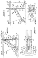
- La figure 1 est une vue en élévation de l'installation de dragage selon l'invention, dans sa position de travail.
- La figure 2 est une vue de dessus avec arrachement partiel, de l'installation de dragage suivant la figure 1.
- La figure 3 montre l'installation suivant l'invention pendant son avancement vers une nouvelle position de travail, en une vue en élévation; et La figure 4 est une vue en coupe schématique et à plus grande échelle, suivant la direction IV-IV de la figure 3.
- Suivant le mode de réalisation de l'invention, représenté sur les figures, l'installation de dragage comprend un corps flottant 1, tel qu'un navire en forme d'un catamaran, un dispositif d'ancrage pour le navire, réalisé sous forme d'un pieu vertical 2 et un bras rigide 3 qui porte à une extrémité une tête de travail 4 et est articulé par son autre extrémité à un support en forme d'un chariot 5 monté verticalement mobile le long du pieu d'ancrage 2.
- Comme il est illustré à la figure 4 de façon schématique, le bras 3 est relié au chariot de support 5 par une articulation présentant un axe horizontal 7.
- Pour assurer son déplacement le long du pieu d'ancrage 2, le chariot est pourvu d'un jeu de pignons 8 entraîné par un moteur 9 et engrènant chacun une crémaillère 10 s'étendant le long du pieu 2. Pour assurer la retenue du chariot sur le pieu, ce dernier peut être pourvu de rebords latéralement saillants 11 derrière lesquels viennent en prise des organes de retenue appropriés 12 associés au chariot et qui comprennent par exemple des galets destinés à venir en contact roulant avec la face arrière des rebords 11.
- L'installation de dragage selon l'invention comprend un pieu vertical auxiliaire 13 qui est relié par un dispositif de liaison en forme d'un parallèlogramme 14 à un chariot 15 monté verticalement mobile le long du pieu 2 de la même manière que le chariot 5. Sur les figures seuls le moteur d'entraînement du chariot 15 et la crémaillère sont représentés en 9' et 10'. Ce pieu auxiliaire 13 est en outre équipé de moyens permettant un mouvement de pivotement dans un plan vertical autour de la liaison par articulation du parallèlogramme 14 au chariot 15. Bien entendu la liaison entre le parallèlogramme 14 et le pieu auxiliaire 13 permet également un mouvement de pivotement relatif de ces deux pièces. Les moyens de commande du mouvement de pivotement du pieu 13 sont formés par un câble 17 fixé à une extrémité au pieu et s'enroulant à son autre extrémité sur un treuil 18 monté sur le navire 1. Il est encore à noter que le pieu auxiliaire 13 est situé sensiblement dans le plan vertical dans lequel se trouvent le pieu d'ancrage 2 et le bras 3 avec la tête de travail 4, mais, par rapport au pieu 2, du côté opposé à celui de la tête de travail 4.
- Pour la commande de la tête de travail 4, l'installation comprend un câble 19 qui est enroulé sur un treuil 20 à bord du navire 1 et est fixé en 21 à l'extrémité du bras 3, sur laquelle est montée la tête de travail 4. Grâce à ce câble 19, le bras 3 peut pivoter verticalement autour de son axe de pivotement horizontal 7 de son articulation au chariot de support 5. Le dispositif assurant le pivotement du bras 3 autour de l'axe vertical comprend deux câbles de papillonnage 22 ancrés en 23 au fond sous-marin 16 de part et d'autre du bras 3. Chaque câble22 passe sur une poulie 24 fixée à l'extrémité inférieure ou libre du bras 3 et vient s'enrouler sur un treuil 25 monté sur le navire 1, en passant sur une autre poulie de renvoi 26 prévue dans la partie supérieure du bras 3.
- Comme il ressort notamment des figures 1 et 3, le pieu d'ancrage 2 est monté en 34 sur le navire 1, verticalement coulissant entre une position d'ancrage dans laquelle son extrémité inférieure est enfoncée dans le fond marin (figure 1) et une position soulevée de dégagement du fond sous-marin (figure 3). Le pieu auxiliaire 13 est également susceptible d'être enfoncé dans le fond marin ou de prendre une position soulevée.
- Il est encore à noter que la tête de travail 4 peut être réalisée sous forme d'une tête d'aspiration équipée ou non d'un outil de coupe tel qu'une roue-pelle 27 pouvant être maintenue en position par un vérin 28. A la tête d'aspiration est associée une pompe aspirante 29 montée à l'intérieur du bras 3 et qui refoule les matériaux aspirés à travers une conduite de transfert 30 de ces matériaux vers un lieu de stockage non représenté.
- Il convient encore de souligner que les moteurs 9 et 9' destinés au déplacement des chariots 5 et 15 et la pompe d'aspiration et de refoulement 29 ainsi que le vérin 28 peuvent être télécommandés, par exemple à partir du navire 1, de toute manière appropriée et connue.
- L'installation de dragage selon l'invention fonctionne de la façon suivante:
- La figure 1 montre l'installation dans une position fixe de travail. La pointe du pieu d'ancrage 2 est enfoncée dans le fond sous-marin 16. Le chariot 5 auquel est articulé le bras 3 porteur de la tête en travail 4 se trouve dans sa position haute. Le chariot est maintenu dans cette position pendant toute la durée d'une passe de dragage effectuée par la tête de travail 4. La trajectoire de cette passe de dragage est en forme d'un arc de cercle représenté en 31 sur la figure 2. Ce mouvement de balayage de la tête 4 suivant l'arc de cercle 31 est commandé à l'aide des deux treuils 25 et des deux câbles de papillonnage 22. Suivant la direction désirée du mouvement de balayage au cours de la passe de dragage, on enroule l'un des deux câbles 22 sur un treuil 25 et relâche l'autre câble en faisant tourner son treuil dans le sens de rotation inverse, de façon synchrone avec la rotation du treuil 25 fonctionnant dans le sens d'un enroulement de son câble.
- Après accomplissement de la passe de dragage 31, la roue-pelle 27 de la tête de travail 4 peut être avancée jusqu'à la ligne 32 représentant la trajectoire de la passe de dragage suivante, sans qu'il soit nécessaire de déplacer le navire 1. Il suffit pour cela de déplacer vers le bas le chariot 5 auquel est articulé le bras 3 porteur de la tête de travail 4, suivant une distance appropriée. En effet, tout déplacement vertical du chariot 5 entraîne un mouvement de la roue-pelle 27 sur le fond marin, en avant ou en arrière selon la direction du déplacement du chariot 5, étant donné que le pieu d'ancrage 2 est maintenu fixe et la roue-pelle 27 est en contact avec le fond marin 16. L'opération d'avancement de la roue 27 terminée, ou immobilise le chariot 5 et amène la tête de travail 4 à effectuer la passe de dragage suivant l'arc de cercle 32 à l'aide des treuils 25 et des câbles 22. On comprend aisément que la tête de travail 4 peut ainsi balayer par passes parallèles successives un secteur annulaire 33 (figure 2). La limite du balayage par passes parallèles successives sans changement de position du navire 1 est atteint lorsque le chariot 5 se trouve dans la position représentée en lignes fantômes sur la figure 1, dans laquelle le bras 3 s'étend horizontalement. La position exacte de la roue-pelle 27 peut être réglée au moyen de son vérin 28.
- Ce n'est qu'après le balayage du secteur annulaire 33 (figure 2) que le navire doit être avancé vers sa prochaine position fixe de travail. La tête de travail 4, avec sa roue-pelle 27, reste posée sur le fond 16 et constitue un point fixe, en raison de son poids. Le pieu auxiliaire 13 est descendu par déplacement de son chariot de support 15 vers le bas, le long du pieu d'ancrage 2, et fiché dans le fond sous-marin 16. Ensuite, le pieu d'ancrage 2 est soulevé hors du fond 16. Puis on remonte le chariot 5 auquel est articulé le bras 3 porteur de la tête de travail 4, grâce au moteur 9 du chariot par exemple jusqu'à ce que l'angle a est formé entre les axes du pieu 2 et du bras 3 atteigne une valeur d'environ 45°. Du fait de immobilité de la lourde tête de travail 4 sur le fond marin 16, le mouvement ascendant du chariot 5 provoque l'avancement voulu du navire 1. Simultanément les câbles de papillonage 22 sont maintenus tendus pour éviter que la tête de travail 4 ne dérape sur le fond et se déplace vers l'arrière. Etant donné que le pieu auxiliaire 13 reste dans sa position enfoncée dans le fond 16 pendant toute l'opération d'avancement du navire 1, ce dernier est toujours ancré au fond sous-marin et l'opération d'avancement est parfaitement contrôlable.
- Lorsque le navire est arrivé dans sa nouvelle position fixe de travail, le pieu d'ancrage 2 est à nouveau fiché dans le fond et le pieu auxiliaire 13 soulevé à l'aide de son câble 17 et du treuil 18. Puis on remonte le chariot 15 le long du pieu 2 jusqu'à ce que le pieu auxiliaire 13 revienne dans sa position représentée sur la figure 1. L'opération d'avancement est ainsi terminée, et une nouvelle opération de dragage peut commencer.
- On comprend aisément que l'installation de dragage selon l'invention permet de travailler sur le fond marin à des profondeurs jusqu'à 100 mètres et même plus et le balayage par passes parallèles successives sans changement de la position de travail de l'installation, et ceci notamment grâce à l'articulation du bras-porteur de la tête de travail à un chariot moteur déplaçable le long du pieu d'ancrage 2 jusqu'au fond sous-marin 16.
- Le mode de réalisation qui vient d'être décrit et qui est représenté sur-les figures n'a été donné qu'à titre d'exemple. Bien entendu de nombreuses variantes peuvent être apportées à ce mode de réalisation. La configuration et le montage des deux chariots sur le pieu d'ancrage principal 2 peuvent être différents et de toute nature appropriée connue à l'homme du métier. La tête de travail n'est également pas limitée à la structure décrite et représentée. Le navire peut être équipé d'un dispositif propulseur autonome ou supplémentaire pour faciliter la manoeuvre de l'avancement. Il est encore à noter que le pieu d'ancrage peut être réalisé sous toutes formes appropriées et avoir une section transversale de toute forme appropriée.
- La partie extrême du pieu, qui est destinée à être fichée dans le fond sous-marin est avantageusement réalisée sous forme d'un corps séparé monté rotatif et, le cas échéant, verticalement déplaçable dans le pieu.
- Le pieu peut être composé d'une multitude de sections assemblables pour qu'il soit adaptable à la profondeur du fond sous-marin.
Claims (9)
Applications Claiming Priority (2)
| Application Number | Priority Date | Filing Date | Title |
|---|---|---|---|
| FR8026683A FR2500868A1 (fr) | 1980-12-16 | 1980-12-16 | Procede de dragage d'un fond sous-marin, notamment en grande profondeur, et installation pour la mise en oeuvre de ce procede |
| FR8026683 | 1980-12-16 |
Publications (2)
| Publication Number | Publication Date |
|---|---|
| EP0054498A1 EP0054498A1 (fr) | 1982-06-23 |
| EP0054498B1 true EP0054498B1 (fr) | 1985-05-29 |
Family
ID=9249151
Family Applications (1)
| Application Number | Title | Priority Date | Filing Date |
|---|---|---|---|
| EP81402003A Expired EP0054498B1 (fr) | 1980-12-16 | 1981-12-15 | Installation pour le dragage d'un fond sous-marin, notamment en grande profondeur |
Country Status (5)
| Country | Link |
|---|---|
| US (2) | US4445290A (fr) |
| EP (1) | EP0054498B1 (fr) |
| CA (2) | CA1167074A (fr) |
| DE (1) | DE3170778D1 (fr) |
| FR (1) | FR2500868A1 (fr) |
Families Citing this family (15)
| Publication number | Priority date | Publication date | Assignee | Title |
|---|---|---|---|---|
| FR2536439B1 (fr) * | 1982-11-19 | 1985-08-09 | Valeo | Drague a stabilite amelioree |
| US4485569A (en) * | 1983-05-06 | 1984-12-04 | Mitsubishi Jukogyo Kabushiki Kaisha | Spud arrangement for a dredge |
| US5791074A (en) * | 1993-07-15 | 1998-08-11 | Minpro Australia N.L. | Dredge |
| AU674599B2 (en) * | 1993-07-15 | 1997-01-02 | Minpro Australia N.L. | Dredge |
| US5421109A (en) * | 1994-01-31 | 1995-06-06 | American Oilfield Divers, Inc. | Underwater site clearance sweep apparatus and method |
| GB2315787B (en) * | 1996-03-01 | 1999-07-21 | Seabed Impeller Levelling And | Dredging apparatus |
| EP0826836A1 (fr) * | 1996-09-03 | 1998-03-04 | Ballast Nedam Grond en Wegen B.V. | Embarcation comportant une élinde verticale avec outils pour travaux sous l'eau |
| US20050194367A1 (en) * | 2004-03-02 | 2005-09-08 | Fredrick William G.Jr. | System and method for remote controlled actuation of laser processing head |
| US20060123671A1 (en) * | 2004-12-14 | 2006-06-15 | Cornelis Heuvelman | Cutter suction dredge |
| SG187841A1 (en) * | 2010-08-13 | 2013-03-28 | Deep Reach Technology Inc | Subsea excavation systems and methods |
| NL2007694C2 (en) * | 2011-11-01 | 2013-05-07 | Ihc Holland Ie Bv | Anchoring system. |
| US10287746B1 (en) | 2015-12-14 | 2019-05-14 | Dsc Dredge, Llc | Wide-format swinging ladder dredge |
| US10526050B1 (en) | 2018-09-18 | 2020-01-07 | Johnson Outdoors Inc. | Shallow water anchor with hydraulic actuation |
| GB2622764A (en) * | 2022-06-15 | 2024-04-03 | Atureliya Senake | Subterranean space creation and utilisation solutions |
| CN118081368B (zh) * | 2024-04-23 | 2024-06-25 | 江苏惠泽润尔能源科技有限公司 | 一种疏水阀组装机 |
Family Cites Families (26)
| Publication number | Priority date | Publication date | Assignee | Title |
|---|---|---|---|---|
| US1019610A (en) * | 1912-01-25 | 1912-03-05 | William Thomas Donnelly | Dredging apparatus. |
| US1792065A (en) * | 1927-05-13 | 1931-02-10 | George F Hogan | Dredge |
| US1962363A (en) * | 1933-10-02 | 1934-06-12 | Paul D Reimel | Bucket dredge |
| US2308743A (en) * | 1939-09-16 | 1943-01-19 | William P Bulkley | Barge |
| US2271344A (en) * | 1940-12-23 | 1942-01-27 | John D Rauch | Reclinable spud construction |
| DE963574C (de) * | 1954-07-15 | 1957-05-09 | Orenstein & Koppel Ag | Einrichtung fuer Verholleinen |
| US3206875A (en) * | 1962-07-12 | 1965-09-21 | American Marine & Machinery Co | Hydraulic drive means for dredge comprising means for the selective injection or withdrawal of pressure fluid from a motor driving circuit |
| GB974458A (fr) * | 1962-10-17 | |||
| US3218739A (en) * | 1963-05-13 | 1965-11-23 | Ellicott Machine Corp | Dredge |
| NL301281A (fr) * | 1963-12-03 | |||
| US3495409A (en) * | 1967-01-10 | 1970-02-17 | Wilhelm Riedemann | Apparatus for building a retaining wall along a bank of a body of water |
| NL129899C (fr) * | 1968-03-12 | |||
| US3591936A (en) * | 1969-01-15 | 1971-07-13 | Koninkl Mij Tot Het Uitvoeren | Submarine cutter dredger |
| DE2051941A1 (de) * | 1969-11-05 | 1971-05-13 | Dan Ionescu Sisesti, Bukarest | Schwimmsaugbagger mit beweglichem Saugrohr |
| US3656449A (en) * | 1970-06-01 | 1972-04-18 | Herbert W Mead | Propelling means for a dredge |
| FR2102603A5 (fr) * | 1970-08-11 | 1972-04-07 | Dragages Tp Fse Entr | |
| US3755932A (en) * | 1971-06-23 | 1973-09-04 | N Cargile | Jack-up dredge |
| BE789136A (fr) * | 1971-09-23 | 1973-03-22 | Duval Leonard A | Appareil pour draguer des solides divises submerges dans un liquide |
| GB1460807A (en) * | 1974-04-08 | 1977-01-06 | Hattum & Blankevoort Bv | Dredge |
| US3983707A (en) * | 1975-03-05 | 1976-10-05 | Georgy Mikhailovich Lezgintsev | Method and apparatus for moving an object on the bottom of a body of water |
| NL182741C (nl) * | 1975-09-05 | 1988-05-02 | Ihc Holland Nv | Zuigbaggerinrichting met vaartuig, ladder, zuigbuis, snijorgaan of graafwiel. |
| US4073078A (en) * | 1975-11-03 | 1978-02-14 | Leitz Julius H | Adjustable dredging and trenching apparatus |
| NL165808C (nl) * | 1977-03-08 | 1981-05-15 | Ballast Nedam Groep Nv | Zuigbaggerinstallatie. |
| FR2395361A1 (fr) * | 1977-06-23 | 1979-01-19 | Ferodo Sa | Drague |
| US4212121A (en) * | 1978-07-31 | 1980-07-15 | Mitsubishi Jukogyo Kabushiki Kaisha | Method and apparatus for dredging having bow-stern movement of the suction means |
| FR2453945A1 (fr) * | 1979-04-10 | 1980-11-07 | Bibaut Gilbert | Engin pour le curage des etangs, marais ou canaux |
-
1980
- 1980-12-16 FR FR8026683A patent/FR2500868A1/fr active Granted
-
1981
- 1981-12-14 US US06/330,788 patent/US4445290A/en not_active Ceased
- 1981-12-15 DE DE8181402003T patent/DE3170778D1/de not_active Expired
- 1981-12-15 EP EP81402003A patent/EP0054498B1/fr not_active Expired
- 1981-12-16 CA CA000392454A patent/CA1167074A/fr not_active Expired
-
1985
- 1985-06-28 US US06/749,638 patent/USRE32297E/en not_active Expired - Fee Related
- 1985-11-07 CA CA000494858A patent/CA1224815B/fr not_active Expired
Also Published As
| Publication number | Publication date |
|---|---|
| USRE32297E (en) | 1986-12-02 |
| US4445290A (en) | 1984-05-01 |
| DE3170778D1 (en) | 1985-07-04 |
| FR2500868A1 (fr) | 1982-09-03 |
| EP0054498A1 (fr) | 1982-06-23 |
| FR2500868B1 (fr) | 1984-12-28 |
| CA1167074A (fr) | 1984-05-08 |
| CA1224815B (fr) | 1987-07-28 |
Similar Documents
| Publication | Publication Date | Title |
|---|---|---|
| EP0054498A1 (fr) | Installation pour le dragage d'un fond sous-marin, notamment en grande profondeur | |
| EP3902742B1 (fr) | Dispositif d'accueil pour un vehicule sous-marin | |
| WO2008012472A1 (fr) | Appareil de recuperation d'un engin sous-marin ou marin | |
| FR3091258A1 (fr) | Dispositif d’accueil pour un véhicule sous-marin | |
| EP0876748A1 (fr) | Appareil ou machine comportant une unité de travail articulée par rapport à une structure porteuse et procédé d'articulation | |
| FR2580267A1 (fr) | Dispositif de manoeuvre de cables ou conduites tubulaires flexibles passant sur un organe deviateur | |
| FR2740427A1 (fr) | Navire tracte par cerf-volant via un bras articule | |
| EP0225243B1 (fr) | Machine pour creuser des tranchées dans le sol | |
| FR2475681A1 (fr) | Dispositif d'ensouillage de cables ou conduites tubulaires flexibles dans le fond sous-marin | |
| EP0592326B1 (fr) | Appareil pour creuser dans le sol des tranchées de grande profondeur à l'aide de tambours de fraisage | |
| FR2533110A1 (fr) | Machine mobile d'eclaircissage de forets | |
| EP0093637A1 (fr) | Installation de mise en tas et de reprise de matériaux en vrac | |
| EP0139596A2 (fr) | Dispositif pour effectuer un travail sur une structure sous-marine à plusieurs branches | |
| CA1092551A (fr) | Systeme d'excavation en mer a guidage horizontal de la benne preneuse au moyen de cables | |
| FR2815476A1 (fr) | Dispositif de deplacement d'un mat mobile destine au support d'au moins une antenne | |
| FR2539157A1 (fr) | Trancheuse a fleche | |
| FR2544062A1 (fr) | Dispositif de transport d'un canon ou analogue | |
| FR3115524A1 (fr) | Plateforme nautique de nettoyage de crassats | |
| EP1546471B1 (fr) | Outil d excavation pour pelleteuse hydraulique | |
| WO2023180649A1 (fr) | Dispositif de fixation pour la fixation d'un moteur hors-bord a une embarcation | |
| FR3133831A1 (fr) | dispositif de fixation pour la fixation d’un moteur hors-bord à une embarcation | |
| CH631409A5 (fr) | Dispositif raclant, notamment pour les centrales a beton. | |
| EP3012219A1 (fr) | Dispositif de terrassement adaptable sur le tablier d'un chariot telescopique | |
| CA1273965A (fr) | Procede et dispositif de creusement de puits | |
| EP0750702B1 (fr) | Tractopelle |
Legal Events
| Date | Code | Title | Description |
|---|---|---|---|
| PUAI | Public reference made under article 153(3) epc to a published international application that has entered the european phase |
Free format text: ORIGINAL CODE: 0009012 |
|
| AK | Designated contracting states |
Designated state(s): BE DE GB NL |
|
| 17P | Request for examination filed |
Effective date: 19821216 |
|
| GRAA | (expected) grant |
Free format text: ORIGINAL CODE: 0009210 |
|
| AK | Designated contracting states |
Designated state(s): BE DE GB NL |
|
| REF | Corresponds to: |
Ref document number: 3170778 Country of ref document: DE Date of ref document: 19850704 |
|
| PLBE | No opposition filed within time limit |
Free format text: ORIGINAL CODE: 0009261 |
|
| STAA | Information on the status of an ep patent application or granted ep patent |
Free format text: STATUS: NO OPPOSITION FILED WITHIN TIME LIMIT |
|
| 26N | No opposition filed | ||
| PGFP | Annual fee paid to national office [announced via postgrant information from national office to epo] |
Ref country code: NL Payment date: 19871231 Year of fee payment: 7 |
|
| PG25 | Lapsed in a contracting state [announced via postgrant information from national office to epo] |
Ref country code: GB Effective date: 19881215 |
|
| PG25 | Lapsed in a contracting state [announced via postgrant information from national office to epo] |
Ref country code: BE Effective date: 19881231 |
|
| BERE | Be: lapsed |
Owner name: HYDROCONSULT S.A. Effective date: 19881231 |
|
| PG25 | Lapsed in a contracting state [announced via postgrant information from national office to epo] |
Ref country code: NL Effective date: 19890701 |
|
| NLV4 | Nl: lapsed or anulled due to non-payment of the annual fee | ||
| GBPC | Gb: european patent ceased through non-payment of renewal fee | ||
| PG25 | Lapsed in a contracting state [announced via postgrant information from national office to epo] |
Ref country code: DE Effective date: 19890901 |