EP0054617B1 - Paliers magnétiques linéaires - Google Patents
Paliers magnétiques linéaires Download PDFInfo
- Publication number
- EP0054617B1 EP0054617B1 EP19810107072 EP81107072A EP0054617B1 EP 0054617 B1 EP0054617 B1 EP 0054617B1 EP 19810107072 EP19810107072 EP 19810107072 EP 81107072 A EP81107072 A EP 81107072A EP 0054617 B1 EP0054617 B1 EP 0054617B1
- Authority
- EP
- European Patent Office
- Prior art keywords
- shaft
- bearing assembly
- housing
- magnetic bearing
- assembly according
- Prior art date
- Legal status (The legal status is an assumption and is not a legal conclusion. Google has not performed a legal analysis and makes no representation as to the accuracy of the status listed.)
- Expired
Links
- 230000005291 magnetic effect Effects 0.000 title claims description 39
- 230000033001 locomotion Effects 0.000 claims description 16
- 239000000696 magnetic material Substances 0.000 claims description 12
- 230000004907 flux Effects 0.000 description 11
- 238000006073 displacement reaction Methods 0.000 description 6
- 238000004804 winding Methods 0.000 description 6
- 239000000725 suspension Substances 0.000 description 4
- 230000008859 change Effects 0.000 description 3
- 238000010586 diagram Methods 0.000 description 3
- 230000005284 excitation Effects 0.000 description 3
- 239000000463 material Substances 0.000 description 3
- 230000003534 oscillatory effect Effects 0.000 description 3
- XEEYBQQBJWHFJM-UHFFFAOYSA-N Iron Chemical compound [Fe] XEEYBQQBJWHFJM-UHFFFAOYSA-N 0.000 description 2
- 230000008878 coupling Effects 0.000 description 2
- 238000010168 coupling process Methods 0.000 description 2
- 238000005859 coupling reaction Methods 0.000 description 2
- 230000000694 effects Effects 0.000 description 2
- 230000010363 phase shift Effects 0.000 description 2
- 230000004044 response Effects 0.000 description 2
- 239000000523 sample Substances 0.000 description 2
- 230000008901 benefit Effects 0.000 description 1
- 230000005540 biological transmission Effects 0.000 description 1
- 239000010960 cold rolled steel Substances 0.000 description 1
- 239000002131 composite material Substances 0.000 description 1
- 238000010276 construction Methods 0.000 description 1
- 239000011162 core material Substances 0.000 description 1
- 238000006880 cross-coupling reaction Methods 0.000 description 1
- 230000005294 ferromagnetic effect Effects 0.000 description 1
- 229910052742 iron Inorganic materials 0.000 description 1
- NJPPVKZQTLUDBO-UHFFFAOYSA-N novaluron Chemical group C1=C(Cl)C(OC(F)(F)C(OC(F)(F)F)F)=CC=C1NC(=O)NC(=O)C1=C(F)C=CC=C1F NJPPVKZQTLUDBO-UHFFFAOYSA-N 0.000 description 1
- 230000035515 penetration Effects 0.000 description 1
- 230000035699 permeability Effects 0.000 description 1
- 230000020347 spindle assembly Effects 0.000 description 1
- 239000002344 surface layer Substances 0.000 description 1
Images


Classifications
-
- F—MECHANICAL ENGINEERING; LIGHTING; HEATING; WEAPONS; BLASTING
- F16—ENGINEERING ELEMENTS AND UNITS; GENERAL MEASURES FOR PRODUCING AND MAINTAINING EFFECTIVE FUNCTIONING OF MACHINES OR INSTALLATIONS; THERMAL INSULATION IN GENERAL
- F16C—SHAFTS; FLEXIBLE SHAFTS; ELEMENTS OR CRANKSHAFT MECHANISMS; ROTARY BODIES OTHER THAN GEARING ELEMENTS; BEARINGS
- F16C29/00—Bearings for parts moving only linearly
-
- F—MECHANICAL ENGINEERING; LIGHTING; HEATING; WEAPONS; BLASTING
- F16—ENGINEERING ELEMENTS AND UNITS; GENERAL MEASURES FOR PRODUCING AND MAINTAINING EFFECTIVE FUNCTIONING OF MACHINES OR INSTALLATIONS; THERMAL INSULATION IN GENERAL
- F16C—SHAFTS; FLEXIBLE SHAFTS; ELEMENTS OR CRANKSHAFT MECHANISMS; ROTARY BODIES OTHER THAN GEARING ELEMENTS; BEARINGS
- F16C32/00—Bearings not otherwise provided for
- F16C32/04—Bearings not otherwise provided for using magnetic or electric supporting means
- F16C32/0406—Magnetic bearings
- F16C32/044—Active magnetic bearings
- F16C32/0444—Details of devices to control the actuation of the electromagnets
-
- F—MECHANICAL ENGINEERING; LIGHTING; HEATING; WEAPONS; BLASTING
- F16—ENGINEERING ELEMENTS AND UNITS; GENERAL MEASURES FOR PRODUCING AND MAINTAINING EFFECTIVE FUNCTIONING OF MACHINES OR INSTALLATIONS; THERMAL INSULATION IN GENERAL
- F16C—SHAFTS; FLEXIBLE SHAFTS; ELEMENTS OR CRANKSHAFT MECHANISMS; ROTARY BODIES OTHER THAN GEARING ELEMENTS; BEARINGS
- F16C32/00—Bearings not otherwise provided for
- F16C32/04—Bearings not otherwise provided for using magnetic or electric supporting means
- F16C32/0406—Magnetic bearings
- F16C32/044—Active magnetic bearings
- F16C32/0472—Active magnetic bearings for linear movement
Definitions
- the invention relates to an active magnetic bearing assembly comprising an elongated housing, a shaft within the housing with a major linear axis and comprised at least partially of magnetic material, electromagnetic means comprising a set of equidistantly spaced electromagnets arranged in a plane which is perpendicular to the major axis of the shaft and selectively energisable for controlling the radial position of the shaft, means for controlling the axial position of the shaft, sensor means for detecting the position of the shaft, and circuit means connected to the sensor means and to the electromagnetic means for controlling the radial position of the shaft.
- a bearing assembly of this type is described in US ⁇ A ⁇ 4,180,946 in connection with a tool holding spindle assembly, particularly for a grinding machine.
- the purpose of the magnetic bearing disclosed is to impart a rotary motion to the main shaft and to allow for high revolution speeds. While there is a single axial bearing in that structure this component is just provided for controlling the linear and axial motion of the shaft in order to maintain the shaft in a fixed axial position and to avoid any substantial axial displacement by inadvertency.
- the axial position of the shaft is defined by a disk-shaped armature between two ferromagnetic bodies provided with coils.
- the axial bearing armature is limited in its travel to a very small distance between its controlling coils, and the clearance is of the order of 0,10 to 0,20 mm in order to obtain the desired high speeds of rotation in the order of 60 000 rpm. Since the magnetic portions of the shaft are just coextensive with the pole pieces the slightest linear movement of the shaft would change the reluctance of the magnetic circuit between the pole pieces and the magnetic portions of the shaft so that a significant linear movement of the shaft would result in loss of support for the shaft. In these circumstances, the magnetic bearing assembly according to US-A-4,180,946 is neither provided nor suitable for structures where a free and substantial axial motion of the shaft is required.
- the object underlying the invention is to provide for an improved non-frictional magnetic bearing assembly allowing for a substantial axial movement of the shaft without changing the reluctance of the magnetic circuit.
- a magnetic bearing assembly which is characterized in that the means for controlling the axial position of the shaft comprises an axially magnetized bumper assembly comprising a pair of stationary magnets spaced apart and held in place in a housing, and a magnet attached to the shaft for substantial axial movement between the pair of magnets, and in that the shaft comprises defined regions wherein the volume of magnetic material per unit length of the shaft is greater than in the rest of the shaft, the regions being of such a length that they remain within the influence of the electromagnetic means over said substantial axial movement of the shaft.
- a further embodiment is characterized in that a coil is provided around the housing and connected to a power source for controlling the axial movement of the shaft.
- a coil is provided around the housing and connected to a power source for controlling the axial movement of the shaft.
- a further embodiment is characterized in that the polarity of the stationary magnets is opposite to the polarity of the magnet attached to the shaft. Accordingly, the shaft with its magnet is adapted to float therebetween.
- a further embodiment is characterized in that the shaft is formed as a unitary member having a small diameter axial bore and enlarged diameter end bore portions provided in the region of the sensor means. These measures are taken in order to reduce the weight of the bearing assembly.
- Another embodiment according to the invention is characterized in that the diameter of the shaft is reduced in an intermediate region between regions in which the volume of magnetic material.per unit length of the shaft is greater than in the rest of the shaft. Also, these measures are taken for reducing the weight of the shaft.
- the shaft comprises an axial bore and a pair of magnetic sleeve members fitted on the outer surface of the shaft in the region of the electromagnetic means. In this way, the weight of the shaft can be reduced if necessary.
- the hollow shaft is of magnetic material within which a pair of internal magnetic sleeve members is placed in the region of the electromagnetic means. In this way, the desired defined magnetic regions are obtained wherein the weight of the shaft can be reduced at the same time.
- a further embodiment according to the invention is characterized in that the housing is pro- _ vided with outwardly extending shield plates shielding the sensor means from the electromagnetic means. In this manner, the operation and function of the magnetic bearing assembly is further improved.
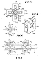
- FIG. 1 shown therein are two sets of four stationary electromagnets 10 1 , 12 1 , 14 1 , 16 1 and 10 2 , 12 2 , 14 2 , 16 2 located at each end of an elongated cylindrical housing 18 comprised of non-magnetic material which is adapted to accommodate an armature 20 in the form of a linear cylindrical shaft.
- the armature shaft 20 is adapted for both reciprocal and rotational motion within the housing 18.
- the shaft 20 is highly magnetic, at least in the vicinity of two sets of pole pieces 22 1 , 24 1 , 26 1 , 28 1 , and 22 2 , 24 2 , 26 2 , 28 2 so that the flux generated by respective coils 32 1 , 34 1 , 36 1 , 38 1 , and 32 2 , 34 2 , 36 2 , 38 2 is circulated through two housing wall sections 39, and 39 2 , respectively, in a closed path 30, and 30 2 respectively, through two series of air gaps 40 1 , 42 1 and 40 2 , 42 2 respectively, formed between the outer surface 43 of the shaft 20 and the pole piece faces.
- a magnetic attraction force is developed by each of the electromagnets in the respective pole pieces by applying a unidirectional (DC) current to the coils 32 1 , 34, ... 36 2 , 38 2 .
- DC unidirectional
- the system shown in Figure 1 is an active system in that positional information with respect to axial alignment of the shaft 20 is provided to excite opposing pairs of coils e.g., 32, and 36 1 by means of one of four like feedback control loops, to be described, with reference to Figure 9.
- the positional information at each end of the housing 18 is provided by two pairs of sensor devices which include transducers 48 1 , 50 1 , 48 2 , 50 2 . These transducers are placed at right angles to one another, aligned with and adjacent respective electromagnets 10 1 , 12, and 10 2 , 12 2 .
- the transducers may consist of eddy current sensor devices which include a probe tip, not shown, which extends into the interior of the housing 18 in close proximity to the outer surface 43 of the armature shaft 20.
- This type of sensor device is of a conventional design and comprises one component of a known eddy current sensor system, a typical example of which is a Probe Tip Model No. 300 marketed by the Bently Nevada Corporation.
- capacitive-type sensors may be employed.
- Position sensor 48 1 for example, is adapted to operate in conjunction with the electromagnets 10, and 14, which lie along one rectilinear axis whereas position sensor 50, operates in connection with electromagnets 12, and 16 1 , which lie along an axis perpendicular to the first axis.
- FIG. 2 the housing 18 is shown in cross section mounted between two support pedestals 52 and 54 which are secured to a base plate member 56.
- the two sets of electromagnets 10 1 , 10 2 , etc. are mounted on the housing 18 by two tubular type outer flange members 58 and 60, respectively, and a central flange member 62 which is also tubular in shape.
- the respective flange members include right angled circular flange sections 64, 66, 68 and 70 which are adapted to accept threaded hardware for securing the respective pole pieces thereto.
- the outer flange members 58 and 60 are securely fastened to the housing 18 and additionally include respective outwardly extending shield plates 72 and 74 which shield the position transducers 48 1 , 50, and 48 2 , 50 2 from the respective electromagnets which are located on the other side thereof.
- each transducer 48 1 , 48 2 , etc. includes a threaded outer wall which is adapted to engage and be held in place by nuts 80, 82 which also provide for positioning the tip of the transducers 48, and 48 2 within holes 84, and 84 2 provided in a wall of the housing 18.
- nuts 80, 82 which also provide for positioning the tip of the transducers 48, and 48 2 within holes 84, and 84 2 provided in a wall of the housing 18.
- the same structure is utilized for the orthogonally positioned transducers 50, and 50 2 shown in Figure 1.
- the armature shaft 20 includes enlarged cross sectional portions 86 and 88 in the region of the pole pieces 22 1 , 26, and 22 2 , 26 2 , respectively.
- the armature shaft 20, moreover, is comprised of magnetically permeable material throughout and accordingly the enlarged portions 86 and 88 provide a close magnetic coupling to the surrounding pole pieces.
- the cross sectional area of the shaft portions 86 and 88 is also made sufficiently large not to saturate; otherwise, a substantial amount of coil ampere turns would be required for the passage of the armature flux.
- the shaft material is typically comprised of cold rolled steel because it has a relatively high magnetic saturation level and as such a relatively small diameter shaft can pass a large amount of flux. Its relatively high permeability also gives a larger AC skin depth for AC flux penetration than, for example, pure iron.
- FIG. 1 While the orthogonality of the electromagnets is shown in Figure 1, it is further illustrated in Figure 3 wherein electromagnets 10, and 14, are shown opposing one another along the vertical axis while electromagnets 12, and 16 1 oppose one another along the horizontal axis.
- Figure 3 also illustrates the central longitudinal alignment of the shaft portion 86 within the housing 18 when suspended as well as the general shape of the pole pieces 22 1 , 24 1 , 26 1 and 28 1 , and their respective windings 32 1 , 34 1 , 36, and 38 1 .
- pole piece 22 As to the pole pieces themselves, they are all identical in construction.
- the pole piece 22, is a generally U-shaped, bifurcated member including leg portions 90 and 92 separated by a bight portion 93.
- the leg portions 90 and 92 are tapered downwardly toward concave pole faces 94 and 96, respectively, which have a radius just slightly larger than the inner surface of the housing 18.
- the tapering of the pole piece leg portions 90 and 92 provides a concentration of the flux whereas the curved pole faces 94 and 96i provide a constant air gap between the pole piece and the suspended shaft 20 as shown in Figures 1 and 3.
- the pole piece mid-section or bight portion 93 which accommodates a coil, not shown, and is relatively thick in the region 98a to avoid saturation and allow the flux to pass at a low flux density level through the poles faces 94 and 96 to the armature shaft 20.
- the tapered pole piece also serves to increase the magnetic suspension force of the bearing inasmuch as the suspension force is proportional to the square of the flux divided by the gap cross sectional area. Accordingly, the smaller the cross sectional area of the gap, the greater the attractive force.
- the pole pieces need not be tapered, however, to work effectively.
- the armature shaft 20 shown in the preferred embodiment of Figure 2, is comprised of a unitary member, it nevertheless includes a small diameter axial bore 85 which terminates in enlarged diameter end bore portions 87 and 89 which exist in the region of the position transducers 48 1 , 50, and 48 2 , 50 2 , respectively.
- the purpose of the bore portions 85, 87 and 89 is to reduce the weight of the suspended shaft 20 as much as possible. Accordingly, the diameter of the shaft 20 is further reduced in the intermediate region 91 shown in Figure 2.
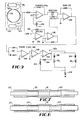
- armature shaft 20 Alternative configurations of the armature shaft 20 are shown in Figures 7 and 8.
- a relatively small diameter shaft member 20' which may be hollow, for example, includes a pair of magnetic sleeve members 98 and 100 fitted on the outer surface of the shaft in the region of the electromagnets, not shown.
- the shaft 20' need not be comprised of magnetically permeable material but may consist of non-magnetic material such as plastic.
- another configuration of the armature shaft comprises the configuration shown in Figure 8 wherein rererence numeral 20" denotes a relatively thin hollow tubular shaft consisting of magnetic material within which is placed a pair of internal sleeve members 102 and 104, also comprised of magnetic material. In both cases the region of the location of the electromagnets in the respective air gaps is enlarged so that magnetic saturation does not occur with the design of the particular magnetic circuit utilized.
- Figures 5 and 6 respectively provide a side planar and end view of a schematic representation of the invention.
- the armature shaft 20 is centrally located between the pole pieces 22 1 , 24 1 , 26 1 and 28 1 .
- flux paths 30 1 and 30 2 respectively, cross the air gaps 40 1 , 42 1 and 40 2 , 42 2 to the surface of the armature shaft 20 whereupon a magnetic attraction force is developed by each individual pole piece when a DC current is applied to the respective coils.
- the applied force F produces a cantilever effect on the shaft 20 which results in different forces being applied along the respective X ⁇ Y axes at the location of the two sets of electromagnets. Therefore, counter moments must be separately created by the eight pole pieces which also results in the bearing having an enhanced torsional stability and moment carrying capability.
- each coil can be energized in respect to shaft position information derived by one of the transducers 48 1 , 50 1 or 48 2 , 50 2 which are also located along the X-Y axes. While a minimum number of electromagnets required to constrain a shaft is three,-a a three pole configuration requires complex signal processing to direct current through the appropriate suspension coils. A four pole configuration therefore provides a simpler approach because coil excitation signals for only two axes (X and Y) are required.
- an axially magnetized bumper assembly 106 which is secured to a shaft 110 attached to one end of the shaft 20.
- the shaft 110 extends through one of a pair of stationary axially magnetized permanent magnets 112 and 114 which are held in place by a cylindrical housing 116 attached to the pedestal 52.
- the magnet 108 is poled to be repulsed by both of the stationary magnets 112 and 114 so that it is adapted to float therebetween.
- any undesired lateral, i.e., axial, displacement of the armature shaft 20 will be acted on by a restoring force developed by the assembly 106.
- a coil 118 is provided around the housing 116 which is excited by an AC current.
- an axial magnetic field will be applied to the bumper magnet 108 which will oscillate back and forth between the fixed magnets 112 and 114. Because it is attached to the armature shaft 20 by means of the rod 110, an oscillatory movement will be imparted to the shaft.
- the application of a DC signal to coil 118 will result in the shaft 20 achieving a fixed axial position.
- circuit configurations one of which is shown in Figure 9, is utilized for energizing the four pairs of mutually opposing windings along the horizontal (X) and vertical (Y) axes at both ends of the housing 18.
- the circuit configuration shown in Figure 9 is typically illustrative of the circuit utilized for implementing a closed loop feedback circuit for energizing the opposing windings 32 1 and 36 1 along the vertical or Y axis in response to positional information of the shaft sensed by the transducer 48 1 ,
- the transducer 48 forms one element of an eddy current sensor system 120 which, for example, may be a Proximeter Model No. 3000 manufactured by the Bently Nevada Corporation.
- the sensor system 120 includes an RF coil, not shown, located on the forward tip 82a of the transducer 48, which is placed adjacent the armature shaft 20 as shown in Figure 2.
- the RF coil is excited with a nominal frequency of, for example, 2 MHz from a circuit module 122 including an oscillator circuit, not shown.
- the coil in the tip 82a radiates a localized magnetic field pattern which produces eddy currents in the surface layer of the armature shaft 20 which "loads down" the RF coil.
- a resonant circuit in the circuit modules 122 changes its amplitude in response to the loading, whereupon an output signal appearing on lead 124 changes correspondingly.
- a cable 126 couples the transducer 48, to the circuit module 122.
- the cable 126 has a specified capacitance per unit length, it interacts with the resonant circuit elements inside the circuit module 122 and accordingly affects the nominal resonant frequency, which by varying the lengths of cable, the carrier frequency exciting the RF coil can be changed.
- the various transducers 48 and 50 Interference can occur between the various transducers 48 and 50 at each end of the housing 18 because the suspended armature shaft 20 acts like a coaxial transmission line.
- the respective transducer carrier frequencies are preferably offset by predetermined amount by the selection of different cable lengths.
- the sensor output signal which appears on circuit lead 124 is split into two circuit paths.
- One circuit path connects to a position comparator circuit 126a which includes an operational amplifier 128 having one input (-) coupled to the sensor signal, while the other input (+) is coupled to a variable DC reference signal provided by a potentiometer 130 coupled across a fixed DC voltage source, not shown.
- the operational amplifier 128 provides a difference signal output between the existing and desired positional inputs and thus generates an error signal which is directly proportional to the displacement of the armature shaft 20 from its central or axial position within the housing 18.
- the output signal from the operational amplifier 128, moreover, is positive for displacement of the armature shaft 20 in one direction while it is negative if the displacement is in the opposite direction.
- the other circuit path is coupled to a differentiator circuit 132 which includes a resistive-capacitive network 133 coupled to one input (-) of an operational amplifier 134 whose other input (+) is grounded.
- the output of the operational amplifier 134 accordingly comprises a signal which is proportional to velocity or rate of change of displacement of the armature shaft 20 from its desired position.
- the velocity signal is applied to one input (-) of an operational amplifier 136 whose output comprises one input to a summing circuit 138 which includes a resistive summing network 137 and an operational amplifier 139.
- the other input to the summing circuit 138 is the position signal from the comparator circuit 126a.
- the gain in the one or position channel determines the stiffness of the bearing while the gain in the other or velocity channel determines the dampening of the bearing.
- the gains in the respective position and velocity channels are determined by the component values associated with the various operational amplifiers and thus the output of operational amplifier 139 comprises a composite control signal which provides a suitable signal for properly energizing a pair of coils 32, and 36 1 .
- the forces acting on the armature shaft 20 are in phase with the output of the summing aplifier 139; however, two factors cause deviation from the ideal.
- eddy currents in the armature shaft 20 and in the core material of the pole pieces 22, and 26, associated with the windings 32, and 36 cause a phase shift between the current energizing the respective windings of the magnetic flux produced thereby.
- a phase corrector circuit 140 including a parallel resistive capacitive network 142 and two operational amplifiers 144 and 146 are therefore included in the circuitry shown in Figure 9 to partially correct this deviation.
- the second phase shift is caused by the inductance of the coils 32 1 and 36 1 which causes the current flowing therein to lag the voltage applied across them during excitation.
- This second deviation is overcome by a current feedback signal developed across a series resistor 148 coupled to like ends of the coil windings 32, and 361.
- This signal is fed back to one input (-) of a driver amplifier circuit 150 including an operational amplifier 152 whose other input (+) is connected to the output of operational amplifier 146.
- the driver amplifier 150 also includes a voltage feedback provided by a resistor 154 coupled between the output and the negative (-) input of the operational amplifier 152 to limit the voltage gain of the driver amplifier circuit 150 in order to insure stability of the current feedback.
- the output of the operational amplifier 152 comprises a signal current which is channeled to the pair of Y axis electromagnet coils 32 1 and 36 1 by the diodes 156 and 158 which are oppositely poled with respect to one another so that the positive output from the driver amplifier circuit 150 causes coil 32, to be energized thereby attracting the shaft 20 upwardly along the Y axis while a negative output therefrom energizes the coil 361 which causes a downward attraction of the shaft 20 on the Y axis.
- the electromagnets 10, and 14 will be properly energized to drive the shaft 20 in the proper direction until a zero error signal is produced at the output of the comparator circuit 126a.
Landscapes
- Engineering & Computer Science (AREA)
- General Engineering & Computer Science (AREA)
- Mechanical Engineering (AREA)
- Physics & Mathematics (AREA)
- Electromagnetism (AREA)
- Magnetic Bearings And Hydrostatic Bearings (AREA)
Claims (8)
caractérisé en ce que les moyens (106) pour commander la position axiale de l'arbre (20) comportent un butoir (106, 108, 110, 112, 114) aimanté axialement comprenant deux aimants stationnaires (112, 114) écartés l'un de l'autre et maintenus en place dans un carter (116) et un aimant (108) assujetti à l'arbre (20, 110) pour un mouvement axial important entre les deux aimants (112, 114),
et en ce que l'arbre (20) comporte des régions déterminées où le volume du matériau magnétique par unité de longueur d'arbre (20) est plus grand que dans le reste de l'arbre, lesdites régions étant d'une longueur telle qu'elles restent sous l'influence des moyens électromagnétiques pendant ledit mouvement axial important de l'arbre (20).
Applications Claiming Priority (2)
| Application Number | Priority Date | Filing Date | Title |
|---|---|---|---|
| US22021380A | 1980-12-24 | 1980-12-24 | |
| US220213 | 1980-12-24 |
Publications (2)
| Publication Number | Publication Date |
|---|---|
| EP0054617A1 EP0054617A1 (fr) | 1982-06-30 |
| EP0054617B1 true EP0054617B1 (fr) | 1987-01-28 |
Family
ID=22822564
Family Applications (1)
| Application Number | Title | Priority Date | Filing Date |
|---|---|---|---|
| EP19810107072 Expired EP0054617B1 (fr) | 1980-12-24 | 1981-09-09 | Paliers magnétiques linéaires |
Country Status (6)
| Country | Link |
|---|---|
| EP (1) | EP0054617B1 (fr) |
| JP (1) | JPS57146913A (fr) |
| AU (1) | AU547809B2 (fr) |
| CA (1) | CA1164515A (fr) |
| DE (1) | DE3175878D1 (fr) |
| IE (1) | IE52454B1 (fr) |
Families Citing this family (18)
| Publication number | Priority date | Publication date | Assignee | Title |
|---|---|---|---|---|
| US4389849A (en) * | 1981-10-02 | 1983-06-28 | Beggs James M Administrator Of | Stirling cycle cryogenic cooler |
| DE3378341D1 (en) * | 1982-06-30 | 1988-12-01 | Philips Nv | Magnetically suspended linear motor |
| FR2570488B1 (fr) * | 1984-09-19 | 1987-01-09 | Europ Propulsion | Dispositif de detection magnetique des deplacements radiaux d'un rotor |
| JPS6185060A (ja) * | 1984-09-29 | 1986-04-30 | Toshiba Corp | 非接触位置決め装置 |
| JPH0637895B2 (ja) * | 1986-09-12 | 1994-05-18 | 株式会社日立製作所 | 電磁軸受制御装置 |
| FR2609123A1 (fr) * | 1986-12-31 | 1988-07-01 | Mecanique Magnetique Sa | Palier fluide hybride a raideur modifiee par effet electromagnetique |
| FR2625048B1 (fr) * | 1987-12-16 | 1990-06-01 | Aerospatiale | Moteur electrique a haut rendement et a faible ondulation de couple |
| GB2221064B (en) * | 1988-07-19 | 1992-04-29 | Glacier Metal Co Ltd | Improvements in and relating to bearings |
| US5111102A (en) * | 1989-05-25 | 1992-05-05 | Meeks Crawford R | Magnetic bearing structure |
| ATE128443T1 (de) * | 1989-06-07 | 1995-10-15 | Partek Ab | Spinnrad zur herstellung von glasfasern mittels zentrifugalkraft. |
| EP0523002B1 (fr) * | 1991-07-11 | 1996-02-28 | LAUBE, Hans-Jürgen | Aimant composé comprenant plusieurs aimants individuels et palier magnétique permanent avec un aimant composé comprenant plusieurs aimants individuels |
| FR2720456B1 (fr) * | 1994-05-25 | 1996-08-14 | Aerospatiale | Palier magnétique radial actif sans aimants et à faible trainée. |
| US5627421A (en) * | 1994-10-28 | 1997-05-06 | Barber-Colman Company | High efficiency drive circuit for an active magnetic bearing system |
| EP0845084B1 (fr) | 1995-08-18 | 2004-03-03 | LUST ANTRIEBSTECHNIK GmbH | Palier magnetique actif radial et son procede de fonctionnement |
| GB9619854D0 (en) * | 1996-09-24 | 1996-11-06 | British Nuclear Fuels Plc | Electromagnetic suspension apparatus and method of controlling the same |
| GB2363864B (en) * | 2000-06-23 | 2004-08-18 | Rolls Royce Plc | A control arrangement |
| CN105114457B (zh) * | 2015-08-24 | 2017-06-09 | 南京邮电大学 | 一种轴向径向电励磁磁轴承 |
| CN112610604B (zh) * | 2020-12-30 | 2022-10-14 | 四川龙天精工科技有限公司 | 一种基于电磁力调节的气磁混合支承误差补偿方法 |
Family Cites Families (6)
| Publication number | Priority date | Publication date | Assignee | Title |
|---|---|---|---|---|
| DE330994C (de) * | 1919-04-26 | 1920-12-28 | Franz Van Treeck | Elastisches Lager |
| US3112962A (en) * | 1962-01-17 | 1963-12-03 | Gen Motors Corp | Magnetic suspension system |
| US3243238A (en) * | 1962-07-20 | 1966-03-29 | Lyman Joseph | Magnetic suspension |
| US3787100A (en) * | 1972-12-11 | 1974-01-22 | Armement Direction Tech Engins | Devices including rotating members supported by magnetic bearings |
| DE2420814C3 (de) * | 1974-04-30 | 1980-10-16 | Padana Ag, Zug (Schweiz) | Magnetlager mit einem Lagerelement zur Festlegung eines translatorischen Freiheitsgrades |
| US4180946A (en) * | 1975-10-02 | 1980-01-01 | Maurice Brunet | Tool holding spindle assembly particularly for a grinding machine |
-
1981
- 1981-09-04 AU AU74959/81A patent/AU547809B2/en not_active Ceased
- 1981-09-04 IE IE205881A patent/IE52454B1/en unknown
- 1981-09-08 CA CA000385352A patent/CA1164515A/fr not_active Expired
- 1981-09-09 DE DE8181107072T patent/DE3175878D1/de not_active Expired
- 1981-09-09 EP EP19810107072 patent/EP0054617B1/fr not_active Expired
- 1981-09-16 JP JP14481681A patent/JPS57146913A/ja active Granted
Also Published As
| Publication number | Publication date |
|---|---|
| IE812058L (en) | 1982-06-24 |
| AU547809B2 (en) | 1985-11-07 |
| DE3175878D1 (en) | 1987-03-05 |
| CA1164515A (fr) | 1984-03-27 |
| AU7495981A (en) | 1982-07-01 |
| JPS613968B2 (fr) | 1986-02-06 |
| JPS57146913A (en) | 1982-09-10 |
| IE52454B1 (en) | 1987-11-11 |
| EP0054617A1 (fr) | 1982-06-30 |
Similar Documents
| Publication | Publication Date | Title |
|---|---|---|
| US4473259A (en) | Linear magnetic bearings | |
| EP0054617B1 (fr) | Paliers magnétiques linéaires | |
| DE69635841T2 (de) | Integriertes magnetisches schwebe- und drehsystem | |
| EP0121007B1 (fr) | Un capteur de position combiné avec un vérin magnétique | |
| US6268674B1 (en) | Magnetic bearing apparatus | |
| US4620752A (en) | Magnetic bearing having triaxial position stabilization | |
| US4583794A (en) | Electromagnetic bearing | |
| EP0364993B1 (fr) | Système de palier magnétique | |
| US3976339A (en) | Magnetic suspension apparatus | |
| US5170104A (en) | Linear actuator control system for platform stabilization | |
| US4090745A (en) | Magnetic suspension with magnetic stiffness augmentation | |
| US4597613A (en) | Electromagnetic bearing | |
| US9559565B2 (en) | Homopolar permanent-magnet-biased action magnetic bearing with an integrated rotational speed sensor | |
| US6208051B1 (en) | Spindle apparatus | |
| JPH08505826A (ja) | 直接トルク制御モーメント・ジャイロスコープ | |
| US4983869A (en) | Magnetic bearing | |
| EP0880653B1 (fr) | Systeme de rotor comprenant un transducteur pour la vitesse de deplacement axial | |
| CA1231255A (fr) | Bobine pour mesurer par induction la vitesse de mouvement d'un corps magnetise | |
| US4891983A (en) | Inductively coupled force balance instrument | |
| Kant et al. | A 6-DoF position sensor for bearingless slice motors | |
| Goldowskiy | Linear magnetic bearings | |
| JP3058451B2 (ja) | 磁気的に取付けられた制振はずみ車 | |
| JP2005061580A (ja) | 磁気軸受 | |
| CA1234203A (fr) | Systeme de sustentation magnetique | |
| US4355541A (en) | Magnetic gyroscope |
Legal Events
| Date | Code | Title | Description |
|---|---|---|---|
| PUAI | Public reference made under article 153(3) epc to a published international application that has entered the european phase |
Free format text: ORIGINAL CODE: 0009012 |
|
| AK | Designated contracting states |
Designated state(s): BE CH DE FR GB IT NL SE |
|
| 17P | Request for examination filed |
Effective date: 19821223 |
|
| GRAA | (expected) grant |
Free format text: ORIGINAL CODE: 0009210 |
|
| AK | Designated contracting states |
Kind code of ref document: B1 Designated state(s): BE CH DE FR GB IT LI NL SE |
|
| ITF | It: translation for a ep patent filed | ||
| REF | Corresponds to: |
Ref document number: 3175878 Country of ref document: DE Date of ref document: 19870305 |
|
| PGFP | Annual fee paid to national office [announced via postgrant information from national office to epo] |
Ref country code: NL Payment date: 19870930 Year of fee payment: 7 |
|
| PLBI | Opposition filed |
Free format text: ORIGINAL CODE: 0009260 |
|
| 26 | Opposition filed |
Opponent name: ARTHUR PFEIFFER VAKUUMTECHNIK WETZLAR GMBH Effective date: 19871024 |
|
| NLR1 | Nl: opposition has been filed with the epo |
Opponent name: ARTHUR PFEIFFER VAKUUMTECHNIK WETZLAR GMBH |
|
| PG25 | Lapsed in a contracting state [announced via postgrant information from national office to epo] |
Ref country code: SE Effective date: 19880910 |
|
| PG25 | Lapsed in a contracting state [announced via postgrant information from national office to epo] |
Ref country code: LI Effective date: 19880930 Ref country code: CH Effective date: 19880930 Ref country code: BE Effective date: 19880930 |
|
| BERE | Be: lapsed |
Owner name: NATIONAL AERONAUTICS AND SPACE ADMINISTRATION Effective date: 19880930 |
|
| PG25 | Lapsed in a contracting state [announced via postgrant information from national office to epo] |
Ref country code: NL Effective date: 19890401 |
|
| PLBN | Opposition rejected |
Free format text: ORIGINAL CODE: 0009273 |
|
| STAA | Information on the status of an ep patent application or granted ep patent |
Free format text: STATUS: OPPOSITION REJECTED |
|
| NLV4 | Nl: lapsed or anulled due to non-payment of the annual fee | ||
| REG | Reference to a national code |
Ref country code: CH Ref legal event code: PL |
|
| 27O | Opposition rejected |
Effective date: 19890129 |
|
| PGFP | Annual fee paid to national office [announced via postgrant information from national office to epo] |
Ref country code: GB Payment date: 19890831 Year of fee payment: 9 |
|
| PGFP | Annual fee paid to national office [announced via postgrant information from national office to epo] |
Ref country code: FR Payment date: 19890914 Year of fee payment: 9 |
|
| PGFP | Annual fee paid to national office [announced via postgrant information from national office to epo] |
Ref country code: DE Payment date: 19890915 Year of fee payment: 9 |
|
| PG25 | Lapsed in a contracting state [announced via postgrant information from national office to epo] |
Ref country code: GB Effective date: 19900909 |
|
| GBPC | Gb: european patent ceased through non-payment of renewal fee | ||
| PG25 | Lapsed in a contracting state [announced via postgrant information from national office to epo] |
Ref country code: FR Effective date: 19910530 |
|
| PG25 | Lapsed in a contracting state [announced via postgrant information from national office to epo] |
Ref country code: DE Effective date: 19910601 |
|
| REG | Reference to a national code |
Ref country code: FR Ref legal event code: ST |
|
| EUG | Se: european patent has lapsed |
Ref document number: 81107072.1 Effective date: 19890614 |