EP0054626A1 - Détecteur du courant magnétorésistif - Google Patents
Détecteur du courant magnétorésistif Download PDFInfo
- Publication number
- EP0054626A1 EP0054626A1 EP81107420A EP81107420A EP0054626A1 EP 0054626 A1 EP0054626 A1 EP 0054626A1 EP 81107420 A EP81107420 A EP 81107420A EP 81107420 A EP81107420 A EP 81107420A EP 0054626 A1 EP0054626 A1 EP 0054626A1
- Authority
- EP
- European Patent Office
- Prior art keywords
- bridge
- current
- thin film
- thin films
- differential amplifier
- Prior art date
- Legal status (The legal status is an assumption and is not a legal conclusion. Google has not performed a legal analysis and makes no representation as to the accuracy of the status listed.)
- Granted
Links
Images
Classifications
-
- G—PHYSICS
- G01—MEASURING; TESTING
- G01R—MEASURING ELECTRIC VARIABLES; MEASURING MAGNETIC VARIABLES
- G01R33/00—Arrangements or instruments for measuring magnetic variables
- G01R33/02—Measuring direction or magnitude of magnetic fields or magnetic flux
- G01R33/06—Measuring direction or magnitude of magnetic fields or magnetic flux using galvano-magnetic devices
- G01R33/09—Magnetoresistive devices
Definitions
- a current detector of the type mentioned in the preamble of claim 1 is known (IEEE Transactions on Magnetics, Nov. 1976, pages 813-815), in which each of the four bridge elements consists of a pair of magnetoresistive thin films which are magnetostatically coupled to one another.
- the two thin films of a pair of thin films are selected to have different thicknesses so that the opposing changes in resistance of the two thin films do not cancel each other out and a satisfactorily large output signal is produced.
- the object of the invention specified in claim 1 is to improve a current detector of the type mentioned in such a way that it is distinguished by a simpler structure and better linearity.
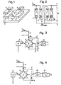
- 1 to 4 mean four thin films made of ferromagnetic magnetoresistive material.
- the thin films 1 and 4 lie in a first common plane and the thin films 2 and 3 in a second plane parallel to the first plane.
- the thin film 1 is congruent over the thin film 2 and the thin film 4 is congruent with the thin film 3.
- the thin films 1, 2 and the thin films 4, 3 are of the same thickness and each form a thin film pair, ie they are magnetostatically coupled to one another and therefore very low Distance, isolated from each other by a layer not shown, arranged one above the other.
- the thin films 1 to 4 form an electrical bridge 5, in which each of the four bridge elements consists of a single thin film and thus the thin films 1, 2 and 4, 3 of a pair of thin films each belong to different bridge elements.
- the thin films 2 and 3 are drawn with dashed lines in FIG. 2 to indicate that they lie under the thin film 1 and 4, respectively.
- the two rear ends of the thin films 1, 2 in the drawing and the two front ends of the thin films 3, 4 are connected to a voltage or current source 6 (FIG. 3) which feeds a current I o into the bridge 5.
- the front end of the thin film 2 and the rear end of the thin film 4 are connected to an output terminal 7 and the front end of the thin film 1 and the rear end of the thin film 3 to an output terminal 8 of the bridge 5.
- the bridge 5 is exposed to an external magnetic field H a .
- This is generated by a measuring current I m , which flows in a measuring conductor 9 ′ in the direction of the easy magnetic axis EA of the thin films 1 to 4.
- a flat conductor track or a coil can be used as the measuring conductor 9, for example, the bridge 5 being arranged in a zone in which the measuring conductor 9 generates a magnetic field H a which is as homogeneous as possible and which magnetizes the thin films 1 to 4 in the direction of their hard magnetic axis HA .
- the current 1 ⁇ 2I o flowing in the thin film 2 produces in the thin film 1 a magnetic auxiliary field + H b directed to the left in the drawing, whereby the magnetization vector M in the thin film 1 is rotated counterclockwise by a certain angle from the easy magnetic axis EA.
- the current 1 ⁇ 2I o flowing in the thin film 3 creates an auxiliary field + H b and a rotation of the magnetization vector M counterclockwise in the thin film 4.
- the current 1 ⁇ 2I o flowing in the thin film 1 or 4 causes an auxiliary field — H b and a rotation of the magnetization vector M in the thin film 2 or 3 clockwise.
- the resulting change in resistance is the same in all thin films 1 to 4 and the bridge 5 remains in equilibrium.
- the bridge 5 is advantageously connected to a differential amplifier 10, which has a constant amplification factor and amplifies the bridge voltage U b to a level suitable for measurement or display.
- the latter is fed in FIG. 4 from an alternating voltage or alternating current source 11 with a preferably rectangular curve.
- a filter 12 is connected downstream of the differential amplifier 10 connected to the output terminals 7, 8 of the bridge 5.
- the auxiliary fields H b also reverse their direction, so that, as can be seen from equation (1), the bridge voltage U b does not change its sign.
- a voltage U is produced which is proportional to the external magnetic field H and is freed from offset errors of the bridge 5.
- two filters are advantageously used, one of which is connected between the output terminal 7 and the first input of the differential amplifier 10 and the other between the output terminal 8 and the second input of the differential amplifier 10. This has the advantage that the differential amplifier 10 does not have to process the so-called common mode voltage of the bridge 5 or steep edges of the bridge voltage U caused by asymmetries of the bridge 5 and therefore does not have to be broadband.
- the alternating current supply of the bridge 5 is advantageously realized in that the bridge 5 is connected to a direct current source via a pole-reversal switch. This ensures in a simple manner that the amount of current I o is the same in both directions of flow.
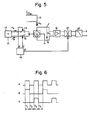
- a direct current source 13 feeds the bridge 5 via a switch 14 with a positive current + I o and via a switch 15 with a negative current -I.
- a control circuit 18 supplies periodic signals A, B and C for controlling the synchronous detector 17 and the switches 14, 15 (FIG. 6).
- switch 14 is closed and switch 15 is open.
- the bridge 5 is supplied with the current + I o and the synchronous detector 17 switches the amplified bridge voltage U b and any offset voltage of the differential amplifier 16 non-inverted to the filter 12.
- T 3 only the switch 15 is closed and the amplified bridge voltage U b and the offset voltage of the differential amplifier 16 are switched to the filter 12 non-inverted.
- both switches 14, 15 are again opened and the offset voltage of the differential amplifier 16 reaches the filter 12 inverted.
- the current I m is therefore measured in each case during the time intervals T 1 and T 3 .
- the current detector described has only four thin films 1 to 4, which are also used to generate the necessary auxiliary fields H b , and is therefore distinguished by a simple structure. With galvanic isolation, it provides a linear image of the measuring current I m , is suitable for measuring AC and DC currents and can be manufactured as an iron-core converter using integrated circuit technology. By connecting an additional conductor track in parallel, which is sufficiently distant from the bridge 5, a current divider can be formed for the measuring current I m and the measuring range of the current detector can thereby be preselected within wide limits.
Landscapes
- Physics & Mathematics (AREA)
- Condensed Matter Physics & Semiconductors (AREA)
- General Physics & Mathematics (AREA)
- Measuring Magnetic Variables (AREA)
- Measuring Instrument Details And Bridges, And Automatic Balancing Devices (AREA)
Priority Applications (1)
| Application Number | Priority Date | Filing Date | Title |
|---|---|---|---|
| AT81107420T ATE12319T1 (de) | 1980-12-24 | 1981-09-18 | Magnetoresistiver stromdetektor. |
Applications Claiming Priority (2)
| Application Number | Priority Date | Filing Date | Title |
|---|---|---|---|
| CH9567/80A CH651672A5 (de) | 1980-12-24 | 1980-12-24 | Magnetoresistiver stromdetektor. |
| CH9567/80 | 1980-12-24 |
Publications (2)
| Publication Number | Publication Date |
|---|---|
| EP0054626A1 true EP0054626A1 (fr) | 1982-06-30 |
| EP0054626B1 EP0054626B1 (fr) | 1985-03-20 |
Family
ID=4353332
Family Applications (1)
| Application Number | Title | Priority Date | Filing Date |
|---|---|---|---|
| EP81107420A Expired EP0054626B1 (fr) | 1980-12-24 | 1981-09-18 | Détecteur du courant magnétorésistif |
Country Status (5)
| Country | Link |
|---|---|
| US (1) | US4464625A (fr) |
| EP (1) | EP0054626B1 (fr) |
| AT (1) | ATE12319T1 (fr) |
| CH (1) | CH651672A5 (fr) |
| DE (1) | DE3169405D1 (fr) |
Cited By (3)
| Publication number | Priority date | Publication date | Assignee | Title |
|---|---|---|---|---|
| DE3416244A1 (de) * | 1984-05-02 | 1985-11-07 | Siemens AG, 1000 Berlin und 8000 München | Sensor zur messung eines elektrischen stromes |
| AU640434B2 (en) * | 1990-02-03 | 1993-08-26 | Alcatel N.V. | Magnetic-field sensor |
| RU2134890C1 (ru) * | 1997-07-08 | 1999-08-20 | Войсковая часть 35533 | Устройство регистрации магнитного поля |
Families Citing this family (33)
| Publication number | Priority date | Publication date | Assignee | Title |
|---|---|---|---|---|
| US4754219A (en) * | 1985-09-09 | 1988-06-28 | General Electric Company | Low cost self-contained transformerless solid state electronic watthour meter having thin film ferromagnetic current sensor |
| JPS63500961A (ja) * | 1985-09-14 | 1988-04-07 | エルゲーツエット・ランディス・ウント・ギール・ツーク・アクチエンゲゼルシャフト | 静的積算電気計器の変流装置 |
| KR910004261B1 (ko) * | 1987-04-09 | 1991-06-25 | 후지쓰 가부시끼가이샤 | 자전 변환 소자를 이용한 검지기 |
| JP2581421Y2 (ja) * | 1991-06-17 | 1998-09-21 | 株式会社村田製作所 | 磁気センサ |
| US10361802B1 (en) | 1999-02-01 | 2019-07-23 | Blanding Hovenweep, Llc | Adaptive pattern recognition based control system and method |
| US8352400B2 (en) | 1991-12-23 | 2013-01-08 | Hoffberg Steven M | Adaptive pattern recognition based controller apparatus and method and human-factored interface therefore |
| JPH062115U (ja) * | 1992-06-19 | 1994-01-14 | ヤマハ株式会社 | 磁気式検出装置 |
| US5404102A (en) * | 1993-01-06 | 1995-04-04 | General Motors Corporation | Method and apparatus for electrically exciting a magneto-resistor device |
| DE4300605C2 (de) * | 1993-01-13 | 1994-12-15 | Lust Electronic Systeme Gmbh | Sensorchip |
| DE4436876A1 (de) * | 1994-10-15 | 1996-04-18 | Lust Antriebstechnik Gmbh | Sensorchip |
| DE19507303A1 (de) * | 1995-03-02 | 1996-09-05 | Siemens Ag | Sensoreinrichtung mit einer Brückenschaltung von magnetoresistiven Sensorelementen |
| DE19526983C2 (de) * | 1995-07-25 | 2000-09-07 | Fraunhofer Ges Forschung | Verfahren zur Messung und Überprüfung der elektrischen Stromverteilung in hochintegrierten Bauteilen |
| DE19619806A1 (de) * | 1996-05-15 | 1997-11-20 | Siemens Ag | Magnetfeldempfindliche Sensoreinrichtung mit mehreren GMR-Sensorelementen |
| US5936400A (en) * | 1996-12-23 | 1999-08-10 | Federal Products Co. | Magnetoresistive displacement sensor and variable resistor using a moving domain wall |
| EP0855599A3 (fr) * | 1997-01-24 | 2001-05-02 | Siemens Aktiengesellschaft | Compas électronique |
| RU2152046C1 (ru) * | 1998-10-26 | 2000-06-27 | Институт проблем управления РАН | Способ уменьшения воздействия гистерезиса на результаты измерения магнитного поля |
| US7904187B2 (en) | 1999-02-01 | 2011-03-08 | Hoffberg Steven M | Internet appliance system and method |
| US6445171B2 (en) * | 1999-10-29 | 2002-09-03 | Honeywell Inc. | Closed-loop magnetoresistive current sensor system having active offset nulling |
| US6433629B2 (en) * | 2000-01-24 | 2002-08-13 | Microstrain, Inc. | Micropower differential sensor measurement |
| WO2005033716A1 (fr) * | 2003-10-01 | 2005-04-14 | Eaton Corporation | Systeme et procede de detection de courant faisant appel a la detection de courant anti-differentielle et a correction d'erreurs |
| JP4360998B2 (ja) * | 2004-10-01 | 2009-11-11 | Tdk株式会社 | 電流センサ |
| JP4105145B2 (ja) * | 2004-11-30 | 2008-06-25 | Tdk株式会社 | 電流センサ |
| JP4105147B2 (ja) * | 2004-12-06 | 2008-06-25 | Tdk株式会社 | 電流センサ |
| US7064558B1 (en) * | 2004-12-16 | 2006-06-20 | Honeywell International Inc. | Millivolt output circuit for use with programmable sensor compensation integrated circuits |
| JP4224483B2 (ja) * | 2005-10-14 | 2009-02-12 | Tdk株式会社 | 電流センサ |
| US7528592B2 (en) * | 2006-05-31 | 2009-05-05 | Caterpillar Inc. | Magnetoresistive sensor for current sensing |
| US7388372B2 (en) * | 2006-05-31 | 2008-06-17 | Caterpillar Inc. | Electrical system with magnetoresistive sensors |
| JP2010500547A (ja) * | 2006-08-09 | 2010-01-07 | コーニンクレッカ フィリップス エレクトロニクス エヌ ヴィ | マイクロチップの磁気センサー装置 |
| US20100024698A1 (en) * | 2008-07-30 | 2010-02-04 | Headwaters Energy Services Corporation | METHOD FOR REDUCING NOx DURING COMBUSTION OF COAL IN A BURNER BY OPTIMIZING COMBUSTION AIR FLOW |
| CN102866279A (zh) * | 2011-07-04 | 2013-01-09 | 新科实业有限公司 | 电流传感器装置 |
| US8829901B2 (en) * | 2011-11-04 | 2014-09-09 | Honeywell International Inc. | Method of using a magnetoresistive sensor in second harmonic detection mode for sensing weak magnetic fields |
| US20130334531A1 (en) * | 2012-06-15 | 2013-12-19 | Franz Jost | Systems and methods for measuring temperature and current in integrated circuit devices |
| EP3244217B1 (fr) * | 2013-10-17 | 2019-05-22 | Osaka City University | Appareil de mesure de courant électrique |
Citations (4)
| Publication number | Priority date | Publication date | Assignee | Title |
|---|---|---|---|---|
| US3546579A (en) * | 1968-10-22 | 1970-12-08 | Sperry Rand Corp | Thin-ferromagnetic-film magnetoresistance magnetometer sensitive to easy axis field components and biased to be insensitive to hard axis field components |
| US3555310A (en) * | 1967-10-24 | 1971-01-12 | Siemens Ag | Apparatus and method for reducing the inverse of a hall generator |
| US3649912A (en) * | 1968-04-10 | 1972-03-14 | Tokyo Shibaura Electric Co | Direct current transformer employing magnetoresistance diodes for use in current measurement |
| US3820089A (en) * | 1971-11-16 | 1974-06-25 | Bell Canada Northern Electric | Magnetic bubble domain detection |
Family Cites Families (2)
| Publication number | Priority date | Publication date | Assignee | Title |
|---|---|---|---|---|
| SU598000A1 (ru) * | 1976-06-14 | 1978-03-15 | Специальное Проектно-Конструкторское И Технологическое Бюро Малых Электрических Машин Объединения "Эльфа" | Устройство дл измерени напр женности магнитного пол |
| CH651151A5 (de) * | 1979-11-27 | 1985-08-30 | Landis & Gyr Ag | Messwandler zum messen eines insbesondere von einem messstrom erzeugten magnetfeldes. |
-
1980
- 1980-12-24 CH CH9567/80A patent/CH651672A5/de not_active IP Right Cessation
-
1981
- 1981-09-18 DE DE8181107420T patent/DE3169405D1/de not_active Expired
- 1981-09-18 AT AT81107420T patent/ATE12319T1/de not_active IP Right Cessation
- 1981-09-18 EP EP81107420A patent/EP0054626B1/fr not_active Expired
- 1981-12-18 US US06/331,981 patent/US4464625A/en not_active Expired - Fee Related
Patent Citations (4)
| Publication number | Priority date | Publication date | Assignee | Title |
|---|---|---|---|---|
| US3555310A (en) * | 1967-10-24 | 1971-01-12 | Siemens Ag | Apparatus and method for reducing the inverse of a hall generator |
| US3649912A (en) * | 1968-04-10 | 1972-03-14 | Tokyo Shibaura Electric Co | Direct current transformer employing magnetoresistance diodes for use in current measurement |
| US3546579A (en) * | 1968-10-22 | 1970-12-08 | Sperry Rand Corp | Thin-ferromagnetic-film magnetoresistance magnetometer sensitive to easy axis field components and biased to be insensitive to hard axis field components |
| US3820089A (en) * | 1971-11-16 | 1974-06-25 | Bell Canada Northern Electric | Magnetic bubble domain detection |
Non-Patent Citations (1)
| Title |
|---|
| IEEE TRANSACTIONS ON MAGNETICS, Band MAG-12, Nr. 6, November 1976, New York (US) C.H. BAJOREK et al.: "A permalloy current sensor" Seiten 813-815 * |
Cited By (3)
| Publication number | Priority date | Publication date | Assignee | Title |
|---|---|---|---|---|
| DE3416244A1 (de) * | 1984-05-02 | 1985-11-07 | Siemens AG, 1000 Berlin und 8000 München | Sensor zur messung eines elektrischen stromes |
| AU640434B2 (en) * | 1990-02-03 | 1993-08-26 | Alcatel N.V. | Magnetic-field sensor |
| RU2134890C1 (ru) * | 1997-07-08 | 1999-08-20 | Войсковая часть 35533 | Устройство регистрации магнитного поля |
Also Published As
| Publication number | Publication date |
|---|---|
| EP0054626B1 (fr) | 1985-03-20 |
| DE3169405D1 (en) | 1985-04-25 |
| ATE12319T1 (de) | 1985-04-15 |
| CH651672A5 (de) | 1985-09-30 |
| US4464625A (en) | 1984-08-07 |
Similar Documents
| Publication | Publication Date | Title |
|---|---|---|
| EP0054626B1 (fr) | Détecteur du courant magnétorésistif | |
| DE3133908C2 (de) | Kompensierter Meßstromwandler | |
| DE3148754C2 (fr) | ||
| DE2911733C2 (fr) | ||
| DE4319146C2 (de) | Magnetfeldsensor, aufgebaut aus einer Ummagnetisierungsleitung und einem oder mehreren magnetoresistiven Widerständen | |
| CH651671A5 (de) | Anordnung zur messung elektrischer leistung oder energie. | |
| DE102013022432B4 (de) | Hall-Sensoren und Abfühlverfahren | |
| DE19520206C2 (de) | Magnetfeldsensor mit einer Brückenschaltung von magnetoresistiven Brückenelementen | |
| EP0030041A1 (fr) | Transformateur de mesure, notamment d'un champ magnétique généré par un courant de mesure | |
| DE4423429A1 (de) | Stromsensor nach dem Kompensationsprinzip | |
| DE2749784A1 (de) | Multiplizierschaltung, insbesondere fuer wattstundenzaehler | |
| DE3102998C2 (de) | Anordnung zur Messung elektrischer Leistung mit einem Multiplizierer | |
| DE2852567C2 (de) | Verstärker mit einem ersten und einem zweiten Verstärkerelement | |
| DE29714612U1 (de) | Strom-Meßeinrichtung | |
| DE2944364C2 (de) | Anordnung zur Messung einer Größe, die einen Feldeffekttransistor beeinflußt | |
| DE4318716A1 (de) | Magnetfeldsensor in Form einer Brückenschaltung | |
| DE4330290A1 (de) | Vorrichtung zur Messung des Stroms einer ein Meßrohr durchströmenden Flüssigkeit | |
| DE2743954A1 (de) | Verfahren zur messung des stroms einer fluessigkeit mittels eines induktiven stroemungsmessers | |
| DE4219908A1 (de) | Ferromagnetische widerstandseinheit in vollweg-brueckenschaltung | |
| DE2714142A1 (de) | Einrichtung zur messung eines magnetflusses | |
| DE2219780A1 (de) | Schaltanordnung zum messen auch sehr schwacher magnetischer wechselfelder | |
| DE1791027A1 (de) | Verfahren zum Orten eines Fehlers einer elektrischen Leitung | |
| DE2733792C2 (de) | Verfahren und Schalteinrichtung zur Kompensationsverstärkung periodischer oder getakteter elektrischer Meßsignale | |
| DE2102047A1 (de) | Verstarkeranordnung | |
| DE2950369C2 (de) | Schaltungsanordnung zur Verschiebung des Ausgangsstrombereich es eines Operationsverstärkers |
Legal Events
| Date | Code | Title | Description |
|---|---|---|---|
| PUAI | Public reference made under article 153(3) epc to a published international application that has entered the european phase |
Free format text: ORIGINAL CODE: 0009012 |
|
| AK | Designated contracting states |
Designated state(s): AT DE FR GB IT NL |
|
| 17P | Request for examination filed |
Effective date: 19821001 |
|
| ITF | It: translation for a ep patent filed | ||
| GRAA | (expected) grant |
Free format text: ORIGINAL CODE: 0009210 |
|
| AK | Designated contracting states |
Designated state(s): AT DE FR GB IT NL |
|
| REF | Corresponds to: |
Ref document number: 12319 Country of ref document: AT Date of ref document: 19850415 Kind code of ref document: T |
|
| REF | Corresponds to: |
Ref document number: 3169405 Country of ref document: DE Date of ref document: 19850425 |
|
| ET | Fr: translation filed | ||
| PLBE | No opposition filed within time limit |
Free format text: ORIGINAL CODE: 0009261 |
|
| STAA | Information on the status of an ep patent application or granted ep patent |
Free format text: STATUS: NO OPPOSITION FILED WITHIN TIME LIMIT |
|
| 26N | No opposition filed | ||
| ITPR | It: changes in ownership of a european patent |
Owner name: OFFERTA DI LICENZA AL PUBBLICO |
|
| REG | Reference to a national code |
Ref country code: GB Ref legal event code: 746 |
|
| REG | Reference to a national code |
Ref country code: FR Ref legal event code: DL |
|
| PGFP | Annual fee paid to national office [announced via postgrant information from national office to epo] |
Ref country code: GB Payment date: 19900820 Year of fee payment: 10 |
|
| PGFP | Annual fee paid to national office [announced via postgrant information from national office to epo] |
Ref country code: FR Payment date: 19900906 Year of fee payment: 10 |
|
| PGFP | Annual fee paid to national office [announced via postgrant information from national office to epo] |
Ref country code: AT Payment date: 19900910 Year of fee payment: 10 |
|
| ITTA | It: last paid annual fee | ||
| PGFP | Annual fee paid to national office [announced via postgrant information from national office to epo] |
Ref country code: NL Payment date: 19900930 Year of fee payment: 10 |
|
| PG25 | Lapsed in a contracting state [announced via postgrant information from national office to epo] |
Ref country code: GB Effective date: 19910918 Ref country code: AT Effective date: 19910918 |
|
| PG25 | Lapsed in a contracting state [announced via postgrant information from national office to epo] |
Ref country code: NL Effective date: 19920401 |
|
| GBPC | Gb: european patent ceased through non-payment of renewal fee | ||
| NLV4 | Nl: lapsed or anulled due to non-payment of the annual fee | ||
| PG25 | Lapsed in a contracting state [announced via postgrant information from national office to epo] |
Ref country code: FR Effective date: 19920529 |
|
| REG | Reference to a national code |
Ref country code: FR Ref legal event code: ST |
|
| PGFP | Annual fee paid to national office [announced via postgrant information from national office to epo] |
Ref country code: DE Payment date: 19921022 Year of fee payment: 12 |
|
| PG25 | Lapsed in a contracting state [announced via postgrant information from national office to epo] |
Ref country code: DE Effective date: 19940601 |