EP0054717A1 - Dispositif pour prise de gaz - Google Patents
Dispositif pour prise de gaz Download PDFInfo
- Publication number
- EP0054717A1 EP0054717A1 EP81109234A EP81109234A EP0054717A1 EP 0054717 A1 EP0054717 A1 EP 0054717A1 EP 81109234 A EP81109234 A EP 81109234A EP 81109234 A EP81109234 A EP 81109234A EP 0054717 A1 EP0054717 A1 EP 0054717A1
- Authority
- EP
- European Patent Office
- Prior art keywords
- valve
- pressure
- reducing valve
- reducing
- main
- Prior art date
- Legal status (The legal status is an assumption and is not a legal conclusion. Google has not performed a legal analysis and makes no representation as to the accuracy of the status listed.)
- Granted
Links
- 238000000605 extraction Methods 0.000 claims description 10
- 239000012528 membrane Substances 0.000 claims description 7
- 238000006073 displacement reaction Methods 0.000 abstract 1
- 210000004379 membrane Anatomy 0.000 description 7
- 238000007789 sealing Methods 0.000 description 6
- CURLTUGMZLYLDI-UHFFFAOYSA-N Carbon dioxide Chemical compound O=C=O CURLTUGMZLYLDI-UHFFFAOYSA-N 0.000 description 5
- 230000002093 peripheral effect Effects 0.000 description 3
- 229910002092 carbon dioxide Inorganic materials 0.000 description 2
- 239000001569 carbon dioxide Substances 0.000 description 2
- 230000006835 compression Effects 0.000 description 2
- 238000007906 compression Methods 0.000 description 2
- 238000010276 construction Methods 0.000 description 2
- 230000000694 effects Effects 0.000 description 2
- RYGMFSIKBFXOCR-UHFFFAOYSA-N Copper Chemical group [Cu] RYGMFSIKBFXOCR-UHFFFAOYSA-N 0.000 description 1
- 240000003517 Elaeocarpus dentatus Species 0.000 description 1
- 238000007792 addition Methods 0.000 description 1
- 235000014171 carbonated beverage Nutrition 0.000 description 1
- 230000000994 depressogenic effect Effects 0.000 description 1
- 229920001971 elastomer Polymers 0.000 description 1
- 239000000806 elastomer Substances 0.000 description 1
- 238000003780 insertion Methods 0.000 description 1
- 230000037431 insertion Effects 0.000 description 1
- 239000007788 liquid Substances 0.000 description 1
- 238000004519 manufacturing process Methods 0.000 description 1
- 230000001681 protective effect Effects 0.000 description 1
Images

Classifications
-
- G—PHYSICS
- G05—CONTROLLING; REGULATING
- G05D—SYSTEMS FOR CONTROLLING OR REGULATING NON-ELECTRIC VARIABLES
- G05D16/00—Control of fluid pressure
- G05D16/04—Control of fluid pressure without auxiliary power
- G05D16/06—Control of fluid pressure without auxiliary power the sensing element being a flexible membrane, yielding to pressure, e.g. diaphragm, bellows, capsule
- G05D16/063—Control of fluid pressure without auxiliary power the sensing element being a flexible membrane, yielding to pressure, e.g. diaphragm, bellows, capsule the sensing element being a membrane
- G05D16/0644—Control of fluid pressure without auxiliary power the sensing element being a flexible membrane, yielding to pressure, e.g. diaphragm, bellows, capsule the sensing element being a membrane the membrane acting directly on the obturator
- G05D16/0663—Control of fluid pressure without auxiliary power the sensing element being a flexible membrane, yielding to pressure, e.g. diaphragm, bellows, capsule the sensing element being a membrane the membrane acting directly on the obturator using a spring-loaded membrane with a spring-loaded slideable obturator
Definitions
- the invention relates to a valve arrangement for withdrawing gas with a low pressure matched to a consumer device from a high-pressure container, consisting of a main valve which can be fixedly connected to the high-pressure container and a reducing valve which can be fitted thereon, which has a backflow safety device and a plunger which acts on the closure piece of the Main valve works.
- a valve arrangement of this type is known (DE-AS 2 830 147), in which the closure piece of the main valve seated on the high-pressure container is opened by the plunger of the reducing valve with the aid of a switching stem which is depressed by an externally actuated lever.
- the main valve of the high-pressure container is always open and the gas extraction is monitored by a special extraction valve arranged in the reducing valve, the opening and closing movement of which is controlled by the low-pressure membrane of the reducing valve.
- the non-return valve consists of a spring-loaded diaphragm valve, which is arranged in the high-pressure part of the reducing valve and closes the gas inflow opening of the reducing valve facing the high-pressure container when the pressure in the high pressure tank drops below the low pressure.
- the known valve arrangement is complicated in structure and requires a fixed connection between the main valve and the reducing valve which corresponds to the internal pressure of the high-pressure container. It is also necessary to open the main valve by hand each time gas is to be drawn off and to close it again by hand if you want to remove the reducing valve from the high pressure tank. Since the main valve on the high-pressure tank is always open during operation, there is a risk of gas loss if the second valve, which is only controlled by low pressure, does not close completely.
- the object of the invention is to avoid these disadvantages and to create a valve arrangement of the type described in more detail at the outset, which has a very simple construction, works safely and can be handled effortlessly by the user.
- the tappet is attached to the diaphragm of the reducing valve acted upon by the low pressure and is under the action of a diaphragm spring, the spring force of which is set such that when the desired low pressure is undershot, the closure piece of the main valve is seated takes off.
- This configuration has the advantage that the main valve is automatically opened by the tappet when it is assembled with the reducing valve and is opened for so long remains until the desired low pressure is reached in the reducing valve and in the line to the connected consumers.
- the main valve of the high-pressure container then closes again automatically, so that it can be opened again when the set low pressure in the reducing valve begins to subside due to consumption on the low-pressure side.
- the membrane of the reducing valve acted upon by the low pressure thus directly controls the closure piece of the main valve.
- the reducing valve can have a very simple and compact construction, since it itself has only the control part but no valve part. Since the diaphragm tappet of the reducing valve acts directly on the closure piece or on a valve spindle of the main valve connected to it, a control linkage is not required which, in the known valves, transmits the movements of the low-pressure diaphragm to the otherwise available extraction valve.
- the main valve Since the main valve is always closed and is only opened when gas is drawn from a consumer, e.g. a household appliance, the high-pressure tank is always shut off, even when the reducing valve is attached and the consumer devices are connected. Devices, connecting lines and reducing valves are therefore always only under the reduced pressure.
- the tappet penetrates the low-pressure membrane and the diaphragm plate and is screwed into a spring plate hood for the diaphragm spring, with the diaphragm sealingly clamping the diaphragm with a shoulder between it and the diaphragm plate.
- a particularly handy design results if the reducing valve is assembled together with the non-return valve and a low-pressure safety valve in a common housing to form a reducing valve unit. No connecting lines with connections where leaks can occur between the individual valves are then required, because the lines leading to the valves are simple housing bores.
- the backflow preventer can be arranged in the valve assembly according to the invention in the connecting piece of the low pressure extraction line. It is easily accessible there and only subjected to slight wear, since it is only under low pressure.
- the reducing valve can be screwed onto the main valve be cash.
- a plug connection between the main valve and the reducing valve unit is particularly expedient, which allows easy handling, in particular for technically inexperienced persons, such as housewives and children.
- the reducing valve unit is arranged in a fixed position at one end of a receiving device for the high-pressure container, which has a support at the opposite end, which presses the high-pressure container with its main valve into the reducing valve and holds it in this position.
- the reducing valve unit is advantageously installed in a receiving device for the high-pressure container such that the tappet of the reducing valve points upwards and presses from below against the closure piece of the main valve of the high-pressure container, which is arranged upside down in the receiving device and with it pointing downward Main valve is plugged into the reducing valve and rests on a support with its end opposite the main valve.
- valve arrangement is particularly suitable for gas supply in the household, since it is particularly easy to replace an empty high-pressure container with a full one.
- the valve arrangement according to the invention can be used with advantage.
- the support which can be, for example, a flap closing the receiving device or an inclined surface delimiting the upper side thereof
- a sufficiently high pressure can then be exerted on the upward-facing underside of the bottle, which is sufficient to open the valve when the tappet of the reducing valve is open presses the closure piece and completely slides the main valve into the receptacle of the reducing valve provided for this purpose.
- 10 denotes a valve arrangement for a high-pressure container 11, which is designed as a gas bottle and contains a high-pressure CO 2 gas.
- the valve arrangement 10 consists of a main valve 13 screwed into the bottle neck 12 of the high-pressure container 11 and a reducing valve 14 plugged onto this main valve.
- the main valve 13 serves as a full and stop valve for gas cylinder 11 and cooperates with the reducing valve 14 together as a valve, with the 2 gas ent from the high pressure tank 11 CO with a tuned to a not-shown consumption device low pressure - can be taken, as will be explained in more detail below.
- the main valve 13 consists of an essentially cylindrical valve body 15 which is screwed into the neck 12 of the gas bottle 11 with a conical external thread 16 in a sealing manner.
- the valve body 15 has an axial valve bore 17, which widens in several stages 17 a, 17b, 17 c, and 17 d from the end face 18 of the valve body 15 reaching into the interior of the high-pressure container 11.
- On the shoulder 19 between the first stage 17 a and the second stage 17 b is a sieve 20, on the outer edge of which a valve spring 21 is supported, which rests with its other, outer end on the inner end face of a valve closure piece 22, which is in the section 17 b of the valve bore 17 is located.
- the valve closure piece 22 is an essentially cylindrical body which can be moved back and forth in the valve bore 17 with circumferential play in the axial direction and has a blind bore 23, which is provided with an internal thread and extends from its outer end face and into which a valve spindle 24 is screwed.
- the valve stem 24 is on the outer end face 25 of the closure piece 22 surrounded by a sealing ring 26, which lies in an annular extension of the blind bore 23, which starts from the outer end face 25 of the closure piece 22 and ends with the sealing ring 26.
- valve spindle 24 penetrates a valve seat screw 27 in which it can slide in the axial direction and which is screwed into an internal thread of the step 17 c of the valve bore 17.
- the valve seat screw 27 is graduated in its outer diameter and sealed with an O-ring 28 against the valve bore 17. It overlaps the shoulder between the steps 17 c and 17 d of the valve bore 17 with a circumferential flange 29 and forms with its inner edge facing the closure piece 22 an annular valve seat surface 30 which surrounds the valve spindle 24 and which seals the sealing ring inserted into the valve closure piece 22 26 is opposite.
- valve seat screw 27 projects into the step 17 b of the valve bore 17 with the largest diameter and ends a little below the outer end face 32 of the valve body 15, but the valve spindle 24 when the valve closure piece 22 abutting the valve seat 30 is a little over the outer end face 33 of the valve seat screw 27 protrudes.
- axial valve bore 17 In addition to the axial valve bore 17, there is also an eccentrically arranged axial bore 34, which leads to a high-pressure safety device, which is designated 35 in its entirety.
- the high-pressure safety device 35 is screwed into a laterally formed extension 36 of the valve body 15 and consists essentially of a rupture disc 37 which is clamped between a copper ring 38 and a sliding ring 39.
- a cup-shaped locking screw 40 presses on the sliding ring 39, the bottom 41 of which has an opening 42 and is covered with a viewing window 44.
- the viewing window 44 is clamped into a raised edge 45 on the safety screw 40.
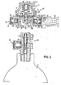
- the reducing valve 14 is best in Fi g . 2, it forms, together with a low-pressure safety valve 46 and a backflow safety valve 47, a structural unit which is referred to below as a “reducing valve unit” and is to be provided with the reference symbol 50 in its entirety.
- the reducing valve 14, the low-pressure safety valve 46 and the backflow safety valve 47 have a common valve housing 48, which consists of a cylindrical outer part 48 a of larger diameter and a cylindrical inner part 48 b of smaller diameter, which by an intermediate floor 49 are separated from each other.
- the intermediate floor 49 has a central opening 55 which is surrounded by an annular flange 56 which is located at a distance from the inner peripheral wall 57 of the inner housing part 48 b, which is the thickness of the wall 58 of the valve body 15 of the main valve 13 in the region of the outermost Stage 17 d corresponds to the valve bore 17.
- FIG. 1 it can be seen from Fig. 1 that when the reducing valve unit 50 is placed on the main valve 13, the annular wall 58 of the valve body 15 on the one hand and the upper part 31 of the valve seat screw 27 on the other hand in the annular space 59 between the outer wall of the inner housing part 4 8 b and engage the annular flange 56 or in the central opening 55 enclosed by this ring bottle 56.
- the valve seat screw 27 is sealed with an O-ring 60 against the ring flange 56 of the reducing valve housing 48 when the reducing valve unit 50 is plugged onto the main valve 13 .
- the low-pressure safety valve 46 and the backflow safety valve 47 have the same design, which is why only one of these two valves will be described below.
- the only difference is the force of the valve spring, which is much greater in the low-pressure safety valve 46 than in the backflow safety valve 47, since this latter valve only serves to prevent a backflow from the connecting line 52 into the interior of the valve arrangement 10 and, if necessary . also to prevent the inside of the high-pressure container 11 when the pressure in the high pressure vessel 1 1 and in the valve assembly 10 under the set low pressure drops.
- annular seat 61 is formed at the base of the connecting piece 51, which surrounds a radial bore 62, which opens into an axial bore 63, which through the intermediate floor 49 extends outwards into the low-pressure space 64 enclosed by the housing 48 stretches.
- a cup-shaped valve closure piece 66 In the radially extending, cylindrical interior 65 of the connecting piece 51 there is a cup-shaped valve closure piece 66, in the bottom 69 of which a sealing disk is embedded, which rests on the valve seat edge 61.
- valve closure piece 66 is axially displaceable in the interior 65 of the connection piece 51 and is loaded by a valve spring 69 which is supported at one end against the valve closure piece 66 and at the other end against a closure cap 70 which is screwed into the outer end of the connection piece 51 and has a gas outlet opening 71 through which the gas under low pressure can enter the extraction line 52.
- the low pressure safety valve 46 is also formed.
- a radial bore 62 ' leads into the valve chamber 65', which also carries an axial bore 63 '. communicates with the low pressure chamber 64.
- the reducing valve 14 will now be described in more detail below. For this purpose it should be pointed out in advance that of this reducing valve only the control part is present in the reducing valve unit 50, while the associated valve part is formed by the main valve 13 when the reducing valve unit 50 is plugged onto the main valve 13.
- the reducing valve 14 has a cap open on one side, which is screwed with an external thread 73 into the cylindrical wall of the outer housing part 48 a.
- a valve membrane 76 made of an elastomer is clamped between the free end edge 74 of the cap 72 and a shoulder 75 of the intermediate base 49 adjoining the peripheral wall of the outer housing part 48a.
- the spring plate hood 79 has an approximately frustoconical shape and a threaded bore open towards the diaphragm 76, into which the threaded shaft 80 of a valve tappet 81 is screwed, which rests with a shoulder 82 on the underside of the diaphragm 76 and penetrates it and the diaphragm plate 78 and thereby through it Membrane 76 clamped gas-tight between its shoulder 82 and the membrane plate 78.
- a compression spring 84 is supported on the outer edge of the spring plate hood 79, the other end of which rests on the outer edge of a cup-shaped spring plate 85.
- the pot bottom 86 of the spring plate 85 in turn is supported on the tip of an adjusting screw 86, which is screwed into a thread of the reducing valve housing cap 72 from the outside and is closed by a blind plug 87.
- the tension of the spring 84 can be changed with the adjusting screw 86 'and the desired low pressure can thereby be set.
- the main valve 13 also includes a protective cap, which is placed on the main valve 13 during the transport of the high-pressure container and engages in the annular groove 88 provided for this purpose, but in the drawing is not shown.
- the diaphragm 75 is pressed down by the compression spring 84 together with the valve tappet 81, so that the valve spindle 24 and you pushed the valve closure piece 22 down and the main valve is opened until the desired low pressure in the low pressure chamber 64 is restored.
- main valve 13 only opens when gas is withdrawn through the extraction line 52, but that the main valve 13 always remains closed when the consumer is switched off.
- the reducing valve will open the main valve 13 via the plunger 81.
- the backflow safety valve 47 is provided.
- the closure body 66 is pressed onto its seat by the valve spring 69 as soon as the set low pressure in the low pressure chamber 64 of the valve arrangement 10 is undershot.
- the low-pressure safety valve responds by the valve closure body lifting off its seat against the effect of the spring set to this safety pressure, and that Gas through holes 63 'and 62' and interior 65 ' of the low-pressure safety valve 46 can escape.
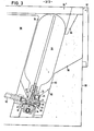
- Fig. 3 a particularly useful arrangement of the valve according to the invention is shown when it is used in the household for connection to a device.
- the arrangement shown here is intended, for example, for the operation of a bar, where a filling device for drinks is to be supplied with carbon dioxide gas, which is delivered in small gas bottles.
- a shaft slightly inclined to the vertical is provided in a table or cabinet 90 as a receiving device 31, the lower end 92 of which tapers in a funnel shape with inclined walls 93.
- the reducing valve unit 50 is arranged in a fixed position together with the removal line 52 leading to the device.
- the receiving shaft 91 is closed by the table top 94 ′, which forms a support for the high-pressure container 11 when the main valve 13 is inserted into the fixedly mounted reducing valve 50.
- the table top 94 ′ forms a support for the high-pressure container 11 when the main valve 13 is inserted into the fixedly mounted reducing valve 50.
- the table top 94 ′ forms a support for the high-pressure container 11 when the main valve 13 is inserted into the fixedly mounted reducing valve 50.
- the table top 94 ′ which forms a support for the high-pressure container 11 when the main valve 13 is inserted into the fixedly mounted reducing valve 50.
- the main valve 13 closes automatically because the valve spring 21 the valve closure piece 22 immediately presses on its seat 30 when the valve stem 24 is no longer loaded by the plunger 81.
- a new, filled gas bottle 11 can then be slid again through the filling opening 96 into the receiving device 91, the main valve 13 sliding along the inclined surfaces 93 of the funnel and being automatically introduced into the reducing valve in the reducing valve.
- the initially high resistance when opening the main valve 13 is easily overcome when the flap 97 is closed by the lever 98 connected to the flap 97 completely pushing the rear end of the bottle along the inclined surface formed by the table top 94 into the receiving device 91, whereby the high-pressure container 11 is also shifted so far in the axial direction that the parts 31 and 58 of the main valve 13 on the one hand and the parts 48 b and 56 of the reducing valve unit 50 on the other hand fully engage.
- the invention is not limited to the exemplary embodiments, but a number of changes and additions are possible without leaving the scope of the invention.
- a screw connection, a bayonet lock or the usual ball retaining ring can also be provided between the main valve and the reducing valve unit. It is also possible to manufacture the valve assembly without the safety valves if such facilities are otherwise available.
- the overhead arrangement of the high-pressure container and reducing valve can also be designed somewhat differently, without departing from the inventive concept.
Landscapes
- Physics & Mathematics (AREA)
- Fluid Mechanics (AREA)
- General Physics & Mathematics (AREA)
- Engineering & Computer Science (AREA)
- Automation & Control Theory (AREA)
- Filling Or Discharging Of Gas Storage Vessels (AREA)
- Container, Conveyance, Adherence, Positioning, Of Wafer (AREA)
- Feeding And Controlling Fuel (AREA)
- Magnetic Resonance Imaging Apparatus (AREA)
- Sampling And Sample Adjustment (AREA)
Priority Applications (1)
| Application Number | Priority Date | Filing Date | Title |
|---|---|---|---|
| AT81109234T ATE26757T1 (de) | 1980-12-23 | 1981-10-29 | Vorrichtung zur entnahme von gas. |
Applications Claiming Priority (2)
| Application Number | Priority Date | Filing Date | Title |
|---|---|---|---|
| DE3048732 | 1980-12-23 | ||
| DE19803048732 DE3048732A1 (de) | 1980-12-23 | 1980-12-23 | Ventilanordnung |
Publications (2)
| Publication Number | Publication Date |
|---|---|
| EP0054717A1 true EP0054717A1 (fr) | 1982-06-30 |
| EP0054717B1 EP0054717B1 (fr) | 1987-04-22 |
Family
ID=6120105
Family Applications (1)
| Application Number | Title | Priority Date | Filing Date |
|---|---|---|---|
| EP81109234A Expired EP0054717B1 (fr) | 1980-12-23 | 1981-10-29 | Dispositif pour prise de gaz |
Country Status (4)
| Country | Link |
|---|---|
| EP (1) | EP0054717B1 (fr) |
| AT (1) | ATE26757T1 (fr) |
| DE (2) | DE3048732A1 (fr) |
| GB (1) | GB2089954B (fr) |
Cited By (4)
| Publication number | Priority date | Publication date | Assignee | Title |
|---|---|---|---|---|
| DE3441348A1 (de) * | 1984-11-13 | 1986-05-22 | R. & G. Schmöle Metallwerke GmbH & Co KG, 5750 Menden | Ventilanordnung |
| WO2013076263A1 (fr) * | 2011-11-23 | 2013-05-30 | Micro Matic A/S | Système de distribution sous pression |
| CN108374916A (zh) * | 2017-12-06 | 2018-08-07 | 微马蒂奇股份公司 | 阀组件、气瓶、气体输送系统、气体消耗系统和饮料分配系统 |
| US11402069B2 (en) | 2017-12-06 | 2022-08-02 | Micro Matic A/S | Valve assembly |
Families Citing this family (5)
| Publication number | Priority date | Publication date | Assignee | Title |
|---|---|---|---|---|
| DE3430926A1 (de) * | 1984-08-22 | 1986-03-06 | Bosch-Siemens Hausgeräte GmbH, 7000 Stuttgart | Anordnung zum steckbaren anflanschen eines druckbehaelters an eine gasentnahmeeinrichtung |
| DE3430928A1 (de) * | 1984-08-22 | 1986-03-06 | Bosch Siemens Hausgeraete | Anordnung zum steckbaren anflanschen eines druckbehaelters an eine gasentnahmeeinrichtung |
| US5465750A (en) * | 1994-05-17 | 1995-11-14 | Standard Keil Industries, Inc. | Two-stage regulator |
| DE102004024597B4 (de) * | 2004-05-13 | 2006-02-09 | Msa Auer Gmbh | Kupplung für eine Druckgasflasche |
| DE102010052900B4 (de) * | 2010-12-01 | 2014-05-22 | Michael Dietl | Gasanlage, insbesondere für den Betrieb von Imbisswagen |
Citations (5)
| Publication number | Priority date | Publication date | Assignee | Title |
|---|---|---|---|---|
| DE763658C (de) * | 1941-07-29 | 1951-08-16 | Willy Rackow | Druckminderventil |
| FR1187594A (fr) * | 1957-01-03 | 1959-09-14 | Lancia Automobili | Régulateur de pression, en particulier pour compresseurs d'air alimentant un réservoir |
| FR1313173A (fr) * | 1961-11-13 | 1962-12-28 | Robinet détendeur pour gaz liquéfié | |
| FR1390963A (fr) * | 1963-10-26 | 1965-03-05 | Détendeur de sécurité pour bouteille de gaz sous pression et son application à un appareil vaporisateur | |
| US3547143A (en) * | 1968-11-29 | 1970-12-15 | Lif O Gen Inc | Single stage pressure regulator |
Family Cites Families (5)
| Publication number | Priority date | Publication date | Assignee | Title |
|---|---|---|---|---|
| DE688992C (de) * | 1938-04-24 | 1940-11-02 | Willy Rackow | Stahlflasche mit Druckregler fuer unter Druck stehende verfluessigte Gase |
| DE1024803B (de) * | 1955-07-07 | 1958-02-20 | Kidde Walter Co Ltd | Geraet zur Entnahme von Gas aus einem Druckgasbehaelter, insbesondere fuer Sauerstoffatemgeraete |
| DE1122341B (de) * | 1956-01-12 | 1962-01-18 | Kidde Walter Co Ltd | Reduzierventil mit einem mit dem Stoessel des Verschlussstueckes zusammenwirkenden, auf- und abschraubbaren Stellglied |
| DE1130659B (de) * | 1958-02-25 | 1962-05-30 | Kosangas As | Zwei-Stufen-Reduzierventil mit voneinander unabhaengig wirkenden Stufen |
| DE1955150A1 (de) * | 1969-11-03 | 1971-05-13 | Barrel Fresh Service Ag | Druckregel- und Druckmessgeraet |
-
1980
- 1980-12-23 DE DE19803048732 patent/DE3048732A1/de not_active Withdrawn
-
1981
- 1981-04-09 GB GB8111196A patent/GB2089954B/en not_active Expired
- 1981-10-29 AT AT81109234T patent/ATE26757T1/de not_active IP Right Cessation
- 1981-10-29 DE DE8181109234T patent/DE3176132D1/de not_active Expired
- 1981-10-29 EP EP81109234A patent/EP0054717B1/fr not_active Expired
Patent Citations (5)
| Publication number | Priority date | Publication date | Assignee | Title |
|---|---|---|---|---|
| DE763658C (de) * | 1941-07-29 | 1951-08-16 | Willy Rackow | Druckminderventil |
| FR1187594A (fr) * | 1957-01-03 | 1959-09-14 | Lancia Automobili | Régulateur de pression, en particulier pour compresseurs d'air alimentant un réservoir |
| FR1313173A (fr) * | 1961-11-13 | 1962-12-28 | Robinet détendeur pour gaz liquéfié | |
| FR1390963A (fr) * | 1963-10-26 | 1965-03-05 | Détendeur de sécurité pour bouteille de gaz sous pression et son application à un appareil vaporisateur | |
| US3547143A (en) * | 1968-11-29 | 1970-12-15 | Lif O Gen Inc | Single stage pressure regulator |
Cited By (6)
| Publication number | Priority date | Publication date | Assignee | Title |
|---|---|---|---|---|
| DE3441348A1 (de) * | 1984-11-13 | 1986-05-22 | R. & G. Schmöle Metallwerke GmbH & Co KG, 5750 Menden | Ventilanordnung |
| US4660601A (en) * | 1984-11-13 | 1987-04-28 | R. & G. Schmoele Metallwerke Gmbh & Co. Kg | Valve arrangement |
| WO2013076263A1 (fr) * | 2011-11-23 | 2013-05-30 | Micro Matic A/S | Système de distribution sous pression |
| US9360162B2 (en) | 2011-11-23 | 2016-06-07 | Micro Matic A/S | Pressure delivery system |
| CN108374916A (zh) * | 2017-12-06 | 2018-08-07 | 微马蒂奇股份公司 | 阀组件、气瓶、气体输送系统、气体消耗系统和饮料分配系统 |
| US11402069B2 (en) | 2017-12-06 | 2022-08-02 | Micro Matic A/S | Valve assembly |
Also Published As
| Publication number | Publication date |
|---|---|
| ATE26757T1 (de) | 1987-05-15 |
| DE3048732A1 (de) | 1982-07-15 |
| GB2089954B (en) | 1984-05-16 |
| EP0054717B1 (fr) | 1987-04-22 |
| DE3176132D1 (en) | 1987-05-27 |
| GB2089954A (en) | 1982-06-30 |
Similar Documents
| Publication | Publication Date | Title |
|---|---|---|
| DE69832211T3 (de) | Getränkespender | |
| DE60005457T2 (de) | Abgabevorrichtung für unter druck stehende flüssigkeit mit separater druckgasquelle | |
| DE3888773T2 (de) | Druckgefäss. | |
| EP1204555B1 (fr) | Dispositif de conservation d'une bouteille pour boissons ouverte | |
| EP0163007B1 (fr) | Soupape de distribution et de sûreté pour un siphon pour crème, ou similaire | |
| DE2362422A1 (de) | Selbsttaetig absperrende zapfpistole | |
| DE69304658T2 (de) | Das Nachfüllen verhinderndes Ventil für nicht nachfüllbare Behälter | |
| DE2641538A1 (de) | Fuellventil zur fuellung von flaschen mit unter druck stehenden getraenken | |
| EP0270878A1 (fr) | Dispositif pour soutirer de la bière à partir de récipients, notamment de tonnelets | |
| EP0681555A1 (fr) | Distributeur pour tonneaux. | |
| DE3048732A1 (de) | Ventilanordnung | |
| DE2454888A1 (de) | Flaschenfuellmaschine | |
| EP1131574B1 (fr) | Dispositif d'arret pour systeme de remplissage d'un recipient a pression | |
| EP2295372A1 (fr) | Chapiteau destiné à tirer par pression pour conteneur à bière et procédé de fonctionnement de celui-ci | |
| DE2123865A1 (de) | Füllelement | |
| DE2300426A1 (de) | Druckregelventil | |
| DE2521099C3 (de) | Druckversorgungsteil für aus druckdichten Behältern zu entnehmende Flüssigkeiten | |
| EP0140106A2 (fr) | Soupape de soutirage pour prélever des gaz combustibles condensés d'un réservoir de stockage | |
| DE2939288A1 (de) | Schnapphahn fuer fluide | |
| DE2750413A1 (de) | Ventil fuer gasbehaelter | |
| DE8034293U1 (de) | Vorrichtung zur entnahme von gas | |
| DD264414A1 (de) | Vorrichtung zur steuerung von fuellventilen | |
| EP2339422B1 (fr) | Unité de réglage de pression | |
| DE20215897U1 (de) | Vorrichtung zum Filtern von Flüssigkeit und zum Lösen eines Gases in einer Flüssigkeit | |
| DE1940409A1 (de) | Reduzierventil |
Legal Events
| Date | Code | Title | Description |
|---|---|---|---|
| PUAI | Public reference made under article 153(3) epc to a published international application that has entered the european phase |
Free format text: ORIGINAL CODE: 0009012 |
|
| AK | Designated contracting states |
Designated state(s): AT BE CH DE FR GB IT LU NL SE |
|
| 17P | Request for examination filed |
Effective date: 19821001 |
|
| ITF | It: translation for a ep patent filed | ||
| GRAA | (expected) grant |
Free format text: ORIGINAL CODE: 0009210 |
|
| AK | Designated contracting states |
Kind code of ref document: B1 Designated state(s): AT BE CH DE FR IT LI LU NL SE |
|
| REF | Corresponds to: |
Ref document number: 26757 Country of ref document: AT Date of ref document: 19870515 Kind code of ref document: T |
|
| REF | Corresponds to: |
Ref document number: 3176132 Country of ref document: DE Date of ref document: 19870527 |
|
| ET | Fr: translation filed | ||
| PG25 | Lapsed in a contracting state [announced via postgrant information from national office to epo] |
Ref country code: LU Free format text: LAPSE BECAUSE OF NON-PAYMENT OF DUE FEES Effective date: 19871031 |
|
| PGFP | Annual fee paid to national office [announced via postgrant information from national office to epo] |
Ref country code: NL Payment date: 19871031 Year of fee payment: 7 |
|
| PLBE | No opposition filed within time limit |
Free format text: ORIGINAL CODE: 0009261 |
|
| STAA | Information on the status of an ep patent application or granted ep patent |
Free format text: STATUS: NO OPPOSITION FILED WITHIN TIME LIMIT |
|
| 26N | No opposition filed | ||
| PG25 | Lapsed in a contracting state [announced via postgrant information from national office to epo] |
Ref country code: AT Effective date: 19881029 |
|
| PG25 | Lapsed in a contracting state [announced via postgrant information from national office to epo] |
Ref country code: SE Effective date: 19881030 |
|
| PG25 | Lapsed in a contracting state [announced via postgrant information from national office to epo] |
Ref country code: LI Effective date: 19881031 Ref country code: CH Effective date: 19881031 Ref country code: BE Effective date: 19881031 |
|
| BERE | Be: lapsed |
Owner name: CARL ESSER DRUCKGASARMATUREN Effective date: 19881031 |
|
| PG25 | Lapsed in a contracting state [announced via postgrant information from national office to epo] |
Ref country code: NL Effective date: 19890501 |
|
| NLV4 | Nl: lapsed or anulled due to non-payment of the annual fee | ||
| PG25 | Lapsed in a contracting state [announced via postgrant information from national office to epo] |
Ref country code: FR Free format text: LAPSE BECAUSE OF NON-PAYMENT OF DUE FEES Effective date: 19890630 |
|
| REG | Reference to a national code |
Ref country code: CH Ref legal event code: PL |
|
| PG25 | Lapsed in a contracting state [announced via postgrant information from national office to epo] |
Ref country code: DE Effective date: 19890701 |
|
| REG | Reference to a national code |
Ref country code: FR Ref legal event code: ST |
|
| EUG | Se: european patent has lapsed |
Ref document number: 81109234.5 Effective date: 19890614 |