EP0054727A2 - Commutateur et méthode pour le fabriquer - Google Patents
Commutateur et méthode pour le fabriquer Download PDFInfo
- Publication number
- EP0054727A2 EP0054727A2 EP81109358A EP81109358A EP0054727A2 EP 0054727 A2 EP0054727 A2 EP 0054727A2 EP 81109358 A EP81109358 A EP 81109358A EP 81109358 A EP81109358 A EP 81109358A EP 0054727 A2 EP0054727 A2 EP 0054727A2
- Authority
- EP
- European Patent Office
- Prior art keywords
- hub
- segment assembly
- commutator
- segment
- armature shaft
- Prior art date
- Legal status (The legal status is an assumption and is not a legal conclusion. Google has not performed a legal analysis and makes no representation as to the accuracy of the status listed.)
- Granted
Links
Images
Classifications
-
- H—ELECTRICITY
- H01—ELECTRIC ELEMENTS
- H01R—ELECTRICALLY-CONDUCTIVE CONNECTIONS; STRUCTURAL ASSOCIATIONS OF A PLURALITY OF MUTUALLY-INSULATED ELECTRICAL CONNECTING ELEMENTS; COUPLING DEVICES; CURRENT COLLECTORS
- H01R39/00—Rotary current collectors, distributors or interrupters
- H01R39/02—Details for dynamo electric machines
- H01R39/04—Commutators
-
- H—ELECTRICITY
- H01—ELECTRIC ELEMENTS
- H01R—ELECTRICALLY-CONDUCTIVE CONNECTIONS; STRUCTURAL ASSOCIATIONS OF A PLURALITY OF MUTUALLY-INSULATED ELECTRICAL CONNECTING ELEMENTS; COUPLING DEVICES; CURRENT COLLECTORS
- H01R43/00—Apparatus or processes specially adapted for manufacturing, assembling, maintaining, or repairing of line connectors or current collectors or for joining electric conductors
- H01R43/06—Manufacture of commutators
-
- Y—GENERAL TAGGING OF NEW TECHNOLOGICAL DEVELOPMENTS; GENERAL TAGGING OF CROSS-SECTIONAL TECHNOLOGIES SPANNING OVER SEVERAL SECTIONS OF THE IPC; TECHNICAL SUBJECTS COVERED BY FORMER USPC CROSS-REFERENCE ART COLLECTIONS [XRACs] AND DIGESTS
- Y10—TECHNICAL SUBJECTS COVERED BY FORMER USPC
- Y10T—TECHNICAL SUBJECTS COVERED BY FORMER US CLASSIFICATION
- Y10T29/00—Metal working
- Y10T29/49—Method of mechanical manufacture
- Y10T29/49002—Electrical device making
- Y10T29/49009—Dynamoelectric machine
- Y10T29/49011—Commutator or slip ring assembly
Definitions
- the invention relates to a commutator with a reinforced segment assembly, which is arranged with the interposition of insulation on a hub or an armature shaft, and to a method for producing such a commutator.
- the known commutators with an armored segmented ribbon are those of the arch pressure type. With them, so-called segment jumps can be avoided even at high centrifugal stresses, as occurs at high speeds, because the arch pressure can be chosen so large that the surface pressure generated by the arch pressure between the segments and the insulating lamellae is sufficient for all operating conditions Reliably prevent emigration of the segments.
- commutators are often not only exposed to high centrifugal forces, but also to high thermal loads.
- the deformation of the brushes due to the heating of the commutator tread which is a reversible deformation in shape. short and / or long-wave deviations from the cylinder shape then limits the maximum speed for which the commutator can still be used.
- the invention has for its object to provide a commutator of the type mentioned, which has no or at least a significantly lower thermal deformation than the known commutators. This object is achieved with the features of claim 1.
- the solution according to the invention is based on the consideration that, in the case of commutators of the arch pressure type, the radial forces emanating from the armored segment assembly and resulting from the arch pressure are effective due to the inevitable material inhomogeneity and dimensional asymmetry of the segment association over the circumference thereof in different size distributions. They bring about an individual balance adjustment for each commutator with appropriate rejection of the segment association already during its manufacture.
- the deformation caused by the warping of the segment assembly is eliminated by overturning it on the finished commutator, but the different size distribution of the radial forces over the circumference of the segment assembly is retained.
- a renewed deformation of the segment assembly and thus the brush tread is therefore preprogrammed and will occur due to the weak reaction forces of the reinforcement elements specially designed to absorb centrifugal forces and to maintain sufficient arch tension, but only to a small extent rigid under any kind of operational stress.
- the steady heating of the commutator during operation to its operating temperature results in an increasing degree of asymmetry of the segment assembly, which results from the inhomogeneity of the segment assembly, in particular the insulating lamellae, which results from the inhomogeneity of the segment assembly , due to the increase in vault pressure due to heat and the rise in pressure and heat as a result of the superposing forces, a further increase in the size differences of the radial forces effective over the circumference of the segmental association.
- the relatively soft, orthotropic segment structure the reduction or build-up of the radial forces acting over the circumference of the segment structure occurs over relatively large distances.
- the support forces introduced are chosen to be substantially higher than any of them which is reduced by thermal and centrifugal force loads on the commutator in later operation.
- the segment assembly is always oriented via an intimate frictional connection to the commutator hub and a correspondingly high reaction of the supporting forces when deformation occurs is guaranteed in each of the operating states that occur later.
- a relatively low arch pressure is sufficient to prevent individual segments from migrating on the still cold, but subject to centrifugal force.
- a significant reduction in the arch pressure results in the same reinforcement compared to a commutator of the arch pressure type in that the armored segment assembly is expanded to such an extent in the course of the manufacture of the commutator that a predominant stress component of the armoring, the hub and / or shaft shaft coupled positively to it and radially prestresses the insulation between it and the segmental structure.
- the area of the segments and insulating lamellae under arching stress is additionally reduced to a dimension that is still required dynamically and is still necessary in terms of production technology.
- This reduction in the area under vaulting which can be achieved by recesses and / or deposits of the segments and / or the insulating lamellae, further reduces the radial forces caused by heating and caused by inhomogeneity and dimensional asymmetry, since the heating-related expansion of the Segment association or increase in vault tension is significantly reduced because of the considerable reduction in the areas generating the compressive forces in the circumferential direction. Due to the substantial reduction in vault pressure in the greatly reduced vault pressure area, the forces acting under heat in the segment assembly are greatly reduced and, as a result of the support effect emanating from the hub, the segment ends receiving the reinforcements are greatly relieved.
- the invention is also based on the object of providing a method for producing the commutator according to the invention which is as simple as possible to carry out. This object is achieved with the features of claim 10. Advantageous others. Refinements of this method are the subject of claims 11 to 18.
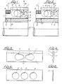
- segments 1 and insulating lamellae 2 In each case, one of these plate-shaped insulating lamellae 2, consisting of Mikanit_, lies between two segments 1 made of copper.
- the segments 1, whose cross-sectional profile is shown in FIG. 4, have a shoulder 1 'on both side surfaces along their outer edge. These two deposits 1 'reduce the thickness of the segment in the outer edge zone to such an extent that there is no longer any noteworthy arch pressure on the finished commutator. Furthermore, the segments 1 are provided with two openings 3, which are arranged symmetrically and in the longitudinal direction of the commutator at a distance from one another, which are punched out of the segment and protrude from a slot differentiate in shape that they have different sized radii at both ends. The smaller radius is provided at the end adjacent to the other opening. The web 4 present between the two openings 3 is located centrally between the ends of the segment.
- the insulating plates 2 each have three circular punchings 5 of the same size, which are arranged at equal distances from one another in the longitudinal direction of the commutator.
- the central punch 5 lies in the middle between the two ends of the insulating lamella. It is therefore aligned with the web 4. Since the centers of curvature of the openings 3 and the centers of the punched-out areas 5 have the same distances from the inner surface of the segment assembly, the partial coverage shown in FIGS. 1 and 2 results. In the areas of the deposits 1 ', the surface pressure between the segments 1 and the insulating strips 2 is very low. No arch pressure is transmitted in the areas covered by the openings 3 and punched-out areas 5.
- a vault pressure can therefore only be generated practically in the surface area lying between the openings 3 and the punched-out sections 5 on the one hand and the inner lateral surface of the segment assembly on the other hand and the two offset end zones, each of which has an insulated reinforcement ring 6 on the outside.
- the step for receiving the reinforcement ring 6 is turned out on the composite segment assembly in order to ensure uniform contact with all segments.
- the reinforced segmental assembly sits concentrically on a metallic hub 8 with the interposition of insulation 7, which in turn sits on a shaft 9.
- the insulation 7, the hub 8 and the shaft 9 are prestressed in the radial direction, the latter two parts forming an extremely rigid and largely material-homogeneous and dimensionally symmetrical body, of which in close proximity ideally run out equally large, radially symmetrical supporting forces S.
- the hub 8 and the shaft 9 were not preloaded in the radial direction, the armored segment assembly, as in the known commutators of the arch pressure type, would only sit positively on the hub 8, then the clamping force F generated by the reinforcement rings 6 would have a very high arch tension and therefore generate a relatively large resulting radial force G R.
- the radial force G of the vault tension is reduced to the much smaller value G.
- the centrifugal force Z claims the lamellar structure in the same direction as the radial force G ' r generated by the arch tension.
- the preloaded hub 8 and the preloaded shaft 9 have a very hard spring characteristic, the centrifugal force Z without a noteworthy radial movement of the segment by a corresponding reduction in the supporting forces S 'or their radial components S r '.
- the change in vault tension in the reduced zones that still transmit the vault pressure is therefore slight under the influence of centrifugal force. Accordingly, the difference in size of the resulting radial forces G with the stationary r and G 'with the rotating commutator is small.
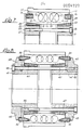
- the segment assembly is composed of alternating segments 11 and insulating lamellae 12.
- the segments 11 each have a shoulder 11 'along their outer edge zone adjacent to the running surface for the brushes. Furthermore, they are provided with openings 13, which are offset from punched holes 15 of the insulating lamellae 12 such that they are aligned with the webs 14 between the punched holes 15.
- the vault pressure zone is essentially limited to the area between the openings and punched-out areas and the inner surface of the segment assembly and the two end zones, which lie within two reinforcing rings 16, which are made of Steel and lie in the end-face ring grooves with the interposition of insulation.
- the inner lateral surface of the segment assembly forms an inner cone that widens outward.
- the two support rings 20 lie on the cylindrical outer circumferential surface of a steel half-hub 21 and 21 ', the inner circumferential surfaces of which form a bore for receiving a shaft.
- a potting compound 24 fills the gaps between the reinforcing rings 16 and the segments 11 and the insulating lamella 12 on both ends of the commutator and covers the outwardly facing end faces of the reinforcing rings 16, the supporting rings 20 and the end sections of the segments 11 and insulating lamella 12 lying between them towards the outside, in the exemplary embodiment the outward-facing side of the casting compound 24 being aligned with the adjacent end face of the half-hub.
- the support rings 20 can be omitted, for example if the hub halves 21 and 21 'are relatively thin-walled, for example due to a large bore, if the hub halves bear with the outer circumferential surface, which is designed as an outer cone, on the corresponding inner cone of the segment assembly, and by means of insulation the clamping screws 23 are clamped together.
- This commutator is manufactured in such a way that the armored segment assembly is heated to a temperature which is somewhat higher than the operating temperature of the commutator.
- the two half hubs 21 and 21 ' are preferably pressed in during this heating together with the support rings 20 arranged on them.
- the segment association is expanded until it comes into contact with a stop ring which receives the segment assembly during this manufacturing process.
- the support rings 20 are preferably shrunk onto the half-hubs 21 and 21 'in order to avoid any air between them, their insulation and the half-hub.
- the half hubs and the support rings are held under the press-in pressure until the segment assembly has cooled again.
- the expansion is chosen so that the required radial preload of the half-hubs 21 and 21 'and the support rings 20 is achieved after the segment assembly has cooled.
- the two half hubs are screwed together using the clamping screws 23.
- the two end faces of the segment assembly and the support rings 20 are potted using the sealing compound 2d.
- the structure of the segment structure of the exemplary embodiment shown in FIG. 8 differs from the segment structure of the exemplary embodiment according to FIG. 7 only in that the two reinforcement rings 36 are designed as pressure rings, each with an inner cone that bears against an outer cone that the inner flank of forms the armoring ring partially receiving the front annular groove of the segmental association.
- the reinforcement rings 36 made of steel are provided with an insulation that envelops them.
- a clamping ring 45 is arranged so as to be longitudinally displaceable on the two half-hubs 41 and 41 '.
- the two insulated support rings 40 are designed like the support rings 20 and are preferably shrunk onto the half-hub carrying them in order to remove any air between them, their insulation and the half-hub to avoid. You are also engaged by an annular flange of the half-hub to be tightened to the same extent when clamping the half-hubs.
- Each of the two clamping rings 45 has, following a cylindrical surface on which the outer, cylindrical part of the inner circumferential surface of the reinforcing ring 36 rests, a radially outwardly projecting ring flange which rests on the outwardly facing end face of the clamping ring.
- a plurality of threaded bores 42 which are evenly distributed on the circumference and parallel to the longitudinal axis of the commutator, in one clamping ring 45 and through holes aligned with them in the two half-hubs 41 and 41 'and in the other clamping ring 45 each serve to accommodate a clamping screw 43 with which the two clamping rings 45 and thus the reinforcement rings 36 are clamped together.
- the two half-hubs 41 and 41 ' are also alternately provided with threaded holes 46, which are arranged offset to the through holes for the clamping screws 43, also parallel to the longitudinal axis of the commutator and evenly distributed on the circumference, with which the respectively associated through holes in the other half hub 41' or 41 and the tension rings 45 carried by them are aligned.
- these holes are clamping screws 47, by means of which on the one hand the semi-hub 41 via carried by it, resting with its outer cone on the inner cone of the segment association support ring 40 with the armouring - ring 36 supporting the clamping ring 45 and on the other hand, the semi-hub 41 'via the supporting ring 40 can be clamped together with the clamping ring 45 carrying the opposite reinforcement ring 36.
- the clamping screws 47, which clamp the half hub 41 'together with the clamping ring 45, which is displaceably arranged on the opposite half hub ' 41, are not shown in FIG. 8.
- This commutator is manufactured in such a way that a shrinking process, e.g. by means of a conical bushing, via which the segment assembly is pressed into a thick-walled, cylindrical pressure bushing, the segment assembly is given a vault tension. Then, by tightening the tensioning screws 43, the two tensioning rings 45 and together with these the two reinforcement rings 36 are put together. clamps and the armored segment assembly is pressed out of the pressure bush. The two tensioned reinforcement rings now take over the maintenance of the arch tension in the segment association. The segment assembly is then heated to a temperature which is above the later operating temperature, and, preferably in the course of this heating, the half-hubs 41 and 41 'and the support rings 40 carried by them are pressed in with axial pressure.
- a shrinking process e.g. by means of a conical bushing, via which the segment assembly is pressed into a thick-walled, cylindrical pressure bushing, the segment assembly is given a vault tension. Then, by tightening the tension
- segment assembly is widened, as in the exemplary embodiment according to FIG. 7, until it lies against a stop ring or a stop bush which receives the segment assembly during this manufacturing process.
- the two half-hubs are kept under this axial pressure until they cool down. Then the clamping screws 47 are tightened. Due to the widening of the segment assembly and its subsequent shrinking when cooling, the two half-hubs 41 and 41 'and the support rings 40 receive a radial preload which is reduced during operation of the commutator, but is not completely removed.
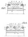
- the armored segment assembly of the embodiment according to FIG. 9 differs from that of the embodiment according to FIG. 7 only in that its inner jacket ⁇ surface is also cylindrical in the end portions.
- Deposits 51 'of the segments 51 and openings 53 of the same and punched-out sections 55 of the insulating lamellae 52 therefore also limit the arching tension here essentially to the area between the openings and the punched-out section on the one hand and the inner lateral surface / area and the two end zones lying within the reinforcing rings 56.
- a molding material 57 which isolates the segment assembly from the hub and transmits the radial forces.
- the press material 57 which is a mass customary in commutator construction for press commutators, also covers the end faces of the reinforcement rings 56 and the end zones of the lamellar assembly encompassed and fills the ring grooves receiving the reinforcement rings, insofar as the reinforcement rings do not .
- To produce such a commutator of the reinforced segment dressing is introduced by heating to a required for the processing of the Preßstoffes 5 7 Preßtechnik Weg Kunststofftemperatur, which may be, depending on the pressed material to over 200 °, and by the between the inner lateral surface of the segment, the association and the hub 5 8 under pressure Pressed material 5 7 expanded until the outer lateral surface abuts on a press bushing which accommodates the segment assembly.
- the inner diameter of this press bush and thus the degree of expansion of the segment assembly is selected so that when the segment assembly cools and the shrinkage associated therewith, the hub 5 8 and the press material 57 lying between it and the segment assembly receive the required radial prestress.
- this commutator represents a particularly economical embodiment of the commutator according to the invention.
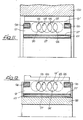
- the exemplary embodiment shown in FIG. 10, like the exemplary embodiment according to FIG. 9, is a ring-armored press commutator. However, it does not differ from the latter only in that, in addition to the / both ends of the segment assembly, a third reinforcement ring 76 'is arranged at half the length, which is particularly advantageous with a longer commutator length. A difference also lies in the fact that the reinforcement rings 76 and 76 'are insulated from the segments 7 1 by a press material 77 which, when pressed, fills the space between the reinforcement rings and the grooves receiving them.
- the third reinforcing ring 76 ' also requires a slightly different configuration of the openings 7 and 3 of the segments 75 of the punch-outs Isolierlamellen lying between them, as Fig. 1 shows 0. Thanks to these recesses and openings as well as the stepped portions 71 'of the segments 71 , the arch pressure zone, that is to say the surface area of the segments and insulating lamellas in which the arch tension is effective, is also greatly reduced in this exemplary embodiment.
- a further difference between the exemplary embodiment according to FIG. 10 and that according to FIG. 9 is that 78 that the bright steel hub / has a conical outer surface. Instead of this one-piece hub or a shaft with an outer cone, two half-hubs with an outer cone could also be used.
- the commutator according to FIG. 10 is produced in such a way that, like a press commutator, the prestressed segment assembly, in which the hub 78 has not yet been inserted, is pressed with press material 77, which completely embeds the reinforcement rings 76 and 76 '.
- the molding material 77 completely covers the two outer reinforcement rings 76 and the end sections of the segments 71 lying inside them, and in the exemplary embodiment is flush with the hub end face.
- Completely with The ring slot is also filled with molding material, via which the ring groove containing the third reinforcement ring 76 'is connected to the inner circumferential surface of the segment assembly.
- the insulating layer formed by the molding material 77 on the inner surface of the segment assembly has a conical inner surface corresponding to the outer cone of the hub 78.
- the commutator according to FIG. 10 has the advantage that completely punched-out segments and insulating lamellae can be used, that is to say no machining of the segment assembly - for the production of the seats required for the reinforcement rings and no insulation of the reinforcement rings is necessary.
- the exemplary embodiment shown in FIGS. 11 and 12 differs from the previously described exemplary embodiments in particular in that already in the course of the reduction in diameter required for the arch pressure build-up of the segment assembly, for example, composed of segments 91 with openings 93 as well as recesses 91 'and insulating strips 92 with punched-outs 95 by means of a conical socket over which the segmental association is pressed into a pressure bushing 100, a relatively thin-walled, insulated hub sleeve 101 is shrunk into the receiving bore of the segment assembly and non-positively connected to it.
- the amount of compression of the hub sleeve 101 can be reduced by reducing the diameter by specifying a difference between the diameter of the receiving bore of the segmental structure and the outer diameter the insulated hub sleeve 101 can be determined. After it has been pressed into the pressure bushing 100, an annular groove is screwed in at both ends for receiving an insulated reinforcing ring 96 at each end.
- the compression of the hub is chosen so high that after the reinforcement rings 96 have been shrunk onto the segment ends exposed by the annular groove and the armored segment assembly has been removed from the pressure bushing 100, the segment assembly to a large extent with a substantial reduction in the arch tension and increasing tension build-up in the Reinforcing rings 96 expands due to the high support forces of the compressed hub sleeve 101.
- the segmental association radially prestressed by the hub sleeve 101 is then heated. A hub 98 is pressed in.
- the hub sleeve 101 which is shrunk into the segmental structure as a pressure sleeve, could also have a slightly conical bore.
- the hub or armature shaft provided with a corresponding outer cone could then be pressed in as the segment assembly heats up.
- a conical hub has the advantage that, since it has already been introduced and pressurized in the course of the heating of the segment assembly in the receiving bore, it supports the ends of the segments 91 carrying the reinforcing rings 96.
- the coefficient of expansion of the segment assembly is namely greater than that of the reinforcing rings 96 made of steel. Therefore the segments 91 experience increasing bending stress at their ends when heated.
- the hub sleeve is wrapped in a thin insulating tape that surrounds it like a coil and forms double insulation 97 of the segment assembly with respect to the armature shaft.
- Good heat dissipation to the armature shaft is ensured by the two very thin insulating layers between the segment assembly and the hub 98 or armature shaft.
- the resulting low heat gradient between the segment assembly and the hub and / or the armature shaft contributes to the fact that the reduction of supporting forces of the hub remains extremely low. This effect of good heat dissipation from the commutator to the armature shaft naturally also applies to the other exemplary embodiments.
- the insulation can of course also be formed by such a winding in other exemplary embodiments.
Landscapes
- Motor Or Generator Current Collectors (AREA)
- Manufacturing Of Electrical Connectors (AREA)
- Manufacture Of Motors, Generators (AREA)
Applications Claiming Priority (2)
| Application Number | Priority Date | Filing Date | Title |
|---|---|---|---|
| DE3048470 | 1980-12-22 | ||
| DE3048470A DE3048470C2 (de) | 1980-12-22 | 1980-12-22 | Kommutator und Verfahren zu seiner Herstellung |
Publications (3)
| Publication Number | Publication Date |
|---|---|
| EP0054727A2 true EP0054727A2 (fr) | 1982-06-30 |
| EP0054727A3 EP0054727A3 (en) | 1983-03-30 |
| EP0054727B1 EP0054727B1 (fr) | 1987-02-04 |
Family
ID=6119946
Family Applications (1)
| Application Number | Title | Priority Date | Filing Date |
|---|---|---|---|
| EP81109358A Expired EP0054727B1 (fr) | 1980-12-22 | 1981-10-30 | Commutateur et méthode pour le fabriquer |
Country Status (5)
| Country | Link |
|---|---|
| US (1) | US4562369A (fr) |
| EP (1) | EP0054727B1 (fr) |
| JP (1) | JPS57170047A (fr) |
| DE (1) | DE3048470C2 (fr) |
| DK (1) | DK172454B1 (fr) |
Cited By (1)
| Publication number | Priority date | Publication date | Assignee | Title |
|---|---|---|---|---|
| EP0350855A3 (en) * | 1988-07-14 | 1990-09-19 | Kautt & Bux Kg | Commutator and process for manufacturing same |
Families Citing this family (13)
| Publication number | Priority date | Publication date | Assignee | Title |
|---|---|---|---|---|
| DE3245699A1 (de) * | 1982-12-10 | 1984-06-14 | Kautt & Bux Kg, 7000 Stuttgart | Kommutator und verfahren zu seiner herstellung |
| DE3714098A1 (de) * | 1987-04-28 | 1988-11-10 | Kautt & Bux Kg | Kommutator fuer maschinen kleiner bis mittlerer groesse und verfahren zu seiner herstellung |
| DE8708940U1 (de) * | 1987-06-27 | 1988-05-26 | Kautt & Bux Kg, 7000 Stuttgart | Kommutator für elektrische Maschinen |
| DE3823844A1 (de) * | 1988-07-14 | 1990-01-18 | Kautt & Bux Kg | Kommutator fuer elektrische maschinen und verfahren zu seiner herstellung |
| JPH02101947A (ja) * | 1988-10-07 | 1990-04-13 | Asmo Co Ltd | 整流子及びその製造方法 |
| US5171010A (en) * | 1992-01-08 | 1992-12-15 | Lanoue Todd W | Golf ball teeing apparatus |
| DE4201593C2 (de) * | 1992-01-22 | 1999-06-10 | Bosch Gmbh Robert | Kommutator für elektrische Maschinen und Verfahren zu seiner Herstellung |
| DE9321246U1 (de) * | 1993-02-01 | 1996-09-26 | Friedrich Nettelhoff KG Spezialfabrik für Kleinkollektoren, 58708 Menden | Kollektor und Armierungsring hierzu |
| WO1995022184A1 (fr) * | 1994-02-10 | 1995-08-17 | Comtrade Handelsgesellschaft Mbh | Bague d'armature pour corps de rotation et son procede de fabrication |
| WO1998026478A1 (fr) * | 1996-12-12 | 1998-06-18 | Comtrade Handelsgesellshaft Mbh | Commutateur muni d'une bague d'armature |
| US6242839B1 (en) | 2000-03-01 | 2001-06-05 | Kirkwood Industries, Inc. | Commutator and method for manufacturing |
| US6666349B1 (en) | 2000-12-18 | 2003-12-23 | Norman W. Gavin | Septic system tank |
| DE10319460A1 (de) * | 2003-04-29 | 2004-11-18 | Robert Bosch Gmbh | Elektrohandwerkzeugmaschine mit elektromotorischem Antrieb |
Family Cites Families (21)
| Publication number | Priority date | Publication date | Assignee | Title |
|---|---|---|---|---|
| DE533323C (de) * | 1931-09-12 | Aeg | Stromwendersegment mit Aussparung im Befestigungsteil | |
| GB814679A (en) * | 1956-10-09 | 1959-06-10 | British Thomson Houston Co Ltd | Improvements in electrical commutators |
| DE313299C (fr) * | ||||
| DE287378C (fr) * | 1912-03-02 | |||
| US2221571A (en) * | 1938-04-14 | 1940-11-12 | Westinghouse Electric & Mfg Co | Commutator and clamping structure therefor |
| DE852412C (de) * | 1941-06-17 | 1952-10-13 | Brown Ag | Kollektor fuer elektrische Maschinen |
| DE875232C (de) * | 1942-02-05 | 1953-04-30 | Siemens Ag | Kommutator fuer elektrische Maschinen oder Apparate, insbesondere Kohlekommutator |
| DE891415C (de) * | 1942-03-05 | 1953-09-28 | Siemens Ag | Kollektor |
| US2426042A (en) * | 1944-07-20 | 1947-08-19 | Westinghouse Electric Corp | Commutator |
| US2795841A (en) * | 1952-10-27 | 1957-06-18 | Lincoln Electric Co | Method of manufacturing commutators |
| GB962317A (en) * | 1960-07-26 | 1964-07-01 | Bushing Company Ltd | Improvements relating to commutators for dynamo-electric machines |
| DE1275193B (de) * | 1963-10-15 | 1968-08-14 | Siemens Ag | Verfahren zur Herstellung eines Kommutators fuer elektrische Maschinen |
| FR1451412A (fr) * | 1965-07-08 | 1966-01-07 | Perfectionnement aux collecteurs d'appareils électriques tournants | |
| CH466418A (de) * | 1967-11-17 | 1968-12-15 | Bbc Brown Boveri & Cie | Auf einer Welle elektrisch isoliert aufgeschrumpfter Schleifring oder Kollektor |
| CH464334A (de) * | 1968-02-21 | 1968-10-31 | Siemens Ag | Kommutator für elektrische Maschinen und Verfahren zum Herstellen eines solchen |
| CH506897A (de) * | 1970-04-20 | 1971-04-30 | Ganz Villamossagi Muevek | Kommutator für umlaufende elektrische Maschinen und Verfahren zum Herstellen desselben |
| CH532321A (de) * | 1971-06-15 | 1972-12-31 | Bbc Brown Boveri & Cie | Schrumpfringkommutator und Verfahren zur Herstellung desselben |
| JPS5212082U (fr) * | 1975-07-14 | 1977-01-27 | ||
| CH598699A5 (fr) * | 1976-12-10 | 1978-05-12 | Bbc Brown Boveri & Cie | |
| SU716093A1 (ru) * | 1977-08-05 | 1980-02-15 | Maksimov Viktor Kh | Углеграфитовый коллектор дл электрической машины |
| DE2906452A1 (de) * | 1979-02-20 | 1980-09-18 | Wenzel Rekofa Gmbh | Kollektor fuer eine elektrische maschine |
-
1980
- 1980-12-22 DE DE3048470A patent/DE3048470C2/de not_active Expired - Lifetime
-
1981
- 1981-10-30 EP EP81109358A patent/EP0054727B1/fr not_active Expired
- 1981-12-21 DK DK198105659A patent/DK172454B1/da not_active IP Right Cessation
- 1981-12-22 JP JP56206297A patent/JPS57170047A/ja active Pending
-
1984
- 1984-12-31 US US06/686,628 patent/US4562369A/en not_active Expired - Lifetime
Cited By (1)
| Publication number | Priority date | Publication date | Assignee | Title |
|---|---|---|---|---|
| EP0350855A3 (en) * | 1988-07-14 | 1990-09-19 | Kautt & Bux Kg | Commutator and process for manufacturing same |
Also Published As
| Publication number | Publication date |
|---|---|
| DE3048470C2 (de) | 1992-03-05 |
| EP0054727B1 (fr) | 1987-02-04 |
| US4562369A (en) | 1985-12-31 |
| DK565981A (da) | 1982-06-23 |
| DK172454B1 (da) | 1998-08-24 |
| EP0054727A3 (en) | 1983-03-30 |
| JPS57170047A (en) | 1982-10-20 |
| DE3048470A1 (de) | 1982-07-01 |
Similar Documents
| Publication | Publication Date | Title |
|---|---|---|
| EP0054727B1 (fr) | Commutateur et méthode pour le fabriquer | |
| DE69611700T2 (de) | Dauermagnetrotor für einen elektromotor | |
| DE3100420A1 (de) | Temperaturbestaendige rolle | |
| DE2838405A1 (de) | Anker fuer motoren und verfahren zu dessen herstellung | |
| DE2811468C2 (de) | Strangpresse | |
| DE3245699C2 (fr) | ||
| DE3714098C2 (fr) | ||
| DE1488507B2 (de) | Ständerblechpaket für rotierende dynamoelektrische Maschinen und Verfahren zu seiner Herstellung | |
| EP0309899B1 (fr) | Arbre moteur avec éléments moteurs montés en groupes | |
| DE3025407A1 (de) | Verfahren zur herstellung eines isolators und nach diesem verfahren hergestellter isolator | |
| DE2835150C2 (de) | Wärmeisoliertes Rohr für den Transport von einem unter hohem Druck stehenden heißen Gas | |
| DE3028106C2 (de) | Lageranordnung für die Spindel einer Werkzeugmaschiene | |
| DE19831333A1 (de) | Verfahren zum Befestigen von Bauteilen auf einer Hohlwelle | |
| DE3823845C2 (fr) | ||
| EP0693230B1 (fr) | Bague d'armature pour corps tournants | |
| DE2419576A1 (de) | Walzvorrichtung | |
| DE2939157A1 (de) | Verfahren zur herstellung eines kernlosen ankers | |
| DE9321246U1 (de) | Kollektor und Armierungsring hierzu | |
| DE1141141B (de) | Auf seinen Traeger unter Spannung aufgezogener innerer Laufring fuer Nadel- oder Rollenlager | |
| DE19916566B4 (de) | Matrize für hochbeanspruchte Hohlformwerkzeuge | |
| DE856654C (de) | Kommutator, insbesondere Pressstoffkommutator | |
| CH654222A5 (de) | Hohlwalze fuer reibwalzwerke. | |
| DE3507293C2 (de) | Verfahren zur Festigkeitssteigerung von einwandigen rohrförmigen Bauteilen, sowie Vorrichtung zur Durchführung dieses Verfahrens | |
| DE3814542C2 (de) | Kommutator für elektrische Maschinen | |
| WO1980001621A1 (fr) | Isolateur composite pour haute tension |
Legal Events
| Date | Code | Title | Description |
|---|---|---|---|
| PUAI | Public reference made under article 153(3) epc to a published international application that has entered the european phase |
Free format text: ORIGINAL CODE: 0009012 |
|
| AK | Designated contracting states |
Designated state(s): FR GB IT SE |
|
| PUAL | Search report despatched |
Free format text: ORIGINAL CODE: 0009013 |
|
| AK | Designated contracting states |
Designated state(s): FR GB IT SE |
|
| 17P | Request for examination filed |
Effective date: 19830924 |
|
| GRAA | (expected) grant |
Free format text: ORIGINAL CODE: 0009210 |
|
| AK | Designated contracting states |
Kind code of ref document: B1 Designated state(s): FR GB IT SE |
|
| ITF | It: translation for a ep patent filed | ||
| ET | Fr: translation filed | ||
| PLBE | No opposition filed within time limit |
Free format text: ORIGINAL CODE: 0009261 |
|
| STAA | Information on the status of an ep patent application or granted ep patent |
Free format text: STATUS: NO OPPOSITION FILED WITHIN TIME LIMIT |
|
| 26N | No opposition filed | ||
| ITTA | It: last paid annual fee | ||
| EAL | Se: european patent in force in sweden |
Ref document number: 81109358.2 |
|
| REG | Reference to a national code |
Ref country code: FR Ref legal event code: TP |
|
| REG | Reference to a national code |
Ref country code: GB Ref legal event code: 732E |
|
| PGFP | Annual fee paid to national office [announced via postgrant information from national office to epo] |
Ref country code: GB Payment date: 19970829 Year of fee payment: 17 |
|
| REG | Reference to a national code |
Ref country code: FR Ref legal event code: CD |
|
| PG25 | Lapsed in a contracting state [announced via postgrant information from national office to epo] |
Ref country code: GB Free format text: LAPSE BECAUSE OF NON-PAYMENT OF DUE FEES Effective date: 19981030 |
|
| GBPC | Gb: european patent ceased through non-payment of renewal fee |
Effective date: 19981030 |
|
| PGFP | Annual fee paid to national office [announced via postgrant information from national office to epo] |
Ref country code: SE Payment date: 20000911 Year of fee payment: 20 |
|
| PGFP | Annual fee paid to national office [announced via postgrant information from national office to epo] |
Ref country code: FR Payment date: 20000928 Year of fee payment: 20 |
|
| PG25 | Lapsed in a contracting state [announced via postgrant information from national office to epo] |
Ref country code: SE Free format text: THE PATENT HAS BEEN ANNULLED BY A DECISION OF A NATIONAL AUTHORITY Effective date: 20011030 |
|
| EUG | Se: european patent has lapsed |
Ref document number: 81109358.2 |