EP0054749B1 - Installation de chargement et de déchargement de claies de tourailles en malteries - Google Patents
Installation de chargement et de déchargement de claies de tourailles en malteries Download PDFInfo
- Publication number
- EP0054749B1 EP0054749B1 EP81109821A EP81109821A EP0054749B1 EP 0054749 B1 EP0054749 B1 EP 0054749B1 EP 81109821 A EP81109821 A EP 81109821A EP 81109821 A EP81109821 A EP 81109821A EP 0054749 B1 EP0054749 B1 EP 0054749B1
- Authority
- EP
- European Patent Office
- Prior art keywords
- clearing
- column
- platform
- drive
- arms
- Prior art date
- Legal status (The legal status is an assumption and is not a legal conclusion. Google has not performed a legal analysis and makes no representation as to the accuracy of the status listed.)
- Expired
Links
Images



Classifications
-
- C—CHEMISTRY; METALLURGY
- C12—BIOCHEMISTRY; BEER; SPIRITS; WINE; VINEGAR; MICROBIOLOGY; ENZYMOLOGY; MUTATION OR GENETIC ENGINEERING
- C12C—BEER; PREPARATION OF BEER BY FERMENTATION; PREPARATION OF MALT FOR MAKING BEER; PREPARATION OF HOPS FOR MAKING BEER
- C12C1/00—Preparation of malt
- C12C1/15—Grain or malt turning, charging or discharging apparatus
Definitions
- the invention relates to a device for loading and clearing tray trays in malting plants with a column placed centrally in the crop treatment room and a motor-driven broaching tool guided on the latter, which can be rotated around the column and moved up and down on it, and several each with one Has number of clearing arms occupied clearing arms, which are connected by suspension means to a drive element arranged on the column.
- Facilities of this type are an indispensable prerequisite for a rational malting process in malting plants of the size customary today; Considerable bulk quantities have to be dealt with, i.e. a large amount of grain has to be transported to the horde, distributed there to a homogeneous layer and leveled and cleared of the horde after germination and drying; With their help, the malting cycles are shortened due to the short time required for auxiliary work and labor savings.
- a known device of this type has, in a container for the production of malt with a circular plan, vertically displaceable scraping means which keep the surface of the malting material level, which are arranged on the ring of a carriage which is received by a vertical guide column located in the center of the container and movable the drive means for themselves and the scraping means carries (DE-A-2 153 343).
- Another device of this type from the prior art has a broaching tool that can be moved vertically and rotatable about a vertical axis, has broaching arms lying in a common horizontal plane and is directly suspended on several rope strands that can be wound on the drum of a winch, the winch drum is arranged coaxially with the broaching tool and the rope strands are guided directly from it to its broaching arms and the winch serves both to generate the vertical movement and the rotary movement of the broaching tool (DE-A-2 541 583).
- this design there is a defect that when the broaching tool covered with material is started up, considerable stresses occur in the ropes and when emerging from the material layer with a relief, the broaching tool rushes forward, so that the structure of the material surface is disturbed.
- additional measures are required in the high-rise component, such as, for example, shaping a treatment room to accommodate the engine and an engine console. So additional adjustments are required when inserting the column, which also affect material feed.
- the object of the invention is to provide an improvement of a generic motor-driven loading and clearing device for tray floors, which has all functional elements on the column and enables a simple, self-sufficient structure without involving the building parts and can therefore be used both for high and for low good treatment rooms as well Can be designed for all required services, with the sensitive parts such as motors and drive elements being stationary where they are least exposed to negative influences such as moisture or moisture, heat or dust as well as impairments on the part of the treated goods themselves.
- a platform is attached to the column in the crop treatment room in a stationary and rotationally fixed manner and on the platform is supported a drive ring which can be moved about the axis of the column by drive means and on which the suspension means for the Broaching arms are connected, and that below the platform on the column is rotatably provided a bearing body that receives the clearing arms and can be moved along the column by drive means relative to the platform, both the drive means for the drive ring and the drive means for the bearing body on the Platform are arranged.
- the drive ring is mounted on the platform by means of a ball slewing ring and is equipped with connections for the suspension means, at least one rotary drive being arranged on the platform, the drive pinion of which engages with a toothing located on one ring of the ball slewing ring .
- the bearing body comprises two parts which are movable relative to one another, of which the clearing arms are connected to one part and the other part is suspended from the platform and up and up on the column by means of a lifting device can be moved down.
- This multi-part structure of the bearing body makes it possible that on the one hand the clearing arms can rotate, but on the other hand the suspension means are not rotated and rotated in the process.
- Rope strings, chain strands or rods are provided as suspension means which intercept the clearing arms and at the same time serve as force transmission members for the rotary drive.
- This different density within the material layer is due to the fact that the incoming grain material falls on the material layer already on the tray floor in the feed area and the latter compresses in the said area by a kind of impact effect, while the grain material conveyed by the clearing arms from the center to the periphery of the tray does not experience this compaction, so there the good layer is deposited at a lower density.
- An important secondary object of the invention is therefore to exclude or at least reduce the disadvantageous consequences of different crop densities.
- the starting point is the knowledge that in the area with the higher material density, its influence can be compensated for by reducing the layer height, so that the material layer has the same resistance everywhere - in the center as on the periphery - for the treatment medium penetrating it.
- the or each clearing arm is designed to be parallel and inclinable with respect to the loading surface of the tray bottom.
- the parallel position of the clearing arms serves, as usual, to clear the malt from the tray floor, while for loading the tray floor the clearing arms are set at an angle so that where the top density is the lowest and where the density is smallest, is loaded with the greatest layer height, d. H. radially outwards from the center with increasing layer height - with central supply of goods.
- the clearing arm or clearing arms are or are pivotably attached to a bearing body which is rotatable about the column and can be moved up and down by a motor drive, and are motor-driven adjusting means for adjusting the clearing arms in vertical plane provided.
- the adjusting means according to the further invention comprise two control elements for each clearing arm, one of which is connected to one unit with the bearing body and the other with the clearing arm in terms of movement.
- the control elements themselves can be designed differently.
- a simple and robust form of the control members is when the one control member is designed as a control cam which is connected to the clearing arm and the second control member is a control roller which is arranged on the bearing body. If one forms the clearing arms as an angle lever and arranges the control cam on one arm of this angle lever, the movement of the control element initiating the actuating movement can be a mere lifting and lowering movement.
- An arrangement of the broaching tool on the column which is advantageous both in the sense of the main task and in the sense of the secondary task, which, in addition to the up and down movement and rotary movement of the same, also enables the pivoting movement for the inclination, has, according to other features of the invention, a bearing body made of one on the column Rotating and sliding-movable cylinder with bearing lugs for supporting the clearing arms and a slide arranged up and down on the cylinder, which comprises a slide upper part and a slide lower part, which are rotatably connected to one another relative to one another, the control rollers being mounted on the slide lower part, and that Height adjustable carriage part is connected to a lifting device.
- the lifting device can either be arranged on a platform attached to the column or can be arranged directly or indirectly on the ceiling of the treatment room, the upper part of the slide being connected to it by a chain or a rope.
- the slide is suitably equipped with a rotation lock against rotation relative to the cylinder. So that on the one hand the clearing arms can be adjusted exactly to the level of the tray bottom, which is important for a perfect clearing of the tray, and on the other hand the angle of inclination of the surface of the material layer on the tray can be varied, adjustment means are provided on the cylinder for varying the sledge path in both Directions of movement provided.
- the device shown in the figures consists essentially of a column 1, a broaching tool in the form of a three-arm 2 and a rotary drive with two rotating mechanisms 3 and a lifting device 4 for this.
- the column 1 is arranged in the center of a cylindrical crop treatment room 5 with a floor 6, a ceiling 7 and a cylindrical side wall.
- the actual tray floor 9 is arranged on the floor 6 by means of a latticework, which extends all the way up to the side wall 8 and the loading area receiving the barley consists of perforated sheets 9a in a known manner.
- an outlet spout 10 which can be locked by closing flaps 11, is firmly inserted in the same axis as the column 1.
- a plurality of outlet openings 12 are provided all around the column 1 and adjacent thereto, through which the germinated barley can be discharged into the outlet nozzle 10.
- an inlet spout 13 is inserted, which is firmly connected to it and can be closed by caps 14.
- a feed pipe 15 opening into the latter is provided above the funnel-shaped, upper end of the material inlet connection 13.
- a nozzle ring 16 with spray nozzles 17 is arranged directly under the crop inlet 13.
- a platform 18 is rotatably connected to it at the top of the column 1.
- a drive ring 19 provided with suspension eyes 20 is rotatably supported around the longitudinal axis of the column 1 using a ball slewing ring 21 (FIGS. 1, 4).
- the inner ring 22 of the ball slewing ring 21 is screwed to the platform 18 by means of screws 25; its outer ring 23, which has teeth 24, is firmly connected to the drive ring 19 by screws 26.
- a cone-shaped hood 27 covers the platform 18 together with the drive ring 19 and at the same time serves as a discharge chute for the barley flowing from the crop inlet 13 into the crop treatment room 5.
- the two rotary mechanisms 3 of the rotary drive are flanged to the platform 18 at the bottom with the aid of screws 28.
- the drive pinion 29 of each of these two diametrically opposed rotating mechanisms 3 meshes with the toothing 24 of the outer ring 23 of the rotary ball joint 21.
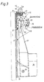
- a bearing body 30 is provided on the column 1, which is rotatable about it and can be moved up and down on it, and comprises two parts which are movable relative to one another, namely a cylinder 31 which is seated on the column 1 and can be moved and displaced this up and down movable carriage 32 (Fig. 3).
- the cylinder 31 has three bearing lugs 35 for mounting the clearing arms 36 of the three-arm 2.
- Each of the three clearing arms 36 equipped with a number of clearing coulters 37 is pivotally mounted on an axis 38 which is fixed in the associated bearing projection 35.
- the sled 32 consists of a sled upper part 33 and a sled lower part 34, which are rotatably connected to one another by a rotating ball joint 39, consisting of an inner ring 40 attached to the upper sled part 33 by screws 42 and an outer ring 41 fastened to the lower sled part 34 by means of screws 43 and balls 44.
- a rotating ball joint 39 consisting of an inner ring 40 attached to the upper sled part 33 by screws 42 and an outer ring 41 fastened to the lower sled part 34 by means of screws 43 and balls 44.
- the chain 45 runs from the lifting device 4 down to a sprocket 46 on the upper carriage part 33, from here up to a (not visible) sprocket on the platform 18, horizontally from this sprocket to a second 'sprocket 48 on the platform 18 and from there again down to a second sprocket 49 on the carriage upper part 33 and upwards from the sprocket 49 to a (not visible) fixed point on the platform 18 (FIGS. 1, 3 and 4).
- the lower carriage part 34 has receptacles 50, one of which is assigned to each clearing arm 36.
- Each clearing arm 36 is designed as an angle lever, one arm 51 points in the direction of the column 1 and is received with its free end by the associated receptacle 50 of the lower carriage part 34 in the circumferential direction without play.
- the carriage 32 can thereby move axially relative to the arms 51 of the clearing arms 36, but cannot rotate relative to the cylinder 31 or the arms 51; the receptacles 50 thus simultaneously act as a rotation lock.
- the clearing arms 36 for clearing the germinated barley from the hor To be able to adjust the floor 9 parallel to this and to be able to adjust it obliquely to it for loading the tray floor 9 with a barley grain layer that is different in height, two control elements are provided for each clearing arm 36, one of which with the bearing body 30 and with the lower carriage part 34 of his carriage 32, and the other is connected to his arm 51 to form a unit. As shown in FIG. 3, the control member connected to the arm 51 of each clearing arm 36 is designed as a control cam 52 and is fastened to it by screws 53.
- control roller 54 which is rotatably mounted in the associated receptacle 50 on an axis 55 fastened in the latter and interacts with the control cam 52 on the arm 51 assigned to this receptacle 50.
- adjusting means for fine adjustment of the sledge path are in provided in both directions of movement.
- two set screws 56, 57 are arranged on the cylinder 31 of the bearing body 30; the adjusting screw 56 is used to adjust the inclined position of the clearing arms, the adjusting screw 57 is there for adjusting the clearing arms 36 parallel to the tray bottom 9.
- Three cable strands 58 are provided for transmitting the torque or the driving force from the drive ring 19 driven by the two rotating mechanisms 3 to the clearing arms 36 and for intercepting the latter.
- Each of these rope strands 58 is anchored at both ends in a rope sleeve 59 or 60, of which the rope sleeve 59 is connected to the drive ring 19 by a bolt 61 with a suspension eye 20 and the rope sleeve 60 is connected to a suspension eye 63 attached to the clearing arm 36 by a bolt 62 is articulated.
- the barley which is fed through the feed pipe 15 and the crop inlet 13 and thereby moistened, is derived from the hood 27 in such a way that it is distributed all around the column 1 on the tray bottom 9.
- the three-arm 2 which is lowered by a corresponding actuation of the lifting device 4 to a small distance from the tray bottom 9 and driven clockwise by the two rotating mechanisms 3 by means of the drive ring 19 and the cable strands 58 (FIG. 2), distributes the barley over the whole Tray floor by taking them both in the direction of movement and conveying them radially from the center to the periphery of the tray bottom 9 due to the inclined position of the clearing shares 37 of its clearing arms 36.
- the three-arm 2 is raised by an amount corresponding to the height of the next sub-layer with the aid of the lifting device 4, which can happen during the rotary movement thanks to the ball-and-socket joint 39 provided between the upper slide part 33 and the lower slide part 34.
- the three-arm 2 correspondingly set upwards, a further layer of barley is now applied to the first layer and this process is repeated until a layer of material having the desired height is applied to the tray bottom 9 and this is leveled.
- the material layer is heaped at a lower height than in the peripheral region of the tray bottom 9, so that the material layer is given a surface which is conical or downward from the side wall 8 towards the column 1.
- the clearing arms 36 are inclined according to the desired inclination of the surface. This is done with the aid of the lifting device 4, in that, by switching on the drive motor of the latter, the slide 32 is moved upwards on the cylinder 31 by means of the chain 45 until the lower part 34 of the slide rests on the adjusting screw 56 (position of the slide 32 according to Fig. 3).
- each control roller 54 in cooperation with the control cam 52 associated therewith, has pivoted the associated arm 51 counterclockwise and thus also the clearing arm 36 connected to the latter to form a unit.
- the clearing arms 36 are thus in the inclined position or in the working position for loading the tray bottom 9 and with this setting the loading process is carried out, as explained above.
- the three-arm 2, together with the bearing body 30, is moved upwards by the lifting device 4 from the material layer to its rest position near the platform 18 and held in this position by the lifting device 4.
- the barley located on the tray 9 is then z. B. allowed to germinate for 24 hours, possibly being rewetted several times.
- the grain layer on the tray bottom 9 is acted upon by conditioned air, which a suction fan 64 (FIG. 1) sucks through the channel 65 from top to bottom through the grain layer and the perforated plates 9a of the tray bottom 9.
- This germination process extends over several days, with the batch located on the tray bottom 9 being reloaded, for example, in a 24-hour rhythm, onto the tray bottom 9 of a downstream other treatment area 5, for example a treatment area 5 directly adjacent to the floor 6, in which the discharge nozzle 10 flows.
- the caps 11 are first opened and the barley flows through the outlet openings 12 and the outlet nozzle 10 under the effect of the Gravity, with an outlet funnel forming in the grain layer.
- the three-arm 2 is lowered from its rest position by corresponding actuation of the lifting device 4 until the clearing coulters 37 of its clearing arms 36 engage in the grain layer 3, and now the turning mechanism 3 is switched on in the sense of clearing, which the clearing arms 36, which are still in an inclined position, are mediated of the drive ring 19 and the cable strands 58 counterclockwise (Fig. 2) in a rotary motion.
- the clearing arms 36 convey with their clearing shares 37 the barley in the circumferential direction forwards and radially from the outside inwards to the outlet openings 12 and into them.
- the cylinder 31 of the latter against a stop provided at the bottom of the column 1 (not illustrated) ) and is stopped by it, while the carriage 32 is moved further downwards by the device 4, namely relative to the cylinder 31 and on the latter, until the lower carriage part 34 comes to rest on the adjusting screw 57 and is stopped by it; a limit switch, not shown, switches off the drive of the lifting device 4.
- control rollers 54 also move downward and the position indicated in dash-dot lines, thereby releasing the arms 51 which, under the weight of the clearing arms 36, pivot so clockwise about the axes 38 that the clearing arms 36 move Move back from the inclined position to the horizontal position or to the position parallel to the loading area of the horizontal floor 9.
- the three-arm 2 which continues to rotate, clears the remaining barley still present on the tray bottom 9 with its clearing arms 36, which are now in parallel position, and their clearing shares 37.
- the progress achieved with the invention essentially consists in the fact that a comparatively simple loading and clearing device for malting plants, which only requires a lifting drive and a rotary drive, has been realized, which is robust and adaptable in view of the continuous use for which it is intended distinguished and whose more sensitive components and aggregates are largely protected from negative influences.
Landscapes
- Chemical & Material Sciences (AREA)
- Organic Chemistry (AREA)
- Engineering & Computer Science (AREA)
- Bioinformatics & Cheminformatics (AREA)
- Life Sciences & Earth Sciences (AREA)
- Biochemistry (AREA)
- Health & Medical Sciences (AREA)
- General Engineering & Computer Science (AREA)
- General Health & Medical Sciences (AREA)
- Genetics & Genomics (AREA)
- Food Science & Technology (AREA)
- Wood Science & Technology (AREA)
- Zoology (AREA)
- Drying Of Solid Materials (AREA)
- Treatment Of Fiber Materials (AREA)
Claims (14)
Applications Claiming Priority (2)
| Application Number | Priority Date | Filing Date | Title |
|---|---|---|---|
| DE3049107 | 1980-12-24 | ||
| DE3049107A DE3049107C2 (de) | 1980-12-24 | 1980-12-24 | Belade- und Abräumeinrichtung für Hordenböden in Mälzereien |
Publications (3)
| Publication Number | Publication Date |
|---|---|
| EP0054749A2 EP0054749A2 (fr) | 1982-06-30 |
| EP0054749A3 EP0054749A3 (en) | 1985-01-02 |
| EP0054749B1 true EP0054749B1 (fr) | 1987-05-13 |
Family
ID=6120337
Family Applications (1)
| Application Number | Title | Priority Date | Filing Date |
|---|---|---|---|
| EP81109821A Expired EP0054749B1 (fr) | 1980-12-24 | 1981-11-21 | Installation de chargement et de déchargement de claies de tourailles en malteries |
Country Status (4)
| Country | Link |
|---|---|
| EP (1) | EP0054749B1 (fr) |
| DE (2) | DE3049107C2 (fr) |
| ES (1) | ES508267A0 (fr) |
| FI (1) | FI813914A7 (fr) |
Cited By (1)
| Publication number | Priority date | Publication date | Assignee | Title |
|---|---|---|---|---|
| CN104582493A (zh) * | 2012-07-27 | 2015-04-29 | 布勒股份有限公司 | 用于窑炉干燥的材料的窑炉干燥的方法和设备 |
Families Citing this family (5)
| Publication number | Priority date | Publication date | Assignee | Title |
|---|---|---|---|---|
| DE19956341A1 (de) * | 1999-11-23 | 2001-05-31 | Buehler Ag | Vorrichtung zum Beladen von Malzdarren |
| US20050170043A1 (en) * | 2002-02-16 | 2005-08-04 | Harris Nicholas J. | Method and apparatus for malting |
| DE10230246A1 (de) * | 2002-07-04 | 2004-01-15 | Bühler AG | Mälzereianlage und Keimhorde |
| DE102005010561A1 (de) * | 2005-03-04 | 2006-09-07 | Bühler AG | Einrichtung zum Be- und Entladen von Flachbodenweichen |
| FR2946360B1 (fr) * | 2009-06-04 | 2011-06-24 | Malteurope Groupe | Dispositif de touraillage de grain ameliore |
Family Cites Families (3)
| Publication number | Priority date | Publication date | Assignee | Title |
|---|---|---|---|---|
| DD66705A (fr) * | ||||
| FR2125780A6 (fr) * | 1971-02-19 | 1972-09-29 | Nordon & Cie Sa | |
| DE2541583C3 (de) * | 1975-09-18 | 1978-03-09 | Buehler-Miag Gmbh, 3300 Braunschweig | Vorrichtung zum Einebnen und Ausräumen von Schüttgut in bzw. aus Gutbehandlungsräumen, insbesondere für Mälzereien |
-
1980
- 1980-12-24 DE DE3049107A patent/DE3049107C2/de not_active Expired
-
1981
- 1981-11-21 EP EP81109821A patent/EP0054749B1/fr not_active Expired
- 1981-11-21 DE DE8181109821T patent/DE3176185D1/de not_active Expired
- 1981-12-07 FI FI813914A patent/FI813914A7/fi not_active Application Discontinuation
- 1981-12-22 ES ES508267A patent/ES508267A0/es active Granted
Cited By (2)
| Publication number | Priority date | Publication date | Assignee | Title |
|---|---|---|---|---|
| CN104582493A (zh) * | 2012-07-27 | 2015-04-29 | 布勒股份有限公司 | 用于窑炉干燥的材料的窑炉干燥的方法和设备 |
| CN104582493B (zh) * | 2012-07-27 | 2018-01-09 | 布勒股份有限公司 | 用于窑炉干燥的材料的窑炉干燥的方法和设备 |
Also Published As
| Publication number | Publication date |
|---|---|
| ES8301272A1 (es) | 1982-12-01 |
| DE3049107C2 (de) | 1983-02-17 |
| EP0054749A3 (en) | 1985-01-02 |
| FI813914L (fi) | 1982-06-25 |
| DE3176185D1 (en) | 1987-06-19 |
| ES508267A0 (es) | 1982-12-01 |
| DE3049107A1 (de) | 1982-07-08 |
| EP0054749A2 (fr) | 1982-06-30 |
| FI813914A7 (fi) | 1982-06-25 |
Similar Documents
| Publication | Publication Date | Title |
|---|---|---|
| DE2430306A1 (de) | Dreschkorbanordnung in einer axialdreschmaschine eines maehdreschers | |
| DE2000553A1 (de) | Maehdrescher mit axialem Arbeitsfluss | |
| DE2801715C2 (de) | Beladegerät für körniges Gut in Gutbehandlungsräumen, insbesondere zum Beladen von Hordendarren in Mälzereien | |
| DE2926713A1 (de) | Vorrichtung zur befeuchtung von salzgranulaten | |
| EP0054749B1 (fr) | Installation de chargement et de déchargement de claies de tourailles en malteries | |
| DE3321326A1 (de) | Verfahren und vorrichtung zum reinigen und sortieren von schuettguetern aller art | |
| DE2147280A1 (de) | Schrot- und Mischanlage | |
| EP1641909B1 (fr) | Dispositif pour le maltage de cereales | |
| EP0085358B1 (fr) | Moissonneuse-batteuse à dispositif de battage à écoulement axial | |
| DE3103593A1 (de) | Dragiertrommel zum ueberziehen von tabletten u.dgl. | |
| DE3050671C1 (de) | Belade- und Abraeumeinrichtung fuer Hordenboeden in Maelzereien | |
| DE2742415A1 (de) | Verfahren und vorrichtung zum herstellen der feuerfesten zustellung metallurgischer gefaesse | |
| EP0001202B1 (fr) | Dispositif pour couper des produits ensilés d'un silo plat | |
| DE3151483C1 (de) | Einrichtung zum Beladen und Entladen von Hordenbödenin Mälzungsanlagen | |
| DE3407685C1 (de) | Verfahren und Anlage zum Darren von Grünmalz | |
| DE1481383A1 (de) | Verfahren und Vorrichtung zur Einlagerung von faserigem Gut in loser Schuettung | |
| DE69120451T2 (de) | Umfüllvorrichtung für Material in Turmmälzereien | |
| DE19613927C1 (de) | Verfahren und Vorrichtung zum Beschichten von Kleinteilen | |
| DE2541583C3 (de) | Vorrichtung zum Einebnen und Ausräumen von Schüttgut in bzw. aus Gutbehandlungsräumen, insbesondere für Mälzereien | |
| CH671895A5 (fr) | ||
| DE2331842C3 (de) | Verfahren und Einrichtung zum kontinuierlichen Befeuchten von cerealem Korngut vor dessen Mahlung | |
| DE8034585U1 (de) | Belade- und abraeumeinrichtung fuer hordenboeden in maelzereien | |
| DE3125110C2 (de) | Schüttgutbunker-Austragvorrichtung | |
| DE2714313A1 (de) | Maschine zum haeckseln | |
| DE8137851U1 (de) | Einrichtung zum beladen und entladen von hordenboeden in maelzungsanlagen |
Legal Events
| Date | Code | Title | Description |
|---|---|---|---|
| PUAI | Public reference made under article 153(3) epc to a published international application that has entered the european phase |
Free format text: ORIGINAL CODE: 0009012 |
|
| AK | Designated contracting states |
Designated state(s): BE DE FR GB SE |
|
| PUAL | Search report despatched |
Free format text: ORIGINAL CODE: 0009013 |
|
| AK | Designated contracting states |
Designated state(s): BE DE FR GB SE |
|
| 17P | Request for examination filed |
Effective date: 19850201 |
|
| 17Q | First examination report despatched |
Effective date: 19860120 |
|
| GRAA | (expected) grant |
Free format text: ORIGINAL CODE: 0009210 |
|
| AK | Designated contracting states |
Kind code of ref document: B1 Designated state(s): BE DE FR GB SE |
|
| PG25 | Lapsed in a contracting state [announced via postgrant information from national office to epo] |
Ref country code: SE Effective date: 19870531 |
|
| REF | Corresponds to: |
Ref document number: 3176185 Country of ref document: DE Date of ref document: 19870619 |
|
| ET | Fr: translation filed | ||
| PLBE | No opposition filed within time limit |
Free format text: ORIGINAL CODE: 0009261 |
|
| STAA | Information on the status of an ep patent application or granted ep patent |
Free format text: STATUS: NO OPPOSITION FILED WITHIN TIME LIMIT |
|
| 26N | No opposition filed | ||
| PGFP | Annual fee paid to national office [announced via postgrant information from national office to epo] |
Ref country code: DE Payment date: 19921006 Year of fee payment: 12 |
|
| PGFP | Annual fee paid to national office [announced via postgrant information from national office to epo] |
Ref country code: GB Payment date: 19921118 Year of fee payment: 12 |
|
| PGFP | Annual fee paid to national office [announced via postgrant information from national office to epo] |
Ref country code: FR Payment date: 19921123 Year of fee payment: 12 |
|
| PGFP | Annual fee paid to national office [announced via postgrant information from national office to epo] |
Ref country code: BE Payment date: 19930104 Year of fee payment: 12 |
|
| PG25 | Lapsed in a contracting state [announced via postgrant information from national office to epo] |
Ref country code: GB Effective date: 19931121 |
|
| PG25 | Lapsed in a contracting state [announced via postgrant information from national office to epo] |
Ref country code: BE Effective date: 19931130 |
|
| BERE | Be: lapsed |
Owner name: BUHLER-MIAG G.M.B.H. Effective date: 19931130 |
|
| GBPC | Gb: european patent ceased through non-payment of renewal fee |
Effective date: 19931121 |
|
| PG25 | Lapsed in a contracting state [announced via postgrant information from national office to epo] |
Ref country code: FR Effective date: 19940729 |
|
| PG25 | Lapsed in a contracting state [announced via postgrant information from national office to epo] |
Ref country code: DE Effective date: 19940802 |
|
| REG | Reference to a national code |
Ref country code: FR Ref legal event code: ST |