EP0054802A1 - Verbindung von Trägern mit einer durchgehenden Stütze - Google Patents
Verbindung von Trägern mit einer durchgehenden Stütze Download PDFInfo
- Publication number
- EP0054802A1 EP0054802A1 EP81110173A EP81110173A EP0054802A1 EP 0054802 A1 EP0054802 A1 EP 0054802A1 EP 81110173 A EP81110173 A EP 81110173A EP 81110173 A EP81110173 A EP 81110173A EP 0054802 A1 EP0054802 A1 EP 0054802A1
- Authority
- EP
- European Patent Office
- Prior art keywords
- support
- plate
- fasteners
- hook
- support plate
- Prior art date
- Legal status (The legal status is an assumption and is not a legal conclusion. Google has not performed a legal analysis and makes no representation as to the accuracy of the status listed.)
- Granted
Links
- 210000001145 finger joint Anatomy 0.000 claims abstract description 16
- 230000013011 mating Effects 0.000 claims abstract 2
- 239000003292 glue Substances 0.000 claims description 8
- 238000004026 adhesive bonding Methods 0.000 claims description 4
- 239000002023 wood Substances 0.000 claims description 2
- 230000006835 compression Effects 0.000 claims 1
- 238000007906 compression Methods 0.000 claims 1
- 238000004519 manufacturing process Methods 0.000 claims 1
- 238000000034 method Methods 0.000 description 8
- 230000000694 effects Effects 0.000 description 2
- 238000003825 pressing Methods 0.000 description 2
- 230000003313 weakening effect Effects 0.000 description 2
- 238000010521 absorption reaction Methods 0.000 description 1
- 230000005540 biological transmission Effects 0.000 description 1
- 238000010276 construction Methods 0.000 description 1
- 238000009776 industrial production Methods 0.000 description 1
- 238000009434 installation Methods 0.000 description 1
- 210000001503 joint Anatomy 0.000 description 1
- 238000003466 welding Methods 0.000 description 1
Images
Classifications
-
- E—FIXED CONSTRUCTIONS
- E04—BUILDING
- E04B—GENERAL BUILDING CONSTRUCTIONS; WALLS, e.g. PARTITIONS; ROOFS; FLOORS; CEILINGS; INSULATION OR OTHER PROTECTION OF BUILDINGS
- E04B1/00—Constructions in general; Structures which are not restricted either to walls, e.g. partitions, or floors or ceilings or roofs
- E04B1/38—Connections for building structures in general
- E04B1/58—Connections for building structures in general of bar-shaped building elements
-
- E—FIXED CONSTRUCTIONS
- E04—BUILDING
- E04B—GENERAL BUILDING CONSTRUCTIONS; WALLS, e.g. PARTITIONS; ROOFS; FLOORS; CEILINGS; INSULATION OR OTHER PROTECTION OF BUILDINGS
- E04B1/00—Constructions in general; Structures which are not restricted either to walls, e.g. partitions, or floors or ceilings or roofs
- E04B1/18—Structures comprising elongated load-supporting parts, e.g. columns, girders, skeletons
- E04B1/26—Structures comprising elongated load-supporting parts, e.g. columns, girders, skeletons the supporting parts consisting of wood
- E04B1/2604—Connections specially adapted therefor
- E04B2001/262—Connection node with interlocking of specially shaped wooden members, e.g. puzzle type connection
-
- E—FIXED CONSTRUCTIONS
- E04—BUILDING
- E04B—GENERAL BUILDING CONSTRUCTIONS; WALLS, e.g. PARTITIONS; ROOFS; FLOORS; CEILINGS; INSULATION OR OTHER PROTECTION OF BUILDINGS
- E04B1/00—Constructions in general; Structures which are not restricted either to walls, e.g. partitions, or floors or ceilings or roofs
- E04B1/18—Structures comprising elongated load-supporting parts, e.g. columns, girders, skeletons
- E04B1/26—Structures comprising elongated load-supporting parts, e.g. columns, girders, skeletons the supporting parts consisting of wood
- E04B1/2604—Connections specially adapted therefor
- E04B2001/2628—Interlocking connectors, e.g. with hooks or dovetails, added to the elongated wooden members
- E04B2001/2636—Interlocking connectors, e.g. with hooks or dovetails, added to the elongated wooden members with connectors located in slots of the wooden members
-
- E—FIXED CONSTRUCTIONS
- E04—BUILDING
- E04B—GENERAL BUILDING CONSTRUCTIONS; WALLS, e.g. PARTITIONS; ROOFS; FLOORS; CEILINGS; INSULATION OR OTHER PROTECTION OF BUILDINGS
- E04B1/00—Constructions in general; Structures which are not restricted either to walls, e.g. partitions, or floors or ceilings or roofs
- E04B1/18—Structures comprising elongated load-supporting parts, e.g. columns, girders, skeletons
- E04B1/26—Structures comprising elongated load-supporting parts, e.g. columns, girders, skeletons the supporting parts consisting of wood
- E04B1/2604—Connections specially adapted therefor
- E04B2001/2644—Brackets, gussets or joining plates
- E04B2001/2648—Brackets, gussets or joining plates located in slots of the elongated wooden members
-
- E—FIXED CONSTRUCTIONS
- E04—BUILDING
- E04B—GENERAL BUILDING CONSTRUCTIONS; WALLS, e.g. PARTITIONS; ROOFS; FLOORS; CEILINGS; INSULATION OR OTHER PROTECTION OF BUILDINGS
- E04B1/00—Constructions in general; Structures which are not restricted either to walls, e.g. partitions, or floors or ceilings or roofs
- E04B1/18—Structures comprising elongated load-supporting parts, e.g. columns, girders, skeletons
- E04B1/26—Structures comprising elongated load-supporting parts, e.g. columns, girders, skeletons the supporting parts consisting of wood
- E04B1/2604—Connections specially adapted therefor
- E04B2001/2676—Connector nodes
-
- E—FIXED CONSTRUCTIONS
- E04—BUILDING
- E04B—GENERAL BUILDING CONSTRUCTIONS; WALLS, e.g. PARTITIONS; ROOFS; FLOORS; CEILINGS; INSULATION OR OTHER PROTECTION OF BUILDINGS
- E04B1/00—Constructions in general; Structures which are not restricted either to walls, e.g. partitions, or floors or ceilings or roofs
- E04B1/18—Structures comprising elongated load-supporting parts, e.g. columns, girders, skeletons
- E04B1/26—Structures comprising elongated load-supporting parts, e.g. columns, girders, skeletons the supporting parts consisting of wood
- E04B1/2604—Connections specially adapted therefor
- E04B2001/2692—End to end connections of elongated members along their common longitudinal axis
-
- F—MECHANICAL ENGINEERING; LIGHTING; HEATING; WEAPONS; BLASTING
- F16—ENGINEERING ELEMENTS AND UNITS; GENERAL MEASURES FOR PRODUCING AND MAINTAINING EFFECTIVE FUNCTIONING OF MACHINES OR INSTALLATIONS; THERMAL INSULATION IN GENERAL
- F16B—DEVICES FOR FASTENING OR SECURING CONSTRUCTIONAL ELEMENTS OR MACHINE PARTS TOGETHER, e.g. NAILS, BOLTS, CIRCLIPS, CLAMPS, CLIPS OR WEDGES; JOINTS OR JOINTING
- F16B2200/00—Constructional details of connections not covered for in other groups of this subclass
- F16B2200/20—Connections with hook-like parts gripping behind a blind side of an element to be connected
- F16B2200/205—Connections with hook-like parts gripping behind a blind side of an element to be connected the hook being a separate retainer
-
- Y—GENERAL TAGGING OF NEW TECHNOLOGICAL DEVELOPMENTS; GENERAL TAGGING OF CROSS-SECTIONAL TECHNOLOGIES SPANNING OVER SEVERAL SECTIONS OF THE IPC; TECHNICAL SUBJECTS COVERED BY FORMER USPC CROSS-REFERENCE ART COLLECTIONS [XRACs] AND DIGESTS
- Y10—TECHNICAL SUBJECTS COVERED BY FORMER USPC
- Y10T—TECHNICAL SUBJECTS COVERED BY FORMER US CLASSIFICATION
- Y10T403/00—Joints and connections
- Y10T403/34—Branched
- Y10T403/341—Three or more radiating members
- Y10T403/345—Coplanar
-
- Y—GENERAL TAGGING OF NEW TECHNOLOGICAL DEVELOPMENTS; GENERAL TAGGING OF CROSS-SECTIONAL TECHNOLOGIES SPANNING OVER SEVERAL SECTIONS OF THE IPC; TECHNICAL SUBJECTS COVERED BY FORMER USPC CROSS-REFERENCE ART COLLECTIONS [XRACs] AND DIGESTS
- Y10—TECHNICAL SUBJECTS COVERED BY FORMER USPC
- Y10T—TECHNICAL SUBJECTS COVERED BY FORMER US CLASSIFICATION
- Y10T403/00—Joints and connections
- Y10T403/70—Interfitted members
- Y10T403/7045—Interdigitated ends
Definitions
- the invention relates to the connection of beams with a continuous support made of wood, with the help of elements as described in the preamble of main claim 1.
- the plates developed for prefabricated skeleton construction that is the support plates for the supports and the hook plates arranged on the end faces of supports, can be installed relatively easily in supports and single-storey supports.
- possibilities are also shown to install two-part support plates of special design in continuous supports by slitting, for example, orthogonally intersecting slits.
- the fastening means of the cross plate also participate in the load transmission.
- the fastening means of the cross plate also participate in the load transmission.
- one-piece support plate much greater support forces can be transmitted than with two flat, slotted plates, which are first pushed into one another in the slots.
- the invention is therefore based on the object to install one-piece, cross-shaped support plates in a continuous support industrially and rationally so that with one-sided or two-sided load introduction, the fastening elements of the cross plate participate in the absorption of these loads and the support at the connection of the carrier undergoes the smallest possible cross-sectional weakening .
- the solution to the problem is that the support is glued with glued finger joint in the area of the integrally formed support plate below the support surfaces of the support plate.
- An expedient method for making a connection is that the butt surfaces are first zinc-plated, then the support parts which are only plugged together in the zincing are planed together without glueing, that the necessary slots 5 are introduced into the support parts to be butted together and the holes for the Fasteners of the support plates are created, that the support plate 3 is inserted into the slots 5 of the support part lying below the joint, that the glue is applied to the surfaces to be glued, the surfaces provided with glue are pressed against one another and the fasteners are driven in in the compressed state, and that after. the pressing of the fasteners removes the pressure so that the curing can take place under the holding influence of the fasteners, because then the cross plate in connection with their fasteners acts as a tab and dowel element of the "glued finger joint.
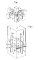
- Support 1 shows the continuous. Support 1 the finger joint 2 at the level of the recessed cross-shaped support plate 3 and the support heads provided for the connection with their hook plates 4. In the present. For example, all beams are at the same height and have the same dimensions.
- the hook plates 4 engage in the slots 5 and settle on the support plate 3. In the assembled state, the finger joint 2 is no longer visible.
- the slot 5 in the support 1 is freely accessible beyond the upper edge of the carrier. If necessary, fittings can be inserted into the slot 5, so that the support is locked with the support 1. For example, an unintentional unhooking of the carrier can be countered.
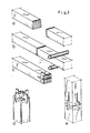
- the finger joint 2 is shown in an isometric representation as it is penetrated by the cruciform support plate 3.
- the illustration makes it clear that the cruciform support plate 3 causes the support parts to be centered and has the effect of an additional dowelling of the support surfaces.
- the rod dowels 6 shown dowel the support plate 3 with the lower support part, the rod dowels 7 with the upper support part. Due to the position of the finger joint 2 between the rod dowels 6 and 7, the support plate 3 also acts as a connecting means for the two support parts. Tensile forces on the butt joint are transmitted by the glued finger joint, but also by the dowelled support plate 3.
- 3 serves to explain the method according to the invention for installing one-piece support plates in continuous supports.
- Fig. 3 the five working phases for the process of installing cruciform support plates in continuous supports are shown.
- tines are milled into the end faces of the support parts.
- work phase b the support that has collided in the finger jointing without gluing is being processed.
- all roofs are planed together.
- the cross-shaped support plate is inserted into the lower support part, the finger joint surfaces of which have already been applied with glue, and dowelled with the dowels.
- a continuous support manufactured according to the method according to the invention has no weakening itself in the form of a cross-shaped, one-piece support plate in the joint, because the hook plate used is a lashing of the joint.
- the support itself is only weakened by the relatively narrow slots 5 above the joint.
Landscapes
- Engineering & Computer Science (AREA)
- Architecture (AREA)
- Physics & Mathematics (AREA)
- Electromagnetism (AREA)
- Civil Engineering (AREA)
- Structural Engineering (AREA)
- Joining Of Building Structures In Genera (AREA)
- Connection Of Plates (AREA)
- Paper (AREA)
- Absorbent Articles And Supports Therefor (AREA)
- Details Of Garments (AREA)
Abstract
Description
- Die Erfindung betrifft die Verbindung von Trägern mit einer durchgehenden Stütze aus Holz, mit Hilfe von Elementen, wie sie im Oberbegriff des Hauptanspruches 1 beschrieben sind.
- Bei einer bekannten Verbindung der angegebenen Art, vgl. DE-OS 28 38 053, lassen sich die für den vorgefertigten Skelettbau entwickelten Platten, das sind die Auflagerplatten für die Stützen und die an den Stirnflächen von Trägern angeordneten Hakenplatten verhältnismäßig einfach in Träger und eingeschossige Stützen einbauen. In der genannten Offenlegungsschrift sind auch Möglichkeiten aufgezeigt, in durchgehende Stützen durch Einschlitzen von beispielsweise orthogonal sich kreuzenden Schlitzen zweigeteilte Auflagerplatten mit besonderer Ausführung einzubauen. Diese, in den Schlitzen ineinander steckbaren Platten, haben den Nachteil, daß die Last nur von der Platte abgetragen wird, in die der Haken des Trägers eingreift.
- Bei starren, durch Verschweißung miteinander verbundenen oder auch stranggepreßten, einstückigen Kreuzungsplatten dagegen beteiligen sich auch die Befestigungsmittel der Querplatte an der Lastübertragung. Namentlich bei einseitiger, aber auch bei zweiseitiger Lasteinleitung in eine kreuzförmige, einstückige Auflagerplatte können wesentlich größere Auflagerkräfte übertragen werden, als bei zwei ebenen, geschlitzten Platten, die in den Schlitzen erst zu einem Kreuz ineinander geschoben werden.
- Der Erfindung liegt daher die Aufgabe zugrunde, einstückige, kreuzförmige Auflagerplatten in eine durchgehende Stütze industriell und rationell so einzubauen, daß bei einseitiger oder zweiseitiger Lasteinleitung die Befestigungselemente der Querplatte sich an der Aufnahme dieser Lasten beteiligen und die Stütze am Anschluß der Träger eine kleinstmögliche Querschnittsschwächung erfährt.
- Die Lösung der gestellten Aufgabe besteht darin, daß die Stütze mit verleimtem Keilzinkenstoß im Bereich der einstückig ausgebildeten Auflagerplatte unterhalb der Auflagerflächen der Auflagerplatte gestoßen ist. Beim erfindungsgemäßen Zusammenleimen der Stützenteile im Keilzinkenstoß wird erreicht, daß die Auflagerplatte die Wirkung eines Zentrierteils für beide Stützenteile übernimmt, so daß eine paßgenaue Zusammenfügung zwangsläufig erreicht wird.
- Das Zusammenfügen. von Holzquerschnitten durch Keilzinkenverleimung zu einem biegesteifen Querschnitt ist eine bekannte Technik. Dennoch liegt es für den Fachmann keineswegs nahe, den Keilzinkenstoß dorthin zu legen, wo er von der Auflagerplatte mindestens in einer Richtung durchdrungen wird. Man würde eher erwarten, daß der Keilzinkenstoß ans obere Ende des Schlitzes verlegt wird, weil dann der Schlitz nur in die Stirnfläche des unteren Stützenteils eingefräst werden müßte.
- Ein zweckmäßiges Verfahren zum Herstellen einer Verbindung besteht darin, daß zunächst die Stoßflächen gezinkt werden, daß dann die in der Zinkung nur zusammengesteckten Stützenteile ohne Verleimung gemeinsam gehobelt werden, daß die notwendigen Schlitze 5 jeweils in die miteinander zu stoßenden Stützenteile eingebracht und die Bohrungen für die Befestigungsmittel der Auflagerplatten erstellt werden, daß die Auflagerplatte 3 in die Schlitze 5 des unterhalb des Stoßes liegenden Stützenteils eingesteckt wird, daß auf die zu verleimenden Flächen der Leim aufgetragen wird, die mit Leim versehenen Flächen gegeneinander gepreßt und im verpreßten Zustand die Befestigungsmittel eingetrieben werden, und daß nach. dem Eintreiben der Befestigungsmittel die Verpressung aufgehoben wird, so daß die Aushärung unter dem haltenden Einfluß der Befestigungsmittel stattfinden kann, weil dann die Kreuzplatte in Verbindung mit deren Befestigungsmittel als Lasche und Verdübelungselement des" geleimten Keilzinkenstoßes wirksam wird.
- Die Erfindung wird nachstehend an einem Ausführungsbeispiel erläutert, es zeigt:
- Fig. 1 in isometrischer Darstellung einen Skelettknoten mit einer Stütze und mit 4 Trägern in orthogonaler Anordnung,
- Fig. 2 in isometrischer Darstellung die Lage des Keilzinkenstoßes zur Auflagerplatte,
- Fig. 3 in isometrischer Darstellung schematisiert die Arbeitstakte des Verfahrens zum Einbau kreuzförmiger Auflagerplatten in durchgehende Stützen.
- In Fig. 1 zeigt die durchgehende. Stütze 1 den Keilzinkenstoß 2 in Höhe der eingelassenen kreuzföxmigen Auflagerplatte 3 und die für den Anschluß vorgesehenen Trägerköpfe mit ihren Hakenplatten 4. Im vorliegenden. Beispiel liegen alle Träger in derselben Höhe und besitzen die gleichen Abmessungen. Die Hakenplatten 4 greifen in die Schlitze 5 ein und setzen sich auf die Auflagerplatte 3 ab. Im zusammengefügten Zustand ist der Keilzinkenstoß 2 nicht mehr sichtbar. Über die Oberkante der Träger hinaus ist der Schlitz 5 in der Stütze 1 frei zugänglich. Im Bedarfsfall lassen sich Paßstücke in den Schlitz 5 einfügen, so daß es zu einer Verriegelung der Träger mit der Stütze 1 kommt. So könnte z.B. einem unbeabsichtigten Aushängen der Träger begegnet werden.
- In Fig. 2 sind in isometrischer Darstellung der Keilzinkenstoß 2 dargestellt, wie er von der kreuzförmigen Auflagerplatte 3 durchdrungen wird. Die Darstellung macht deutlich, daß die kreuzförmige Auflagerplatte 3 eine Zentrierung der Stützenteile bewirkt und sich wie eine zusätzliche Verdübelung der Stützenflächen auswirkt. Die dargestellten Stabdübel 6 verdübeln die Auflagerplatte 3 mit dem unteren Stützenteil, die Stabdübel 7 mit dem oberen Stützenteil. Durch die Lage des Keilzinkenstoßes 2 zwischen den Stabdübeln 6 und 7 wirkt sich die Auflagerplatte 3 auch als Verbindungsmittel der beiden Stützenteile aus. Zugkräfte auf den Stützenstoß werden von der verleimten Keilzinkung, aber auch von der eingedübelten Auflagerplatte 3 übertragen.
- Zur Erläuterung des erfindungsmäßigen Verfahrens zum Einbau von einstückigen Auflagerplatten in durchgehende Stützen dient Fig. 3.
- In Fig. 3 sind die fünf Arbeitsphasen zum Verfahren des Einbaus kreuzförmiger Auflagerplatten in durchgehende Stützen dargestellt.
- In der Arbeitsphase a werden in die Stirnflächen der Stützenteile Zinken gefräst.
- In der Arbeitsphase b ist die in der Keilzinkung ohne Verleimung zusammengestoßene Stütze in Bearbeitung. Alle -dächen werden beispielsweise gemeinsam gehobelt.
- In der Arbeitsphase c ist die durch Keilzinken vorbereitete Stirnfläche dargestellt, wie sie Bohrungen für die Stabdübel und die Schlitze erhält.
- In der Arbeitsphase d ist in den unteren Stützenteil, dessen Keilzinkenflächen bereits einen Leimauftrag erhalten haben, die kreuzförmige Auflagerplatte eingesetzt und mit den Stabdübeln verdübelt.
- In der Arbeitsphase e wird der obere Stützenteil aufgepreßt, auch die anderen Stabdübel werden eingeschlagen, die den geleimten Stützenstoß nunmehr sichern und eine längere Verpressung unnötig machen.
- Am Beispiel der durchgehenden quadratischen Stütze wurde das . Verfahren des Einbaus von Auflagerplatten in durchgehende Stützen erläutert. Bei der industriellen Fertigung stellt sich diese Art des Einbaus insofern als sehr rationell heraus, als ein Überschuß an in der Keilzinkung aufgetragenem Leim keine nachteiligen Folgen haben kann. Würde der Keilzinkenstoß oberhalb der Auflagerplatten liegen, so würde der aus der Keilzinkung in die Schlitze 5 austretende Überschußleim ausgehärtet, eine Behinderung beim Einfädeln der Hakenplatte darstellen oder gar die Auflagerflächen für die Hakenplatte verlegen, so daß die erforderliche Maßgenauigkeit des Zusammenbaus nicht mehr gewährleistet wäre. Bei dem Einbau nach dem erfindungsmäßigen Verfahren kann der Überschußleim eine derartige Verlegung der Schlitze nicht verursachen.
- Darüberhinaus besitzt eine nach dem erfingunsgemäßen Verfahren hergestellte durchgehende Stütze.- mft kreuzförmiger, einstückiger Auflagerplatte im Stoß selbst keine Schwächung, weil die eingesetzte Hakenplatte eine Laschung des Stoßes darstellt. Die Stütze selbst ist nur durch die relativ schmalen Schlitze 5 oberhalb des Stoßes geschwächt.
Claims (2)
Applications Claiming Priority (2)
| Application Number | Priority Date | Filing Date | Title |
|---|---|---|---|
| DE3046790 | 1980-12-12 | ||
| DE3046790A DE3046790C2 (de) | 1980-12-12 | 1980-12-12 | Verbindung von Trägern mit einer durchgehenden Stütze und Verfahren zum Herstellen einer derartigen Verbindung |
Publications (2)
| Publication Number | Publication Date |
|---|---|
| EP0054802A1 true EP0054802A1 (de) | 1982-06-30 |
| EP0054802B1 EP0054802B1 (de) | 1984-03-14 |
Family
ID=6118955
Family Applications (1)
| Application Number | Title | Priority Date | Filing Date |
|---|---|---|---|
| EP81110173A Expired EP0054802B1 (de) | 1980-12-12 | 1981-12-04 | Verbindung von Trägern mit einer durchgehenden Stütze |
Country Status (13)
| Country | Link |
|---|---|
| US (1) | US4558968A (de) |
| EP (1) | EP0054802B1 (de) |
| JP (1) | JPS57123345A (de) |
| AT (1) | AT374536B (de) |
| CA (1) | CA1161621A (de) |
| DE (1) | DE3046790C2 (de) |
| DK (1) | DK150909C (de) |
| FI (1) | FI68286C (de) |
| GE (1) | GEP19960486B (de) |
| HU (1) | HU181392B (de) |
| NO (1) | NO155455C (de) |
| SU (1) | SU1153839A3 (de) |
| YU (1) | YU42004B (de) |
Cited By (6)
| Publication number | Priority date | Publication date | Assignee | Title |
|---|---|---|---|---|
| WO2014120028A1 (en) | 2013-01-29 | 2014-08-07 | Ux2 Centrum Technologiczne Sp. Z.O.O. | The lock of the connection set for structural elements, the connection set with locks and the method of joining constructional elements with the use of the connection set |
| EP3321452A1 (de) * | 2016-11-14 | 2018-05-16 | ZÜBLIN Timber Aichach GmbH | Bauelement aus holz |
| US10626594B2 (en) | 2017-02-24 | 2020-04-21 | New World China Land Limited | Fabricated structural system and assembling method thereof |
| CN111364624A (zh) * | 2020-04-14 | 2020-07-03 | 重庆渝建实业集团股份有限公司 | 一种新型钢-混凝土组合梁柱节点 |
| EP3665343A4 (de) * | 2017-10-12 | 2021-05-26 | Charitou, George | Bauelement |
| EP2453739B2 (de) † | 2009-07-14 | 2023-03-01 | Basf Se | Verfahren zur herstellung einer wässrigen suspension eines organischen pestiziden wirkstoffs |
Families Citing this family (36)
| Publication number | Priority date | Publication date | Assignee | Title |
|---|---|---|---|---|
| DE3914618A1 (de) * | 1989-05-03 | 1990-11-08 | Bulldog Beratung | Verbindungselement fuer (holz-)balken |
| US5061111A (en) * | 1991-01-02 | 1991-10-29 | Kiyoshi Hosokawa | Metal connector for wooden building and jointing structure of wooden building using the same |
| JPH0754405Y2 (ja) * | 1991-03-11 | 1995-12-18 | 清司 細川 | 木造建築材用締結金具と木造建築物の締結構造 |
| US5342138A (en) * | 1991-12-27 | 1994-08-30 | Nitto Mokuzai Sangyo Kabushiki Kaisha | Connectors for structural members |
| US5253945A (en) * | 1991-12-31 | 1993-10-19 | Kiyoshi Hosokawa | Metal connector for building and jointing structure of building using the same |
| JP2879392B2 (ja) * | 1992-04-17 | 1999-04-05 | カトウ産業株式会社 | 木造建築用軸組構造及び軸組具 |
| US5577856A (en) * | 1993-08-10 | 1996-11-26 | Tezuka; Junichi | Beam support system for forming precompressed wood joints |
| JP3301568B2 (ja) * | 1993-08-25 | 2002-07-15 | 林建設工業株式会社 | 建造物の施工方法 |
| JP2594130Y2 (ja) * | 1993-10-13 | 1999-04-19 | 株式会社学習研究社 | 画像を利用した外国語会話学習書 |
| JP3066734B2 (ja) * | 1996-11-15 | 2000-07-17 | 株式会社ウエスト | 木造の建物の軸組用装置 |
| JP3066735B2 (ja) * | 1996-11-19 | 2000-07-17 | 株式会社ウエスト | 木造建物の木材柱連結金具 |
| JP3390823B2 (ja) * | 1996-11-20 | 2003-03-31 | 株式会社ウエスト | 木造建物の軸組用装置 |
| DE19828835C1 (de) * | 1998-06-27 | 1999-07-29 | Dornier Gmbh | Zugstab zur Verwendung als Gurt für Brücken |
| US20080107480A1 (en) * | 2004-06-30 | 2008-05-08 | Svein Berg | Joining system, individual elements and method for use thereof |
| RU2360077C2 (ru) * | 2005-02-14 | 2009-06-27 | Тартунтамарккинойнти Ой | Скрытое консольное соединение |
| DE502005009457D1 (de) * | 2005-06-23 | 2010-06-02 | Neue Holzbau Ag Lungern | Biegesteife oder gelenkige und steckbare Verbindung für Tragwerkselemente |
| US20110280649A1 (en) * | 2010-05-11 | 2011-11-17 | William Dewson Architects Inc. | Construction joints and related connectors |
| JP5822262B2 (ja) * | 2011-06-30 | 2015-11-24 | 住友林業株式会社 | 梁勝ち接合部における柱梁接合構造 |
| CN202287029U (zh) * | 2011-09-06 | 2012-07-04 | 奇立科技有限公司 | 易于拆装的组合式家具 |
| JP6164646B2 (ja) * | 2013-10-22 | 2017-07-19 | 住友林業株式会社 | 柱脚部接合構造 |
| US9920531B1 (en) * | 2015-03-09 | 2018-03-20 | Connecticut Post & Beam LLC | Post and beam system |
| EP3061882A4 (de) * | 2015-04-16 | 2017-06-14 | Nice Holdings, Inc. | Rahmenbesfestigung |
| CA2895868A1 (fr) * | 2015-06-30 | 2016-12-30 | Unipi Canada Inc. | Systeme constructif pour batiments modulaires evolutifs permanents et demontables |
| DE102016204921A1 (de) * | 2016-03-24 | 2017-09-28 | Swg Schraubenwerk Gaisbach Gmbh | Verbinder und Verfahren zum Verbinden von Balken aus Holzwerkstoff |
| CA2984664C (en) | 2016-11-07 | 2026-04-07 | Simpson Strong-Tie Company, Inc. | Concealed joist tie with sloped center flange |
| CN106760192A (zh) * | 2016-11-24 | 2017-05-31 | 杨阳 | 一种锁扣结构的组合式房屋立柱 |
| WO2018101101A1 (ja) * | 2016-11-30 | 2018-06-07 | 株式会社飯田産業 | 建築物およびその建築工法 |
| GB2554967B (en) * | 2017-06-12 | 2020-12-09 | Eqrbs Ltd | A joint |
| US11280080B2 (en) | 2017-06-12 | 2022-03-22 | Peter James Bucklitsch | Kit for defining a recess for a single or multi-way joint |
| CN108560753B (zh) * | 2018-04-20 | 2019-11-01 | 青岛理工大学 | 带有颗粒阻尼仓耗能的装配式智能节点及安装方法 |
| CN109811904B (zh) * | 2019-03-07 | 2024-05-17 | 毛国庆 | 一种木梁与混凝土柱的榫卯节点结构及其施工方法 |
| US11230838B1 (en) * | 2019-09-08 | 2022-01-25 | Wilfredo Mendez-Vazquez | Structural steel plug for bi-axial moment connections |
| US11525255B2 (en) | 2020-05-04 | 2022-12-13 | Columbia Insurance Company | Concealed structural connector |
| BE1028755B1 (nl) * | 2020-10-29 | 2022-05-31 | Bewerk | Bouw verbinding |
| CN113187153A (zh) * | 2021-04-20 | 2021-07-30 | 中国市政工程西北设计研究院有限公司 | 一种抗震增强型支撑柱 |
| CA3252020A1 (en) * | 2022-04-18 | 2023-10-26 | Simpson Strong-Tie Company Inc. | Heavy seat knife plate hanger |
Citations (3)
| Publication number | Priority date | Publication date | Assignee | Title |
|---|---|---|---|---|
| DE1904738A1 (de) * | 1969-01-31 | 1970-08-20 | Jakob Pink | Kreuzverbindungsstueck fuer Balken und Stuetzen |
| CH500349A (de) * | 1970-02-23 | 1970-12-15 | Gygax Peter | Abgestützter Knotenpunkt in einer Balkenlage |
| DE2838053A1 (de) * | 1978-08-31 | 1980-03-20 | Streif Ohg | Verbindung fuer zusammenfuegbare skelettkonstruktionen |
Family Cites Families (6)
| Publication number | Priority date | Publication date | Assignee | Title |
|---|---|---|---|---|
| US674752A (en) * | 1900-10-29 | 1901-05-21 | Ball Bearing Shade Roller Company | Extensible shade-roller. |
| US1099771A (en) * | 1913-05-26 | 1914-06-09 | Guy P Slater | Derrick. |
| CH166686A (de) * | 1933-01-02 | 1934-01-31 | Fontana J Th | Blockwand für Holzbauten. |
| US3355196A (en) * | 1965-12-13 | 1967-11-28 | Minnesota Mining & Mfg | Smooth joint for structural sheets and members |
| SE324650B (de) * | 1966-06-29 | 1970-06-08 | Hombak Maschinenfab Kg | |
| IT1005294B (it) * | 1974-02-15 | 1976-08-20 | Artevetrina Srl | Sistema di piu elementi per la formazione di strutture composte in particolare strutture per arredamenti |
-
1980
- 1980-12-12 DE DE3046790A patent/DE3046790C2/de not_active Expired
-
1981
- 1981-12-01 HU HU813613A patent/HU181392B/hu not_active IP Right Cessation
- 1981-12-01 US US06/326,418 patent/US4558968A/en not_active Expired - Fee Related
- 1981-12-04 EP EP81110173A patent/EP0054802B1/de not_active Expired
- 1981-12-07 YU YU2851/81A patent/YU42004B/xx unknown
- 1981-12-08 SU SU813362300A patent/SU1153839A3/ru active
- 1981-12-09 AT AT0525581A patent/AT374536B/de not_active IP Right Cessation
- 1981-12-11 JP JP56200796A patent/JPS57123345A/ja active Granted
- 1981-12-11 DK DK549681A patent/DK150909C/da not_active IP Right Cessation
- 1981-12-11 NO NO814245A patent/NO155455C/no unknown
- 1981-12-11 FI FI813998A patent/FI68286C/fi not_active IP Right Cessation
- 1981-12-11 CA CA000392087A patent/CA1161621A/en not_active Expired
-
1992
- 1992-07-20 GE GEAP199285A patent/GEP19960486B/en unknown
Patent Citations (3)
| Publication number | Priority date | Publication date | Assignee | Title |
|---|---|---|---|---|
| DE1904738A1 (de) * | 1969-01-31 | 1970-08-20 | Jakob Pink | Kreuzverbindungsstueck fuer Balken und Stuetzen |
| CH500349A (de) * | 1970-02-23 | 1970-12-15 | Gygax Peter | Abgestützter Knotenpunkt in einer Balkenlage |
| DE2838053A1 (de) * | 1978-08-31 | 1980-03-20 | Streif Ohg | Verbindung fuer zusammenfuegbare skelettkonstruktionen |
Cited By (9)
| Publication number | Priority date | Publication date | Assignee | Title |
|---|---|---|---|---|
| EP2453739B2 (de) † | 2009-07-14 | 2023-03-01 | Basf Se | Verfahren zur herstellung einer wässrigen suspension eines organischen pestiziden wirkstoffs |
| WO2014120028A1 (en) | 2013-01-29 | 2014-08-07 | Ux2 Centrum Technologiczne Sp. Z.O.O. | The lock of the connection set for structural elements, the connection set with locks and the method of joining constructional elements with the use of the connection set |
| EP3321452A1 (de) * | 2016-11-14 | 2018-05-16 | ZÜBLIN Timber Aichach GmbH | Bauelement aus holz |
| US10626594B2 (en) | 2017-02-24 | 2020-04-21 | New World China Land Limited | Fabricated structural system and assembling method thereof |
| EP3665343A4 (de) * | 2017-10-12 | 2021-05-26 | Charitou, George | Bauelement |
| US11686108B2 (en) | 2017-10-12 | 2023-06-27 | George CHARITOU | Prop head assembly |
| US12084874B2 (en) | 2017-10-12 | 2024-09-10 | George CHARITOU | Construction component |
| CN111364624A (zh) * | 2020-04-14 | 2020-07-03 | 重庆渝建实业集团股份有限公司 | 一种新型钢-混凝土组合梁柱节点 |
| CN111364624B (zh) * | 2020-04-14 | 2022-05-17 | 渝建实业集团股份有限公司 | 一种钢-混凝土组合梁柱节点 |
Also Published As
| Publication number | Publication date |
|---|---|
| SU1153839A3 (ru) | 1985-04-30 |
| JPS57123345A (en) | 1982-07-31 |
| JPS6344902B2 (de) | 1988-09-07 |
| EP0054802B1 (de) | 1984-03-14 |
| FI813998L (fi) | 1982-06-13 |
| DK150909B (da) | 1987-07-13 |
| AT374536B (de) | 1984-05-10 |
| YU285181A (en) | 1984-06-30 |
| NO155455C (no) | 1987-04-01 |
| ATA525581A (de) | 1983-09-15 |
| DK549681A (da) | 1982-06-13 |
| GEP19960486B (en) | 1996-07-10 |
| DE3046790A1 (de) | 1982-06-24 |
| HU181392B (en) | 1983-07-28 |
| US4558968A (en) | 1985-12-17 |
| YU42004B (en) | 1988-04-30 |
| DK150909C (da) | 1988-06-06 |
| FI68286B (fi) | 1985-04-30 |
| NO814245L (no) | 1982-06-14 |
| DE3046790C2 (de) | 1982-11-11 |
| CA1161621A (en) | 1984-02-07 |
| NO155455B (no) | 1986-12-22 |
| FI68286C (fi) | 1985-08-12 |
Similar Documents
| Publication | Publication Date | Title |
|---|---|---|
| EP0054802B1 (de) | Verbindung von Trägern mit einer durchgehenden Stütze | |
| DE2838053C3 (de) | Verbindung für zusammenfügbare Skelettkonstruktionen | |
| EP0641901A1 (de) | Montage-Bausystem für ein Holzhaus | |
| DE202004015772U1 (de) | Dachrand-Verbinder | |
| DE3903770A1 (de) | Verbindungs-stuetze zur erstellung von containergehaeusen bzw. fertigbau-raumkoerpern | |
| DE2143579A1 (de) | Vorgefertigtes Holzhaus | |
| DE19958923A1 (de) | Holzschiene für ein Fahrgeschäft sowie Verfahren zur Herstellung und zum Montieren einer solchen Holzschiene | |
| DE3444305A1 (de) | Baueinheit zur bildung einer wand, decke oder tuer einer sauna- oder dampfbadkabine | |
| CH665672A5 (de) | Schalungsvorrichtung. | |
| DE69605777T2 (de) | Verfahren zum errichten von mauern aus glasbausteinen und ein dabei zur anwendung kommendes bewehrbares modulares element | |
| DE1199468B (de) | Wandkonstruktion unter Verwendung vorgefertigter Bautafeln | |
| EP0034820A2 (de) | Geleimter Holzfachwerkträger und unter Verwendung desselben gebildete Schalung | |
| CH683443A5 (de) | Blockhausartiges Gebäude. | |
| DE1609898B1 (de) | Stossausbildung fuer hoelzerne Hallentraeger od.dgl.aus verleimten Lamellen | |
| DE2649576A1 (de) | Schwalbenschwanzverbindung bzw. lasttragender bauteil mit selbstklemmvernutung | |
| DE3007277C2 (de) | Verfahren zum Vorbereiten von Sparren für die Errichtung von Sparren- und Kehlriegeldachstühlen und Sparrenwiderlager zur Durchführung dieses Verfahrens | |
| DE4200455A1 (de) | Verfahren zum verbinden von holzbauteilen | |
| EP1148181B1 (de) | Holztragelement | |
| DE29622127U1 (de) | Spannschloß sowie Elementverband insbesondere für den Holzelementbau | |
| DE1609898C (de) | ||
| DE2416646C3 (de) | Flachdachbelag | |
| DE2101483A1 (de) | Steckprofile für den Dachbau | |
| DE3439824A1 (de) | Bauelementesatz zur erstellung eines unterbaues zum aufbau von fahrtrassen fuer modellfahrzeuge | |
| EP0150331A2 (de) | Schalungselement für Innenecke | |
| DE19653362A1 (de) | Spannschloß sowie Elementverband insbesondere für den Holzelementbau |
Legal Events
| Date | Code | Title | Description |
|---|---|---|---|
| PUAI | Public reference made under article 153(3) epc to a published international application that has entered the european phase |
Free format text: ORIGINAL CODE: 0009012 |
|
| AK | Designated contracting states |
Designated state(s): CH FR GB LI NL SE |
|
| 17P | Request for examination filed |
Effective date: 19820622 |
|
| GRAA | (expected) grant |
Free format text: ORIGINAL CODE: 0009210 |
|
| AK | Designated contracting states |
Designated state(s): CH FR GB LI NL SE |
|
| ET | Fr: translation filed | ||
| PLBE | No opposition filed within time limit |
Free format text: ORIGINAL CODE: 0009261 |
|
| STAA | Information on the status of an ep patent application or granted ep patent |
Free format text: STATUS: NO OPPOSITION FILED WITHIN TIME LIMIT |
|
| 26N | No opposition filed | ||
| PGFP | Annual fee paid to national office [announced via postgrant information from national office to epo] |
Ref country code: FR Payment date: 19941208 Year of fee payment: 14 |
|
| PGFP | Annual fee paid to national office [announced via postgrant information from national office to epo] |
Ref country code: SE Payment date: 19941215 Year of fee payment: 14 |
|
| PGFP | Annual fee paid to national office [announced via postgrant information from national office to epo] |
Ref country code: NL Payment date: 19941231 Year of fee payment: 14 |
|
| PGFP | Annual fee paid to national office [announced via postgrant information from national office to epo] |
Ref country code: CH Payment date: 19950120 Year of fee payment: 14 |
|
| EAL | Se: european patent in force in sweden |
Ref document number: 81110173.2 |
|
| PGFP | Annual fee paid to national office [announced via postgrant information from national office to epo] |
Ref country code: GB Payment date: 19951124 Year of fee payment: 15 |
|
| PG25 | Lapsed in a contracting state [announced via postgrant information from national office to epo] |
Ref country code: SE Effective date: 19951205 |
|
| PG25 | Lapsed in a contracting state [announced via postgrant information from national office to epo] |
Ref country code: LI Effective date: 19951231 Ref country code: CH Effective date: 19951231 |
|
| PG25 | Lapsed in a contracting state [announced via postgrant information from national office to epo] |
Ref country code: NL Effective date: 19960701 |
|
| REG | Reference to a national code |
Ref country code: CH Ref legal event code: PL |
|
| PG25 | Lapsed in a contracting state [announced via postgrant information from national office to epo] |
Ref country code: FR Effective date: 19960830 |
|
| NLV4 | Nl: lapsed or anulled due to non-payment of the annual fee |
Effective date: 19960701 |
|
| REG | Reference to a national code |
Ref country code: FR Ref legal event code: ST |
|
| PG25 | Lapsed in a contracting state [announced via postgrant information from national office to epo] |
Ref country code: GB Effective date: 19961204 |
|
| GBPC | Gb: european patent ceased through non-payment of renewal fee |
Effective date: 19961204 |