EP0054932B1 - Mécanisme d'attelage pour tout système de véhicules de chemins de fer miniatures - Google Patents
Mécanisme d'attelage pour tout système de véhicules de chemins de fer miniatures Download PDFInfo
- Publication number
- EP0054932B1 EP0054932B1 EP81110589A EP81110589A EP0054932B1 EP 0054932 B1 EP0054932 B1 EP 0054932B1 EP 81110589 A EP81110589 A EP 81110589A EP 81110589 A EP81110589 A EP 81110589A EP 0054932 B1 EP0054932 B1 EP 0054932B1
- Authority
- EP
- European Patent Office
- Prior art keywords
- draw
- bar
- guide
- guide form
- transverse piece
- Prior art date
- Legal status (The legal status is an assumption and is not a legal conclusion. Google has not performed a legal analysis and makes no representation as to the accuracy of the status listed.)
- Expired
Links
- 230000008878 coupling Effects 0.000 title claims description 18
- 238000010168 coupling process Methods 0.000 title claims description 18
- 238000005859 coupling reaction Methods 0.000 title claims description 18
- 239000000872 buffer Substances 0.000 claims description 6
- 241000511343 Chondrostoma nasus Species 0.000 description 3
- 239000000853 adhesive Substances 0.000 description 3
- 238000004026 adhesive bonding Methods 0.000 description 3
- 230000001070 adhesive effect Effects 0.000 description 3
- 230000007935 neutral effect Effects 0.000 description 3
- 239000004033 plastic Substances 0.000 description 3
- 229920003023 plastic Polymers 0.000 description 3
- 230000007704 transition Effects 0.000 description 3
- 239000011324 bead Substances 0.000 description 2
- 238000010276 construction Methods 0.000 description 2
- 238000004519 manufacturing process Methods 0.000 description 2
- 229920001169 thermoplastic Polymers 0.000 description 2
- 239000004416 thermosoftening plastic Substances 0.000 description 2
- 229920005176 Hostaform® Polymers 0.000 description 1
- 238000005299 abrasion Methods 0.000 description 1
- 230000002349 favourable effect Effects 0.000 description 1
- 238000001746 injection moulding Methods 0.000 description 1
- 239000000463 material Substances 0.000 description 1
- 239000002184 metal Substances 0.000 description 1
- 229910052751 metal Inorganic materials 0.000 description 1
- 150000002739 metals Chemical class 0.000 description 1
- 238000000034 method Methods 0.000 description 1
- 125000006850 spacer group Chemical group 0.000 description 1
- 238000003860 storage Methods 0.000 description 1
- 239000000725 suspension Substances 0.000 description 1
Images

Classifications
-
- A—HUMAN NECESSITIES
- A63—SPORTS; GAMES; AMUSEMENTS
- A63H—TOYS, e.g. TOPS, DOLLS, HOOPS OR BUILDING BLOCKS
- A63H19/00—Model railways
- A63H19/16—Parts for model railway vehicles
- A63H19/18—Car coupling or uncoupling mechanisms
Definitions
- the invention relates to a device for guiding couplings on model railroad vehicles of any system according to the preamble of claim 1.
- the invention is based on the object of designing the clutch guide system of the type mentioned at the outset, which enables smooth driving when driving straight ahead and when cornering, the buffers gliding past adjacent vehicle ends without the risk of snagging, in such a way that the «drawbar extension» necessary when cornering
- the coupling pin is pushed out as soon as the tiller arm swings out of the longitudinal axis of the tiller - neutral center position.
- this system should make do with a minimum number of individual parts and thus be inexpensive to manufacture, as well as allow maintenance-free operation and enable smooth operation even with small radii of curvature of the rails.
- the clutch guide system according to the invention should be easily attachable to both new and older models from any manufacturer.
- this object is achieved in a device according to the preamble of claim 1 by the features listed in the characterizing part of this claim.
- the subject matter of the invention achieves improved guidance of the carriages compared to the prior art, and the assembly or attachment of the coupling, which consists of only a few individual parts and occupies an area of less than 6 cm 2 -Leadership system much easier, especially since the latter only has a total height of about 2 mm.
- the small number of individual parts also significantly reduces manufacturing, storage and assembly costs.
- maintenance-free operation can be guaranteed through the use of wear-resistant and self-lubricating plastic parts.
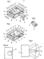
- the device for guiding couplings on model railway vehicles essentially consists of a guide template 1 and a T-shaped drawbar 2, which consists of the crosspiece 3 and the drawbar leg 4 extending in the direction of the drawbar longitudinal axis DL puts.
- the tiller arm 4 can optionally be provided at its free front end or in the region of the cross piece 3 with a pin 5, which for connecting and compensating for height differences with the receiving piece 6 shown in FIG. 3 for the coupling (not shown) on the coupling to be coupled Trolley serves.
- the receptacle 6 has a recess 7 corresponding to the shape of the pin 5 for receiving the pin 5, on which the receptacle 6 can be adjusted to the required height, possibly with spacers, and can be fastened, for example, by gluing.
- the guide template 1 is shown in FIGS. 1 and 4 open at the bottom and can be closed by a cover plate 8 with the help of the pins 9 attached there by pushing into the recesses 10 made in the guide template 1.
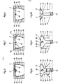
- the rear edge 11 of the crosspiece 3 of the T-shaped drawbar 2 lies against the rear edge 12 of the guide template 1 without play.
- the free end pieces 17, 18 of the cross piece 3 point against the corners 15, 16 of the guide template 1 formed by the curved or straight ends of the curved branches 13, 14 and the rear edge 12 of the guide template 1.
- the end pieces 17, 18 of the tiller cross piece 3 lying in these corners 15, 16 when driving straight ahead lie down either directly on the curved guide surfaces 23, 24 or curved branches 13, 14 of the guide template 1 without play (FIGS. 5 and 9) or they come to rest at the transition point 19, 20 of a straight part 21, 22 to the curved guide surfaces 23, 24 of the curved branches 13, 14 (FIG. 7).
- the corner 16 serves as a fulcrum for the T-shaped drawbar 2 and the free end of the leg 4 with the pin 5 executes the path designated B in FIG. 2.
- the tiller arm 4 with the pin 5 is pushed further out of the guide template 1. In this way the buffers of the coupled carriages can be guided past one another without getting caught.
- cornering against the direction of arrow 25 the same process takes place in the opposite direction, see the path labeled A in FIG. 2.
- springs 26 are attached to the crosspiece 3, which run practically parallel to the longitudinal axis of the drawbar DL and are attached approximately in the middle of the corresponding inclined surfaces 27 of the crosspiece 3. In some cases it may also be advantageous to mount the springs at an angle a of approximately 20 ° to 50 ° to the longitudinal axis DL of the drawbar, as is illustrated in FIG. 6 by the springs 28 shown in solid lines. To increase the spring force, several parallel springs or a combination of parallel and oblique springs - as indicated in FIG. 6 - can also be provided.
- the nose 30 attached to the rear edge 12 of the guide template 1 can either be arranged rigidly or else movably under the pressure of a spring 31 and thus snap into the recess 32 and exert pressure on the drawbar 2. This increases their ease of movement.
- the drawbar 2 has one or two recesses 7 'or 7 ", into which a corresponding pin 5 can optionally be introduced on the receiving piece 6.
- the recesses 7', 7" or the pin 5 can, however, also in the sense of a kinematic reversal be interchanged. If the recess 7 ′ made in the crosspiece 3 of the drawbar 2 is used, the end of the drawbar that is not required can be broken off at a predetermined breaking point 33.
- the lower cover plate 8 has a preferably triangular cutout 37 with rounded corners through which the coupling pin 5 engages with any tiller position.
- the play-free mounting of the drawbar 2 according to FIG. 8 is achieved in that on the rear edge 12 of the guide template 1, provided with or without a nose 30, a straight section 21 or 22 at right angles on both sides Guide surface of the rear edge 12 is mounted upright, which merges into the curved branches 23, 24 of the guide template 1 at points 19, 20.
- the end pieces 17, 18 of the cross piece 3 are shaped so that they rest in the normal position (straight ahead) on the rear edge 12 and the transition points 19, 20 to the curved branches 23, 24.
- springs 26 or inclined springs 28 or combinations of the springs 26, 28 are provided in each case parallel to the longitudinal axis DL of the drawbar.
- the recess 32 can in turn be semicircular and thus correspond to the shape of the nose 30.
- the rear longitudinal side 11 of the drawbar crosspiece 3 with a V-shaped incision, the apex of which, in accordance with the radius of the nose 30, is preferably rounded, while the parts adjoining the apex end in straight lines 32a, 32b ( see dashed line in Fig. 8).
- the arrangement can also be made such that the straight lines 32a, 32b form an obtuse angle of more than 120 °, preferably 150 °, without rounding.
- the continuously curved branches 13, 14 are brought up to the rear edge 12 of the guide template 1, against which the rear edge 11 of the T-shaped drawbar 2 shown in FIG. 10 fits snugly.
- the slope of the curved branches 13, 14 is so great that with a pulling force acting on the leg 4 of the drawbar 2 in the direction of the longitudinal axis DL of the shaft, the tapered end pieces 17, 18 immediately against the guide surfaces 23, 24 of the curved branches 13, 14 Concerns come, ie that there is no play between the guide surfaces 23, 24 and the drawbar 2.
- the curved branches 13, 14 preferably form sections of cries, the center points of which lie at the outer end points of the rear edge 12 of the guide template 1.
- the springs 26, 28 are preferably leaf springs, which are advantageously formed in one piece with the T-shaped drawbar 2.
- a particularly suitable material for the drawbar 2 and the springs 26, 28 is a thermoplastic known under the trade name “Hostaform”, which is characterized by favorable suspension and sliding properties as well as high mechanical strength. In principle, however, other types of abrasion-resistant plastics or metals can also be used.
- pins 9 are provided there, which are inserted into corresponding recesses 10 in the guide template 1 and can be coated beforehand with adhesive for additional gluing. It has proven to be advantageous to make the recesses on 3 reinforced edge parts of the guide template 1, to be precise - if present - in the region of the guide lug 30 and in the two opposite reinforced edge parts which adjoin the curved branches 13, 14.
- the crosspiece 3 of the drawbar 2 can also be provided with a continuously flat longitudinal side 34 which bears against a centrally arranged guide lug 35 of the guide template 1.
- the guide lug 35 is preferably semicircular.
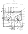
- the T-shaped drawbar 2 rests with its rear cross piece surface (long side 34) on the one hand on the semicircular guide nose 35 at point 36 and on the other hand with the two end pieces 37, 38 on the guide surfaces 39, 40 narrowing towards the front the guide template 1.
- the lateral guide surfaces 39, 40 of the guide template 1 in turn form circular sections, the center of which in each case lie at the outer end points 41, 42 of the rear, inner longitudinal side 43 of the guide template 1.
- the springs which are operatively connected to the lateral guide surfaces 39, 40 are numbered 44, 45.
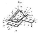
- the springs 44, 45 in the form of leaf springs nestle against the guide surfaces 39, 40 of the guide template 1, these springs 44, 45 in turn in the rounded transition region 46 between the crosspiece 3 and the longitudinal leg 4 of the Drawbar 2 attached, preferably integrally formed on the drawbar 2.
- T-shaped drawbar 2 is supported at three points, namely in the upper right corner 41 of the guide template 1, at point 47 in the front part of the left guide surface 40 and with its drawbar leg 4 or the associated leaf spring 44 at the end point 48 of the opposite one Guide surface 39 of the guide template 1.
- the pivoting of the T-shaped drawbar 2 into the other possible extreme position is analogous.
- the leaf springs 44, 45 preferably have the same or approximately the same height as the height H of the guide surfaces 39, 40 of the guide template 1 (see FIG. 11).
- the lower cover plate 49 shown in FIG. 11 it is provided with pins 50, which are inserted into corresponding recesses 51, 52, 53 of the guide template 1 and possibly coated beforehand with adhesive. It has proven to be advantageous to make the recesses 51, 52, 53 on three reinforced edge parts of the guide template 1, specifically in the region of the guide lug 35 and in the two parts formed by the parts 54, 55 of the guide surfaces 39, 40 bent outwards , reinforced edge parts 56, 57 of the guide template 1.
- the arrangement according to the invention can also be made in all the exemplary embodiments in such a way that the rear longitudinal side 12 or 43 of the guide template 1 rounds in each case over a radius, as denoted in FIG. 7 with 15a and 16a, without edges into the lateral guide surfaces 13, 14 or 39, 40 of the guide template 1 passes.
- the inner surface of the guide template 1 has at least approximately the shape of a heart curve.
- an end part of the base plate of a model railroad vehicle is designated 58, which is firmly connected on its underside to the clutch guide system, for example by gluing.
- the cover plate 49 of the guide template 1 can also be attached with a drop of plastic adhesive.
- the movable tiller arm 4 protrudes a little beyond the bottom end and carries the receiving pin 5 in a known manner.
- the T-shaped tiller 2 can also 180 ° rotated in the guide template 1 so that the mounting pin 5 is directed upwards.
- the invention is characterized above all by the fact that the desired «drawbar extension» takes place immediately from the neutral center position when the lateral drawbar is shifted.
- the clutch guide system requires very few individual parts, all of which can be manufactured inexpensively, preferably using the injection molding process when using thermoplastics.
- the clutch guide system according to the invention is characterized by an extremely flat and at the same time lightweight and reliable construction, which nevertheless ensures a very long service life.
Landscapes
- Agricultural Machines (AREA)
Claims (15)
Priority Applications (1)
| Application Number | Priority Date | Filing Date | Title |
|---|---|---|---|
| AT81110589T ATE12186T1 (de) | 1980-12-19 | 1981-12-18 | Vorrichtung zum fuehren von kupplungen an modelleisenbahnfahrzeugen beliebiger systeme. |
Applications Claiming Priority (6)
| Application Number | Priority Date | Filing Date | Title |
|---|---|---|---|
| DE3047971 | 1980-12-19 | ||
| DE3047971 | 1980-12-19 | ||
| DE19813103283 DE3103283C2 (de) | 1980-12-19 | 1981-01-31 | Aufnahmevorrichtung für eine Kupplung an einem Modelleisenbahnfahrzeug |
| DE3103283 | 1981-01-31 | ||
| DE19813130728 DE3130728A1 (de) | 1981-08-03 | 1981-08-03 | Vorrichtung zum fuehren von kupplungen an modelleisenbahnfahrzeugen beliebiger systeme |
| DE3130728 | 1981-08-03 |
Publications (3)
| Publication Number | Publication Date |
|---|---|
| EP0054932A2 EP0054932A2 (fr) | 1982-06-30 |
| EP0054932A3 EP0054932A3 (en) | 1982-10-27 |
| EP0054932B1 true EP0054932B1 (fr) | 1985-03-20 |
Family
ID=27189017
Family Applications (1)
| Application Number | Title | Priority Date | Filing Date |
|---|---|---|---|
| EP81110589A Expired EP0054932B1 (fr) | 1980-12-19 | 1981-12-18 | Mécanisme d'attelage pour tout système de véhicules de chemins de fer miniatures |
Country Status (2)
| Country | Link |
|---|---|
| EP (1) | EP0054932B1 (fr) |
| DE (1) | DE3169478D1 (fr) |
Families Citing this family (2)
| Publication number | Priority date | Publication date | Assignee | Title |
|---|---|---|---|---|
| DE3520856A1 (de) * | 1985-06-11 | 1986-12-11 | Wolfgang 4300 Essen Schuller | Kupplungsvorrichtung an einem modelleisenbahnfahrzeug |
| AT386755B (de) * | 1986-08-08 | 1988-10-10 | Moser Dieter | Vorrichtung zur lagerung einer ein kupplungselement tragenden deichsel |
Family Cites Families (2)
| Publication number | Priority date | Publication date | Assignee | Title |
|---|---|---|---|---|
| DE1478534A1 (de) * | 1963-09-02 | 1969-06-19 | Maerklin & Cie Gmbh Geb | Vorrichtung zum Rueckstellen von Anhaengerkupplungshaelften fuer Spielfahrzeuge |
| DE2035932C3 (de) * | 1970-07-20 | 1981-08-20 | Gebr. Märklin & Cie GmbH, 7320 Göppingen | Kupplungslagerung an einem Fahrspielzeug |
-
1981
- 1981-12-18 DE DE8181110589T patent/DE3169478D1/de not_active Expired
- 1981-12-18 EP EP81110589A patent/EP0054932B1/fr not_active Expired
Also Published As
| Publication number | Publication date |
|---|---|
| DE3169478D1 (en) | 1985-04-25 |
| EP0054932A2 (fr) | 1982-06-30 |
| EP0054932A3 (en) | 1982-10-27 |
Similar Documents
| Publication | Publication Date | Title |
|---|---|---|
| DE69901167T2 (de) | Klapptisch | |
| DE2449555A1 (de) | Transportwagen | |
| DD298734A5 (de) | Fuehrung fuer einen auszug, einen schubkasten od. dgl. | |
| DE3813049A1 (de) | Gleitschuh, insbesondere fuer fahrzeugschiebedaecher | |
| DE2338075A1 (de) | Karteistaender | |
| DE1950336A1 (de) | Kupplung fuer Fahrzeuge von Modelleisenbahnen | |
| DE4320989C1 (de) | Fahrzeug für elektrische Spiel- und Modellbahnen mit einem bei Kurvenfahrt nach innen neigbaren Wagenkasten | |
| DE3047055A1 (de) | Transporteinrichtung | |
| DE2048373C2 (de) | Kraftfahrzeugfaltschiebedach | |
| EP0225354B1 (fr) | Dispositif de connexion de modeles reduits de wagons de chemin de fer | |
| EP0054932A2 (fr) | Mécanisme d'attelage pour tout système de véhicules de chemins de fer miniatures | |
| DE3923677A1 (de) | Winkelsensor fuer den winkel zwischen den laengsachsen eines zugfahrzeugs und eines anhaengers | |
| DE3130728A1 (de) | Vorrichtung zum fuehren von kupplungen an modelleisenbahnfahrzeugen beliebiger systeme | |
| EP0399145A1 (fr) | Arrêt de porte pour portes de véhicules automobiles | |
| DE3202507C2 (de) | Lagervorrichtung für ein längsachsig verschiebbares und schwenkbares Teleskoprohr am Fahrzeugschiebedach | |
| DE3103283A1 (de) | Vorrichtung zum fuehren von kupplungen an modelleisenbahnfahrzeugen beliebiger systeme | |
| DE2637870C3 (de) | Sicherheitsskibindung | |
| DE10022448A1 (de) | Außenrückblickspiegel für Fahrzeuge, vorzugseise für Kraftfahrzeuge | |
| DE102024124167A1 (de) | Stützfuß für Campingfahrzeuge | |
| DE2023201C3 (de) | Schleppfördersystem mit Wagen, die mindestens einen Wählstift aufweisen | |
| DE202018106541U1 (de) | Führungsvorrichtung für Schiebetüren | |
| DE1455233C3 (fr) | ||
| DE3347084C2 (de) | Kurzkupplung für elektrische Spiel- und Modellbahnen | |
| EP0084812B1 (fr) | Dispositif pour empêcher le croisement des skis | |
| CH661755A5 (de) | Einrichtung an einer naehmaschine mit kulisse zum einstellen der stichbreite oder stichlaenge. |
Legal Events
| Date | Code | Title | Description |
|---|---|---|---|
| PUAI | Public reference made under article 153(3) epc to a published international application that has entered the european phase |
Free format text: ORIGINAL CODE: 0009012 |
|
| AK | Designated contracting states |
Designated state(s): AT CH DE FR IT NL |
|
| PUAL | Search report despatched |
Free format text: ORIGINAL CODE: 0009013 |
|
| AK | Designated contracting states |
Designated state(s): AT CH DE FR IT NL |
|
| 17P | Request for examination filed |
Effective date: 19830207 |
|
| ITF | It: translation for a ep patent filed | ||
| GRAA | (expected) grant |
Free format text: ORIGINAL CODE: 0009210 |
|
| AK | Designated contracting states |
Designated state(s): AT CH DE FR IT LI NL |
|
| PG25 | Lapsed in a contracting state [announced via postgrant information from national office to epo] |
Ref country code: NL Effective date: 19850320 |
|
| REF | Corresponds to: |
Ref document number: 12186 Country of ref document: AT Date of ref document: 19850415 Kind code of ref document: T |
|
| REF | Corresponds to: |
Ref document number: 3169478 Country of ref document: DE Date of ref document: 19850425 |
|
| ET | Fr: translation filed | ||
| NLV1 | Nl: lapsed or annulled due to failure to fulfill the requirements of art. 29p and 29m of the patents act | ||
| PLBE | No opposition filed within time limit |
Free format text: ORIGINAL CODE: 0009261 |
|
| STAA | Information on the status of an ep patent application or granted ep patent |
Free format text: STATUS: NO OPPOSITION FILED WITHIN TIME LIMIT |
|
| 26N | No opposition filed | ||
| PGFP | Annual fee paid to national office [announced via postgrant information from national office to epo] |
Ref country code: AT Payment date: 19861126 Year of fee payment: 6 |
|
| PGFP | Annual fee paid to national office [announced via postgrant information from national office to epo] |
Ref country code: FR Payment date: 19881230 Year of fee payment: 8 |
|
| ITTA | It: last paid annual fee | ||
| PG25 | Lapsed in a contracting state [announced via postgrant information from national office to epo] |
Ref country code: AT Effective date: 19891218 |
|
| PG25 | Lapsed in a contracting state [announced via postgrant information from national office to epo] |
Ref country code: LI Effective date: 19891231 Ref country code: CH Effective date: 19891231 |
|
| PG25 | Lapsed in a contracting state [announced via postgrant information from national office to epo] |
Ref country code: FR Effective date: 19900831 |
|
| REG | Reference to a national code |
Ref country code: CH Ref legal event code: PL |
|
| PG25 | Lapsed in a contracting state [announced via postgrant information from national office to epo] |
Ref country code: DE Effective date: 19900901 |
|
| REG | Reference to a national code |
Ref country code: FR Ref legal event code: ST |