EP0054967A2 - Système de chargement de toner utilisant une cartouche à marbre de serrage mobile - Google Patents
Système de chargement de toner utilisant une cartouche à marbre de serrage mobile Download PDFInfo
- Publication number
- EP0054967A2 EP0054967A2 EP81110707A EP81110707A EP0054967A2 EP 0054967 A2 EP0054967 A2 EP 0054967A2 EP 81110707 A EP81110707 A EP 81110707A EP 81110707 A EP81110707 A EP 81110707A EP 0054967 A2 EP0054967 A2 EP 0054967A2
- Authority
- EP
- European Patent Office
- Prior art keywords
- toner
- neck
- cartridge
- filler neck
- filling
- Prior art date
- Legal status (The legal status is an assumption and is not a legal conclusion. Google has not performed a legal analysis and makes no representation as to the accuracy of the status listed.)
- Ceased
Links
Images
Classifications
-
- G—PHYSICS
- G03—PHOTOGRAPHY; CINEMATOGRAPHY; ANALOGOUS TECHNIQUES USING WAVES OTHER THAN OPTICAL WAVES; ELECTROGRAPHY; HOLOGRAPHY
- G03G—ELECTROGRAPHY; ELECTROPHOTOGRAPHY; MAGNETOGRAPHY
- G03G15/00—Apparatus for electrographic processes using a charge pattern
- G03G15/06—Apparatus for electrographic processes using a charge pattern for developing
- G03G15/08—Apparatus for electrographic processes using a charge pattern for developing using a solid developer, e.g. powder developer
- G03G15/0822—Arrangements for preparing, mixing, supplying or dispensing developer
- G03G15/0865—Arrangements for supplying new developer
- G03G15/0867—Arrangements for supplying new developer cylindrical developer cartridges, e.g. toner bottles for the developer replenishing opening
- G03G15/087—Developer cartridges having a longitudinal rotational axis, around which at least one part is rotated when mounting or using the cartridge
-
- G—PHYSICS
- G03—PHOTOGRAPHY; CINEMATOGRAPHY; ANALOGOUS TECHNIQUES USING WAVES OTHER THAN OPTICAL WAVES; ELECTROGRAPHY; HOLOGRAPHY
- G03G—ELECTROGRAPHY; ELECTROPHOTOGRAPHY; MAGNETOGRAPHY
- G03G2215/00—Apparatus for electrophotographic processes
- G03G2215/06—Developing structures, details
- G03G2215/066—Toner cartridge or other attachable and detachable container for supplying developer material to replace the used material
- G03G2215/0663—Toner cartridge or other attachable and detachable container for supplying developer material to replace the used material having a longitudinal rotational axis, around which at least one part is rotated when mounting or using the cartridge
- G03G2215/0673—Generally vertically mounting of said toner cartridge parallel to its longitudinal rotational axis
-
- G—PHYSICS
- G03—PHOTOGRAPHY; CINEMATOGRAPHY; ANALOGOUS TECHNIQUES USING WAVES OTHER THAN OPTICAL WAVES; ELECTROGRAPHY; HOLOGRAPHY
- G03G—ELECTROGRAPHY; ELECTROPHOTOGRAPHY; MAGNETOGRAPHY
- G03G2215/00—Apparatus for electrophotographic processes
- G03G2215/06—Developing structures, details
- G03G2215/066—Toner cartridge or other attachable and detachable container for supplying developer material to replace the used material
- G03G2215/0663—Toner cartridge or other attachable and detachable container for supplying developer material to replace the used material having a longitudinal rotational axis, around which at least one part is rotated when mounting or using the cartridge
- G03G2215/0678—Bottle shaped container having a bottle neck for toner discharge
Definitions
- the invention relates generally to laser copying machines, in particular to a system for filling toner into such machines.
- Laser copying machines such as IBM Model 3800 use a carbon type toner similar to that used in xerographic photocopying machines and computer print-out machines.
- This toner is in the form of a fine powder that is extremely dirty and difficult to remove when spilled, and it is difficult to load the toner into the machine from conventional containers without spilling it.
- the toner is packaged in a plastic bag, and to load toner into the machine it is necessary to lift the splicing table out of its normal operating position, fill in the toner, return the splicing table to the operating position and put the machine back into operation put. This process takes about 10-15 minutes.
- Another object of the innovation is to provide a system of the type mentioned above in which toner spillage can be substantially avoided.
- the innovation is based on the object of enabling a quick and easy filling of toner into the machine in a system of the type mentioned above, without switching off the machine.
- a toner cartridge which has an emptying opening which can be closed by a position-adjustable closing plate.
- a fill neck is movably attached to the machine to receive the cartridge, and a pin within the fill neck cooperates with the striker plate to move the cartridge away from the emptying opening when the cartridge is inserted into the fill neck.
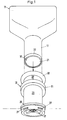
- the toner filling system comprises a cartridge 11 in which the toner is packed and an assembly with a filling neck 12 which is mounted on the copying machine to facilitate the transfer of toner from the cartridge into the machine .
- the cartridge 11 comprises a body part 16 and a neck part 17.
- the neck part extends outwards from one side of the body part.
- the body part is essentially rectangular and the neck part is essentially cylindrical.
- the corners of the body part are rounded and the walls of the body part that adjoin the neck part are inclined to ensure a smooth, smooth transition between the two areas of the container.
- the neck portion from the body portion extends at an angle in the order of 135 0th
- the body part and the neck part of the container are as a hollow, unitary structure made of a suitable material such as e.g. rigid or semi-rigid plastic, and inside the cartridge is a certain amount of (not shown) toner material.
- an emptying opening 19 is formed at the distal end of the neck part of the cartridge, i.e. at the end opposite the body part 16, an emptying opening 19 is formed.
- This emptying opening is closed and sealed by a movable locking plate 21 made of unbreakable material.
- the closing plate In its sealing position, the closing plate is resiliently held by a retaining ring 22 which is fastened to the neck part 17.
- the closing plate 21 has an outer flange 23 which is detachably held in a groove formed between the axially opposing front sides of the neck part and the retaining ring.
- the locking plate is made of unbreakable, semi-rigid plastic material and it creates a liquid-tight seal for the cartridge.
- the striker plate can be moved out of its sealing position by application of an inward force.
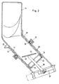
- the filler 2 is attached to the copier in a movable connection with the toner hopper of the device.
- the filler neck is provided with a connecting element 26 which has outer projections 27 for engagement with a suitable connecting element on the device side.
- a lower tubular section 28 extends upward from the connecting element 26 and is connected to an upper tubular section 29 by a retaining ring 31.
- the tubular portions 28, 29 are generally cylindrical and of slightly larger diameter than the neck portion 17 of the toner cartridge, whereby the neck portion of the cartridge can be telescopically inserted into the fill neck.
- the outer end portion 32 of the upper tubular portion 29 is flared outwardly to facilitate insertion of the cartridge into the filler neck and an annular seal 33 cooperates with the outer wall of the neck portion, creating a movable seal between the toner cartridge and the fill neck is created.
- the filler neck extends upwards and outwards from the copying machine at an angle relative to the vertical of approximately 45 °. This tendency is particularly desirable in devices such as the IBM Model 3800, where the entrance to the toner hopper is below the splicing table.
- the fill neck When the fill neck is positioned as shown, it extends from below the splicing table and the outer end of the fill neck is accessible from outside the copier without interfering with the splicing table.
- the angle of inclination of the filler neck is provided in addition to the angle between the body part and the neck part of the toner cartridge, so that in the end the body part of the cartridge is arranged vertically above the outer end of the filler neck, provided the cartridge is oriented as shown in Fig. 2. In this position the cartridge does not hinder the use of the splicing table or the other functions of the device.
- Means are provided to move the closure plate 21 away from the emptying opening of the toner cartridge while the cartridge is being inserted into the fill neck.
- These means comprise a pin 36 which is fixed in a stationary position on a cross piece 37 at the lower end of the filler neck. This pin extends upwards within the filler neck in the axial direction and is arranged such that when the neck part of the cartridge is inserted into the filler neck of the closing plate it supplies an inward force and thus moves the closing plate away from the emptying opening.
- the mode of operation and operation of the toner filling system is now as follows:
- the filling neck is mounted on the copying machine and aligned in the manner shown in FIG. 2.
- the closed, sealed toner cartridge is inserted into the filler neck and rotated into the position shown in FIG. 2, that is, into a position in which the body part extends in a substantially vertical direction.
- the closing plate 21 abuts the upper end of the pin 36 and is moved further away from the emptying opening, whereupon the toner quickly and freely through the opening from the cartridge into the machine flows.
- the striker plate has a larger diameter than the discharge opening and because the striker plate is made of unbreakable material, after it has been pushed away from the discharge opening, it will remain in the cartridge instead of falling into the machine.
- the locking plate is moved out of position by the pin 36, it is moved away from the emptying opening so that this opening is completely unblocked and the toner is free through the opening can flow.
- the innovation has a number of important features and advantages.
- the toner is housed in a cartridge that remains tightly closed until the cartridge is inserted a certain amount into the fill neck.
- the seal is then automatically and completely removed and the toner can flow freely into the copier.
- After the fill neck does not interfere with the normal operation of the machine, it can be left in the operating position on the machine, and to refill the toner it is therefore only necessary to insert a new cartridge into the fill neck. This enables fast, effective supply of toner with little likelihood of toner spillage or completely without toner spillage.
Landscapes
- Physics & Mathematics (AREA)
- General Physics & Mathematics (AREA)
- Dry Development In Electrophotography (AREA)
- Wet Developing In Electrophotography (AREA)
Applications Claiming Priority (2)
| Application Number | Priority Date | Filing Date | Title |
|---|---|---|---|
| US219962 | 1980-12-24 | ||
| US06/219,962 US4371015A (en) | 1980-12-24 | 1980-12-24 | Toner loading system having cartridge with displaceable diaphragm |
Publications (2)
| Publication Number | Publication Date |
|---|---|
| EP0054967A2 true EP0054967A2 (fr) | 1982-06-30 |
| EP0054967A3 EP0054967A3 (fr) | 1982-08-25 |
Family
ID=22821453
Family Applications (1)
| Application Number | Title | Priority Date | Filing Date |
|---|---|---|---|
| EP81110707A Ceased EP0054967A3 (fr) | 1980-12-24 | 1981-12-23 | Système de chargement de toner utilisant une cartouche à marbre de serrage mobile |
Country Status (8)
| Country | Link |
|---|---|
| US (1) | US4371015A (fr) |
| EP (1) | EP0054967A3 (fr) |
| JP (1) | JPS57164768A (fr) |
| CA (1) | CA1178431A (fr) |
| DE (1) | DE3150209A1 (fr) |
| FR (1) | FR2496915A1 (fr) |
| GB (1) | GB2089689A (fr) |
| IT (1) | IT8125770A0 (fr) |
Cited By (3)
| Publication number | Priority date | Publication date | Assignee | Title |
|---|---|---|---|---|
| WO1985000902A1 (fr) * | 1983-08-12 | 1985-02-28 | Franz Büttner Ag | Dispositif pour le remplissage de toner |
| EP0106569A3 (en) * | 1982-09-21 | 1985-04-03 | Xerox Corporation | Device for transferring particulate material |
| EP0261643A3 (en) * | 1986-09-24 | 1988-06-01 | Mita Industrial Co. Ltd. | Cartridge discriminating system |
Families Citing this family (14)
| Publication number | Priority date | Publication date | Assignee | Title |
|---|---|---|---|---|
| US4453579A (en) * | 1982-05-27 | 1984-06-12 | Gould Gerry E | Fuel sump drainage tool |
| DE3343910A1 (de) * | 1982-12-03 | 1984-06-07 | Ricoh Co., Ltd., Tokio/Tokyo | Verfahren zum zufuehren einer tonermenge und tonerbehaelter zur durchfuehrung des verfahrens |
| GB2132593A (en) * | 1982-12-24 | 1984-07-11 | Donald Smith | Fuel transport and storage |
| US4561567A (en) * | 1984-01-20 | 1985-12-31 | Pitney Bowes Inc. | Toner loading apparatus |
| JPS63110182A (ja) * | 1986-10-29 | 1988-05-14 | 株式会社村田製作所 | 電子部品チツプ収納カセツト |
| JPH0233168A (ja) * | 1988-07-22 | 1990-02-02 | Konica Corp | 複写機のトナーカートリッジ |
| US5064101A (en) * | 1989-10-31 | 1991-11-12 | The Coca-Cola Company | Five gallon nestable plastic syrup container |
| US5232125A (en) * | 1991-10-08 | 1993-08-03 | Portola Packaging, Inc. | Non-spill bottle cap used with water dispensers |
| US5472026A (en) * | 1994-07-05 | 1995-12-05 | T.B.S. Printware Corporation | Toner loading system having a swiveling extendible filler snout |
| JP3997112B2 (ja) * | 2002-05-24 | 2007-10-24 | キヤノン株式会社 | 現像剤補給装置 |
| US6778801B1 (en) | 2003-04-07 | 2004-08-17 | Hewlett-Packard Development Company, L.P. | Image-forming device and method with adjustable toner chamber cavity |
| US20050279348A1 (en) * | 2004-06-18 | 2005-12-22 | Dara Cheng | Locking stove control knob shield and safety apparatus |
| JP6960731B2 (ja) * | 2016-12-08 | 2021-11-05 | 藤森工業株式会社 | 容器の注出用スパウト |
| WO2021029335A1 (fr) | 2019-08-09 | 2021-02-18 | キヤノン株式会社 | Contenant de toner |
Family Cites Families (14)
| Publication number | Priority date | Publication date | Assignee | Title |
|---|---|---|---|---|
| US1092673A (en) * | 1913-10-31 | 1914-04-07 | William Charles Stephens | Hose coupling or union. |
| GB250105A (en) | 1925-09-23 | 1926-04-08 | Karl Martin Ferdinand Bachstro | Improvements in preserving vessels |
| GB915467A (en) | 1960-07-23 | 1963-01-16 | Thomas Herbert Threlfall | A dispensing device |
| US3670728A (en) * | 1970-06-01 | 1972-06-20 | Cutter Lab | Apparatus for intravenous administration of a fluid from a dual-chamber flask having an internal upset-table septum normally separating two axially-in-line chambers and having a pierceable end stopper |
| US3880214A (en) * | 1971-03-31 | 1975-04-29 | Nolte Albert C Jr | Attachments for preventing fuel pilferage and incorrect fuel supply |
| US3915208A (en) * | 1973-07-24 | 1975-10-28 | Inforex | Toner supply apparatus with replenishing container |
| US3941270A (en) * | 1974-01-25 | 1976-03-02 | Allied Chemical Corporation | Removable seal for liquid containers |
| US4062385A (en) * | 1975-03-14 | 1977-12-13 | Eastman Kodak Company | Toner handling apparatus |
| US4060105A (en) * | 1975-09-11 | 1977-11-29 | Xerox Corporation | Toner loading apparatus with replenishing supply container |
| GB1505878A (en) | 1975-09-18 | 1978-03-30 | Simon Solitec Ltd | Transportable container for solid particulate materials |
| GB1559252A (en) | 1977-04-14 | 1980-01-16 | Rex Rotary International | Supply of toner powder in a developer for an electrostatographic copier |
| NL7710685A (en) * | 1977-09-29 | 1979-04-02 | Tuboplast France Societe Anony | Liq. soap vessel refilling system - uses calibrated bottle and has spigots clipping on soap vessel and screwing into bottle neck |
| US4274455A (en) * | 1979-04-13 | 1981-06-23 | Tbs, Inc. | Toner loading device |
| US4304273A (en) * | 1979-12-31 | 1981-12-08 | International Business Machines Corporation | Toner container and toner dispensing apparatus |
-
1980
- 1980-12-24 US US06/219,962 patent/US4371015A/en not_active Expired - Lifetime
-
1981
- 1981-12-18 DE DE19813150209 patent/DE3150209A1/de not_active Withdrawn
- 1981-12-22 IT IT8125770A patent/IT8125770A0/it unknown
- 1981-12-23 FR FR8124102A patent/FR2496915A1/fr active Pending
- 1981-12-23 JP JP56208984A patent/JPS57164768A/ja active Pending
- 1981-12-23 EP EP81110707A patent/EP0054967A3/fr not_active Ceased
- 1981-12-23 CA CA000393057A patent/CA1178431A/fr not_active Expired
- 1981-12-23 GB GB8138859A patent/GB2089689A/en active Pending
Cited By (3)
| Publication number | Priority date | Publication date | Assignee | Title |
|---|---|---|---|---|
| EP0106569A3 (en) * | 1982-09-21 | 1985-04-03 | Xerox Corporation | Device for transferring particulate material |
| WO1985000902A1 (fr) * | 1983-08-12 | 1985-02-28 | Franz Büttner Ag | Dispositif pour le remplissage de toner |
| EP0261643A3 (en) * | 1986-09-24 | 1988-06-01 | Mita Industrial Co. Ltd. | Cartridge discriminating system |
Also Published As
| Publication number | Publication date |
|---|---|
| GB2089689A (en) | 1982-06-30 |
| IT8125770A0 (it) | 1981-12-22 |
| US4371015A (en) | 1983-02-01 |
| FR2496915A1 (fr) | 1982-06-25 |
| JPS57164768A (en) | 1982-10-09 |
| DE3150209A1 (de) | 1982-07-22 |
| EP0054967A3 (fr) | 1982-08-25 |
| CA1178431A (fr) | 1984-11-27 |
Similar Documents
| Publication | Publication Date | Title |
|---|---|---|
| EP0054967A2 (fr) | Système de chargement de toner utilisant une cartouche à marbre de serrage mobile | |
| DE2544817B2 (de) | Spender fuer fluessige seife | |
| DE3426739A1 (de) | Zwei-komponenten-packung | |
| EP0336415A2 (fr) | Dispositif de pulvérisation | |
| DE3721308A1 (de) | Verfahren zum befuellen und anschliessenden verschweissen eines behaelters sowie vorrichtung und behaelter zur durchfuehrung dieses verfahrens | |
| DE3201035C2 (de) | Gebinde für Zweikomponentensysteme | |
| DE4429662A1 (de) | Behälter | |
| DE2350825A1 (de) | Vorrichtung zur aufbewahrung und abgabe von fluessigkeit | |
| EP0310933A2 (fr) | Dispositif avec au moins un réservoir d'admission pour la conservation et la délivrance d'une substance | |
| DE60123084T2 (de) | Flexibler Behälter zum Gebrauch in einem Flüssigkeisspender | |
| DE2250887A1 (de) | Weinende puppe | |
| EP0064949A1 (fr) | Fermeture de récipient permettant l'adaptation d'un dispositif de soutirage | |
| DE69724197T2 (de) | Tonernachfüllvorrichtung in einem bilderzeugenden Gerät und zugehörige Tonerkassette | |
| DE2061144A1 (de) | Behaelter fuer Fluessigkeiten | |
| DE2262384C3 (de) | Spender für die bemessene Abgabe von pulverförmigem Material oder dergleichen | |
| DE69215573T2 (de) | Abflussreinigerausgabeeinrichtung mit Verriegelungselement | |
| DE3544748C2 (fr) | ||
| DE8137513U1 (de) | Kopiergerät mit einem Tonerbehälter und einem Toneinfülltrichter | |
| DE69702915T2 (de) | Vorratsbehälter | |
| DE69806099T2 (de) | Vorrichtung zum Entleeren von Pulver aus einem Sack | |
| DE8705463U1 (de) | Auswechselbare flexible Innenhuelle fuer Behaelter | |
| DE69208084T2 (de) | Selbstdichtender Verschluss für einen flexiblen Behälter | |
| DE8603167U1 (de) | Ausgießvorrichtung für Behälter | |
| DE69624074T2 (de) | Durchflusswegwählvorrichtung | |
| EP0598965A1 (fr) | Fermeture pour une cartouche |
Legal Events
| Date | Code | Title | Description |
|---|---|---|---|
| PUAI | Public reference made under article 153(3) epc to a published international application that has entered the european phase |
Free format text: ORIGINAL CODE: 0009012 |
|
| PUAL | Search report despatched |
Free format text: ORIGINAL CODE: 0009013 |
|
| AK | Designated contracting states |
Designated state(s): CH DE FR GB IT |
|
| AK | Designated contracting states |
Designated state(s): CH DE FR GB IT |
|
| ITCL | It: translation for ep claims filed |
Representative=s name: DR. ING. A. RACHELI & C. |
|
| 17P | Request for examination filed |
Effective date: 19821014 |
|
| STAA | Information on the status of an ep patent application or granted ep patent |
Free format text: STATUS: THE APPLICATION HAS BEEN REFUSED |
|
| 18R | Application refused |
Effective date: 19840629 |
|
| RIN1 | Information on inventor provided before grant (corrected) |
Inventor name: SIMONS, PETER B. |