EP0054973B1 - Dispositif de fabrication de rouleaux de bandes formées à partir de feuilles souples imbriqueés - Google Patents
Dispositif de fabrication de rouleaux de bandes formées à partir de feuilles souples imbriqueés Download PDFInfo
- Publication number
- EP0054973B1 EP0054973B1 EP81110742A EP81110742A EP0054973B1 EP 0054973 B1 EP0054973 B1 EP 0054973B1 EP 81110742 A EP81110742 A EP 81110742A EP 81110742 A EP81110742 A EP 81110742A EP 0054973 B1 EP0054973 B1 EP 0054973B1
- Authority
- EP
- European Patent Office
- Prior art keywords
- roll
- reel hub
- shingled
- pivoted
- strip
- Prior art date
- Legal status (The legal status is an assumption and is not a legal conclusion. Google has not performed a legal analysis and makes no representation as to the accuracy of the status listed.)
- Expired
Links
- 230000015572 biosynthetic process Effects 0.000 title description 2
- 238000004804 winding Methods 0.000 claims description 16
- 230000015556 catabolic process Effects 0.000 description 1
- 239000000463 material Substances 0.000 description 1
- 238000000926 separation method Methods 0.000 description 1
Images

Classifications
-
- B—PERFORMING OPERATIONS; TRANSPORTING
- B65—CONVEYING; PACKING; STORING; HANDLING THIN OR FILAMENTARY MATERIAL
- B65H—HANDLING THIN OR FILAMENTARY MATERIAL, e.g. SHEETS, WEBS, CABLES
- B65H5/00—Feeding articles separated from piles; Feeding articles to machines
- B65H5/28—Feeding articles stored in rolled or folded bands
-
- B—PERFORMING OPERATIONS; TRANSPORTING
- B65—CONVEYING; PACKING; STORING; HANDLING THIN OR FILAMENTARY MATERIAL
- B65H—HANDLING THIN OR FILAMENTARY MATERIAL, e.g. SHEETS, WEBS, CABLES
- B65H29/00—Delivering or advancing articles from machines; Advancing articles to or into piles
- B65H29/006—Winding articles into rolls
-
- B—PERFORMING OPERATIONS; TRANSPORTING
- B65—CONVEYING; PACKING; STORING; HANDLING THIN OR FILAMENTARY MATERIAL
- B65H—HANDLING THIN OR FILAMENTARY MATERIAL, e.g. SHEETS, WEBS, CABLES
- B65H29/00—Delivering or advancing articles from machines; Advancing articles to or into piles
- B65H29/66—Advancing articles in overlapping streams
-
- B—PERFORMING OPERATIONS; TRANSPORTING
- B65—CONVEYING; PACKING; STORING; HANDLING THIN OR FILAMENTARY MATERIAL
- B65H—HANDLING THIN OR FILAMENTARY MATERIAL, e.g. SHEETS, WEBS, CABLES
- B65H5/00—Feeding articles separated from piles; Feeding articles to machines
- B65H5/24—Feeding articles in overlapping streams, i.e. by separation of articles from a pile
-
- B—PERFORMING OPERATIONS; TRANSPORTING
- B31—MAKING ARTICLES OF PAPER, CARDBOARD OR MATERIAL WORKED IN A MANNER ANALOGOUS TO PAPER; WORKING PAPER, CARDBOARD OR MATERIAL WORKED IN A MANNER ANALOGOUS TO PAPER
- B31B—MAKING CONTAINERS OF PAPER, CARDBOARD OR MATERIAL WORKED IN A MANNER ANALOGOUS TO PAPER
- B31B70/00—Making flexible containers, e.g. envelopes or bags
- B31B70/74—Auxiliary operations
- B31B70/92—Delivering
- B31B70/94—Delivering singly or in succession
- B31B70/942—Delivering singly or in succession by winding up
-
- B—PERFORMING OPERATIONS; TRANSPORTING
- B31—MAKING ARTICLES OF PAPER, CARDBOARD OR MATERIAL WORKED IN A MANNER ANALOGOUS TO PAPER; WORKING PAPER, CARDBOARD OR MATERIAL WORKED IN A MANNER ANALOGOUS TO PAPER
- B31B—MAKING CONTAINERS OF PAPER, CARDBOARD OR MATERIAL WORKED IN A MANNER ANALOGOUS TO PAPER
- B31B70/00—Making flexible containers, e.g. envelopes or bags
- B31B70/74—Auxiliary operations
- B31B70/92—Delivering
- B31B70/94—Delivering singly or in succession
- B31B70/96—Delivering singly or in succession in an overlapping arrangement
-
- B—PERFORMING OPERATIONS; TRANSPORTING
- B65—CONVEYING; PACKING; STORING; HANDLING THIN OR FILAMENTARY MATERIAL
- B65H—HANDLING THIN OR FILAMENTARY MATERIAL, e.g. SHEETS, WEBS, CABLES
- B65H2301/00—Handling processes for sheets or webs
- B65H2301/40—Type of handling process
- B65H2301/41—Winding, unwinding
- B65H2301/419—Winding, unwinding from or to storage, i.e. the storage integrating winding or unwinding means
- B65H2301/4192—Winding, unwinding from or to storage, i.e. the storage integrating winding or unwinding means for handling articles of limited length in shingled formation
- B65H2301/41922—Winding, unwinding from or to storage, i.e. the storage integrating winding or unwinding means for handling articles of limited length in shingled formation and wound together with single belt like members
- B65H2301/419225—Several belts spaced in axis direction
-
- B—PERFORMING OPERATIONS; TRANSPORTING
- B65—CONVEYING; PACKING; STORING; HANDLING THIN OR FILAMENTARY MATERIAL
- B65H—HANDLING THIN OR FILAMENTARY MATERIAL, e.g. SHEETS, WEBS, CABLES
- B65H2701/00—Handled material; Storage means
- B65H2701/10—Handled articles or webs
- B65H2701/19—Specific article or web
- B65H2701/191—Bags, sachets and pouches or the like
Definitions
- the invention relates to a device for producing scale belt rolls from flat, flexible objects, which are shingled one above the other on a conveyor belt, according to the preamble of patent claim 1.
- the object of the invention is therefore to improve a device according to the preamble of claim 1 in such a way that the replacement of the respectively wound scale tape roll with a winding core can be accomplished simply and quickly, essentially without interrupting operation.
- the swivel arms can be moved back and forth simply and quickly in such a way that one pin is in the winding position while the other is outside the belt conveyor, so that the finished wound scale roll is removed and a new winding core is attached can.
- the device according to the invention can therefore significantly increase the degree of utilization of the machines and thus improve their performance.
- the exchange of the finished wound scale roll for a new winding core is very simplified in that it can be carried out in addition to the conveyor belt driving the scale roll during its winding.
- a device for unwinding rolls of paper or other sheet-like material in which the roll is held between pivotable arms which are provided with mutually aligned, mutually facing pins which hold the roll on both sides from this intervene in their winding core.
- the pivotable arms are neither axially displaceable on the axles supporting them, nor are they intended to accommodate two rollers.
- a particular problem with the removal of the fully wound scale tape roll is the temporary fixing of the holding tapes until the separation of their supply rolls and the fastening of their ends to the finished wound scale tape roll itself.
- the swivel arms are attached to a radial support which carries clamping jaws which can be lowered on the circumference of the respective scale belt roll in the region of its holding bands and can be pressed on to fix them.
- clamping jaws are actuated when the holding tapes have been wrapped once or twice around the scale tape roll after the scale tape roll has been finished. They are released again for the purpose of replacing the scale tape roll when the retaining tapes are separated from their supply rolls and knotted with themselves on the scale tape roll or fastened in some other way.
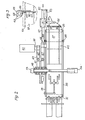
- the flat workpieces or sacks to be wound are fed in the form shown in FIG. 1 in a scale formation on a conveyor belt of the winding device. Since the scale spacing of the incoming workpieces may differ, a device for equalizing the scale spacing is provided so that a uniformly wound scale tape roll can be formed. This device has a pressure roller 25. On the opposite side, ie below the scale, there is a sensor 26 which scans the workpiece ends, the pulses of which are passed on to an electrical intermediate circuit 27.
- the scale After being scanned by the sensor 26, the scale is thrown onto an endless conveyor belt 28 which is formed from individual belts and runs over the rollers 29 to 34 which are rotatably mounted in a pivotable frame 35.
- the drive roller 36 is also attached to the frame 35, via which the strands are returned to the rollers 29.
- the frame 35 is pivotally mounted about the axis of the rollers 31 and is supported, for example, under the supply roller 37 to be wound by pneumatic cylinders 38, which have the task of tracking the frame 35 of the supply roller 37 in order to avoid out-of-roundness of the supply roller 37 which occurs during winding can compensate.
- a supply shaft 39 is provided on floor-mounted storage, from which retaining straps 40 are pulled, which are wound up in layers in a known manner with the workpieces on the supply roll 37.
- the axis of the drive roller 36 is equipped with a rotary pulse generator 41, the pulses of which are input to a counter 42.
- the counter 42 and the drive motor, not shown, of the drive roller 36 are with the Zwi circuit 27 electrically connected.
- the counter 42 can be set to a predetermined number and is switched so that the drive motor is stopped after reaching this number.
- the predetermined number is chosen somewhat larger than the intended scale band.
- the sensor 42 is reset to zero when a workpiece end passes by the sensor 26. If there is no workpiece, so that the counter 42 reaches the predetermined number, the conveyor belt 28 is stopped and it only starts to run again after the next workpiece has run through. Therefore, approximately the same scale distance is achieved on the conveyor belt 28.
- the core 45 of the supply roll 37 is held by a pin 46 which is fastened in the free end of a lever 47.
- the other end of the lever 47 is rotatably mounted on a bush 48 together with a second lever arm 49.
- the lever arm 49 carries a pin 50 corresponding to the pin 46 at its free end, but which extends in the opposite direction.
- Pressure medium cylinders 51, 52 are articulated to the lever arms 47 and 49, with which they or the supply roll 37 can be lowered onto the conveyor belt 28 and raised from there.
- the bushing 48 is smoothly and longitudinally displaceably mounted on an axis 53 which is fastened in a stand 54 arranged on both sides next to the conveyor belt 28.
- a guide part 55 is connected to the bushing 48 by a web 56.
- a roller 57 is loosely rotatably mounted on the guide part 55 and runs in a U-iron 58 which connects the two stands 54.
- the free ends of the pressure medium cylinders 51, 52 are articulated on the guide part 56.
- the bushing 48 can now be moved with the levers 47, 49, so that the pin 46 is above the conveyor belt 28 and the pin 50 is outside the winding area. While a new supply roll 37 is being wound on the pin 46, the finished supply roll can be removed from the pin 50 and a new core 45 can be prepared. After completion of the supply roll 37 on the pin 46, it is lifted off the conveyor belt 28 by means of the pressure medium cylinder 51 and the bush 48 is shifted into its other extreme position, and the supply roll 37 is lowered on the hall floor and pulled off the
- the pressure medium cylinders 51, 52 connecting the levers 47, 49 to the sled-shaped guide part 55 are hydraulic piston-cylinder units, while the conveyor belts running over the frame-shaped frame 35 pass through a pneumatic cylinder 38 to the winding core or the forming scale roll 37 can be pressed.
- the pneumatic cylinder 38 has a stroke of approximately 100 mm and is held in its central position by the fact that the hydraulic cylinders 51, 52 raise the levers 47, 49 in accordance with the winding progress.
- the hydraulic cylinders 51, 52 can be actuated in that the pneumatic cylinder is provided with a limit switch.
- the pneumatic cylinder 38 has good resilient properties, so that it is able to compensate for out-of-roundness of the scale roller 37 that is being formed.
- the retaining straps 40 are wound around the roller 37 for about two more turns.
- the press device 60 is then switched on and this holds the belts 40 in place when the roll is lifted off the press belts or the scale belt 33, 28.
- the wristbands are only fixed manually when the empty roll is in the take-up station.
- the pressing device 60 is mounted on an arm 61 which is firmly connected to the lever 47.
- a cross member 62 is fastened to the arm 61 and a pressure cylinder 63 is articulated to the free end thereof.
- the piston rod of the pressure cylinder 63 is articulated on a lever 64.
- One end of the lever 64 is articulated to a bracket 65.
- a cross member 66 is articulated in a rocker-like manner, to which pressure pieces 67 are articulated, which can press onto the holding tapes 50 wound around the supply roll 37 when the pressure cylinder 63 is actuated.
- the bracket 65 encompasses half of the arm 61. At the same height on the arm 61 there is a second bracket 68 which is symmetrical to the bracket 65 and which is connected to the bracket 65 by screws 69 and clamped together with it on the arm 61.
- a correspondingly designed second pressing device 60 is arranged on the arm 49. However, this is not shown in FIG. 2.
Landscapes
- Engineering & Computer Science (AREA)
- Mechanical Engineering (AREA)
- Replacement Of Web Rolls (AREA)
- Making Paper Articles (AREA)
Claims (9)
Applications Claiming Priority (4)
| Application Number | Priority Date | Filing Date | Title |
|---|---|---|---|
| DE3048721 | 1980-12-23 | ||
| DE3048721 | 1980-12-23 | ||
| DE3135575A DE3135575C2 (de) | 1980-12-23 | 1981-09-08 | Vorrichtung zum Herstellen von Schuppenbandrollen |
| DE3135575 | 1981-09-08 |
Publications (2)
| Publication Number | Publication Date |
|---|---|
| EP0054973A1 EP0054973A1 (fr) | 1982-06-30 |
| EP0054973B1 true EP0054973B1 (fr) | 1985-11-21 |
Family
ID=25789980
Family Applications (1)
| Application Number | Title | Priority Date | Filing Date |
|---|---|---|---|
| EP81110742A Expired EP0054973B1 (fr) | 1980-12-23 | 1981-12-23 | Dispositif de fabrication de rouleaux de bandes formées à partir de feuilles souples imbriqueés |
Country Status (3)
| Country | Link |
|---|---|
| EP (1) | EP0054973B1 (fr) |
| DE (1) | DE3135575C2 (fr) |
| ES (1) | ES508262A0 (fr) |
Cited By (1)
| Publication number | Priority date | Publication date | Assignee | Title |
|---|---|---|---|---|
| DE4221911A1 (de) * | 1992-07-03 | 1994-01-05 | Kolbus Gmbh & Co Kg | Verfahren zum Stapeln von Druckbogen und Vorrichtung zur Durchführung des Verfahrens |
Families Citing this family (2)
| Publication number | Priority date | Publication date | Assignee | Title |
|---|---|---|---|---|
| RU1804426C (ru) * | 1986-05-02 | 1993-03-23 | Фераг Аг | Устройство дл сматывани в переносной рулон каскадно подводимой печатной продукции и обв зывани полученного рулона |
| CH679993A5 (fr) * | 1987-03-06 | 1992-05-29 | Ferag Ag |
Family Cites Families (6)
| Publication number | Priority date | Publication date | Assignee | Title |
|---|---|---|---|---|
| FR857390A (fr) * | 1939-07-05 | 1940-09-09 | Rkoppwerke Ag Du | Dispositif pour monter et dérouler des balles d'étoffe |
| FR1604539A (fr) * | 1967-10-10 | 1971-11-29 | ||
| US3845915A (en) * | 1970-07-29 | 1974-11-05 | Kalle Ag | Winding machine |
| DE2349439A1 (de) * | 1973-10-02 | 1975-04-03 | Heinrich Schnell | Vorrichtung an schlingflorbobinenwicklern |
| DE2544135C2 (de) * | 1975-10-02 | 1982-11-25 | Windmöller & Hölscher, 4540 Lengerich | Vorrichtung zum Herstellen von Schuppenbandrollen aus geschuppt übereinander abgelegten flachen Werkstücken |
| CH617408A5 (fr) * | 1977-05-27 | 1980-05-30 | Ferag Ag |
-
1981
- 1981-09-08 DE DE3135575A patent/DE3135575C2/de not_active Expired
- 1981-12-22 ES ES508262A patent/ES508262A0/es active Granted
- 1981-12-23 EP EP81110742A patent/EP0054973B1/fr not_active Expired
Cited By (1)
| Publication number | Priority date | Publication date | Assignee | Title |
|---|---|---|---|---|
| DE4221911A1 (de) * | 1992-07-03 | 1994-01-05 | Kolbus Gmbh & Co Kg | Verfahren zum Stapeln von Druckbogen und Vorrichtung zur Durchführung des Verfahrens |
Also Published As
| Publication number | Publication date |
|---|---|
| EP0054973A1 (fr) | 1982-06-30 |
| ES8301175A1 (es) | 1982-12-01 |
| DE3135575A1 (de) | 1982-08-12 |
| ES508262A0 (es) | 1982-12-01 |
| DE3135575C2 (de) | 1985-09-12 |
Similar Documents
| Publication | Publication Date | Title |
|---|---|---|
| DE4401959C2 (de) | Tragtrommelroller für eine Papiermaschine | |
| DE69507490T2 (de) | Verfahren und vorrichtung zum aufwickeln einer laufenden bahn in eine bahnrolle | |
| EP0498962B1 (fr) | Procédé et dispositif pour réaliser une bobine | |
| DE3874212T2 (de) | Vorrichtung und verfahren zum wechseln einer folienrolle zur umhuellung. | |
| EP0054903B1 (fr) | Machine d'emballage pour des rouleaux à douille intérieure | |
| DE2658294C2 (de) | Vorrichtung zum Vereinzeln und Zuführen von mit Haltebändern in einer Schuppenbandrolle gespeicherten flachen Gegenständen zu nachfolgenden Stationen | |
| EP0054735B1 (fr) | Dispositif de fabrication de rouleaux de bandes formées à partir de feuilles souples imbriqueés | |
| EP0538566B1 (fr) | Machine pour enrouler des bandes de matière en bobines | |
| EP0135080B1 (fr) | Dispositif pour enrouler une pluralité de feuilles imprimées | |
| EP0054973B1 (fr) | Dispositif de fabrication de rouleaux de bandes formées à partir de feuilles souples imbriqueés | |
| DE3643026C2 (fr) | ||
| DE3914776A1 (de) | Verfahren und vorrichtung zum aufwickeln und querschneiden einer laufenden warenbahn | |
| DE4135101A1 (de) | Bahnzufuehrungsvorrichtung fuer papierrollenwechsel bei rotationsdruckmaschinen | |
| DE4039048C2 (de) | Wickelvorrichtung zum Aufwickeln einer kontinuierlich zugeführten Kunststoffbahn | |
| DE3838563A1 (de) | Vorrichtung zum stapeln von flachen gegenstaenden | |
| EP0232553A1 (fr) | Dispositif pour enrouler des objets plats arrivant en formation continue imbriqué | |
| EP0406581B1 (fr) | Dispositif pour couper une bande sur un rouleau d'inversement | |
| EP0514334B1 (fr) | Installation de compression d'une machine d'enveloppement pour fabriquer des paquets cylindriques d'articles d'imprimerie | |
| EP0093950A1 (fr) | Méthode et dispositif pour enrouler des feuilles continues | |
| DE2243504C2 (de) | Vorrichtung zum fortlaufenden Aufwickeln einer Folienbahn auf Wickelhülsen | |
| DE3139290A1 (de) | Vorrichtung zum herstellen von schuppenbandrollen aus geschuppt uebereinander abgelegten flachen flexiblen gegenstaenden | |
| DE2619954B2 (de) | Verfahren und Vorrichtung zur kontinuierlichen Behandlung einer band- oder drahtförmigen Materialbahn | |
| DE2203696A1 (de) | Mehrfach-wickelwendemaschine mit kontaktwalzensystem | |
| DE2249367C3 (de) | Vorrichtung zum kontinuierlichen Aufwickeln dünnen bahnförmigen Guts | |
| DE2519767B2 (de) | Herstellung und weiterverarbeitung von unwuchtausgleichsgewichten |
Legal Events
| Date | Code | Title | Description |
|---|---|---|---|
| PUAI | Public reference made under article 153(3) epc to a published international application that has entered the european phase |
Free format text: ORIGINAL CODE: 0009012 |
|
| AK | Designated contracting states |
Designated state(s): FR GB IT |
|
| 17P | Request for examination filed |
Effective date: 19821123 |
|
| ITF | It: translation for a ep patent filed | ||
| GRAA | (expected) grant |
Free format text: ORIGINAL CODE: 0009210 |
|
| AK | Designated contracting states |
Designated state(s): FR GB IT |
|
| ET | Fr: translation filed | ||
| PLBE | No opposition filed within time limit |
Free format text: ORIGINAL CODE: 0009261 |
|
| STAA | Information on the status of an ep patent application or granted ep patent |
Free format text: STATUS: NO OPPOSITION FILED WITHIN TIME LIMIT |
|
| 26N | No opposition filed | ||
| ITTA | It: last paid annual fee | ||
| PGFP | Annual fee paid to national office [announced via postgrant information from national office to epo] |
Ref country code: GB Payment date: 19971121 Year of fee payment: 17 |
|
| PGFP | Annual fee paid to national office [announced via postgrant information from national office to epo] |
Ref country code: FR Payment date: 19971215 Year of fee payment: 17 |
|
| PG25 | Lapsed in a contracting state [announced via postgrant information from national office to epo] |
Ref country code: GB Free format text: LAPSE BECAUSE OF NON-PAYMENT OF DUE FEES Effective date: 19981223 |
|
| GBPC | Gb: european patent ceased through non-payment of renewal fee |
Effective date: 19981223 |
|
| PG25 | Lapsed in a contracting state [announced via postgrant information from national office to epo] |
Ref country code: FR Free format text: LAPSE BECAUSE OF NON-PAYMENT OF DUE FEES Effective date: 19990831 |
|
| REG | Reference to a national code |
Ref country code: FR Ref legal event code: ST |