EP0054977A1 - Appareil de surveillance photographique pour voiture - Google Patents
Appareil de surveillance photographique pour voiture Download PDFInfo
- Publication number
- EP0054977A1 EP0054977A1 EP81110779A EP81110779A EP0054977A1 EP 0054977 A1 EP0054977 A1 EP 0054977A1 EP 81110779 A EP81110779 A EP 81110779A EP 81110779 A EP81110779 A EP 81110779A EP 0054977 A1 EP0054977 A1 EP 0054977A1
- Authority
- EP
- European Patent Office
- Prior art keywords
- housing
- photographic
- actuating element
- monitoring device
- camera
- Prior art date
- Legal status (The legal status is an assumption and is not a legal conclusion. Google has not performed a legal analysis and makes no representation as to the accuracy of the status listed.)
- Pending
Links
Images

Classifications
-
- G—PHYSICS
- G08—SIGNALLING
- G08B—SIGNALLING SYSTEMS, e.g. PERSONAL CALLING SYSTEMS; ORDER TELEGRAPHS; ALARM SYSTEMS
- G08B13/00—Burglar, theft or intruder alarms
- G08B13/18—Actuation by interference with heat, light, or radiation of shorter wavelength; Actuation by intruding sources of heat, light, or radiation of shorter wavelength
- G08B13/189—Actuation by interference with heat, light, or radiation of shorter wavelength; Actuation by intruding sources of heat, light, or radiation of shorter wavelength using passive radiation detection systems
- G08B13/194—Actuation by interference with heat, light, or radiation of shorter wavelength; Actuation by intruding sources of heat, light, or radiation of shorter wavelength using passive radiation detection systems using image scanning and comparing systems
- G08B13/196—Actuation by interference with heat, light, or radiation of shorter wavelength; Actuation by intruding sources of heat, light, or radiation of shorter wavelength using passive radiation detection systems using image scanning and comparing systems using television cameras
- G08B13/19665—Details related to the storage of video surveillance data
- G08B13/19669—Event triggers storage or change of storage policy
-
- G—PHYSICS
- G03—PHOTOGRAPHY; CINEMATOGRAPHY; ANALOGOUS TECHNIQUES USING WAVES OTHER THAN OPTICAL WAVES; ELECTROGRAPHY; HOLOGRAPHY
- G03B—APPARATUS OR ARRANGEMENTS FOR TAKING PHOTOGRAPHS OR FOR PROJECTING OR VIEWING THEM; APPARATUS OR ARRANGEMENTS EMPLOYING ANALOGOUS TECHNIQUES USING WAVES OTHER THAN OPTICAL WAVES; ACCESSORIES THEREFOR
- G03B29/00—Combinations of cameras, projectors or photographic printing apparatus with non-photographic non-optical apparatus, e.g. clocks or weapons; Cameras having the shape of other objects
-
- G—PHYSICS
- G08—SIGNALLING
- G08B—SIGNALLING SYSTEMS, e.g. PERSONAL CALLING SYSTEMS; ORDER TELEGRAPHS; ALARM SYSTEMS
- G08B13/00—Burglar, theft or intruder alarms
- G08B13/18—Actuation by interference with heat, light, or radiation of shorter wavelength; Actuation by intruding sources of heat, light, or radiation of shorter wavelength
- G08B13/189—Actuation by interference with heat, light, or radiation of shorter wavelength; Actuation by intruding sources of heat, light, or radiation of shorter wavelength using passive radiation detection systems
- G08B13/194—Actuation by interference with heat, light, or radiation of shorter wavelength; Actuation by intruding sources of heat, light, or radiation of shorter wavelength using passive radiation detection systems using image scanning and comparing systems
- G08B13/196—Actuation by interference with heat, light, or radiation of shorter wavelength; Actuation by intruding sources of heat, light, or radiation of shorter wavelength using passive radiation detection systems using image scanning and comparing systems using television cameras
- G08B13/19617—Surveillance camera constructional details
- G08B13/19619—Details of casing
-
- G—PHYSICS
- G08—SIGNALLING
- G08B—SIGNALLING SYSTEMS, e.g. PERSONAL CALLING SYSTEMS; ORDER TELEGRAPHS; ALARM SYSTEMS
- G08B13/00—Burglar, theft or intruder alarms
- G08B13/18—Actuation by interference with heat, light, or radiation of shorter wavelength; Actuation by intruding sources of heat, light, or radiation of shorter wavelength
- G08B13/189—Actuation by interference with heat, light, or radiation of shorter wavelength; Actuation by intruding sources of heat, light, or radiation of shorter wavelength using passive radiation detection systems
- G08B13/194—Actuation by interference with heat, light, or radiation of shorter wavelength; Actuation by intruding sources of heat, light, or radiation of shorter wavelength using passive radiation detection systems using image scanning and comparing systems
- G08B13/196—Actuation by interference with heat, light, or radiation of shorter wavelength; Actuation by intruding sources of heat, light, or radiation of shorter wavelength using passive radiation detection systems using image scanning and comparing systems using television cameras
- G08B13/19617—Surveillance camera constructional details
- G08B13/19626—Surveillance camera constructional details optical details, e.g. lenses, mirrors or multiple lenses
- G08B13/19628—Surveillance camera constructional details optical details, e.g. lenses, mirrors or multiple lenses of wide angled cameras and camera groups, e.g. omni-directional cameras, fish eye, single units having multiple cameras achieving a wide angle view
-
- G—PHYSICS
- G08—SIGNALLING
- G08B—SIGNALLING SYSTEMS, e.g. PERSONAL CALLING SYSTEMS; ORDER TELEGRAPHS; ALARM SYSTEMS
- G08B13/00—Burglar, theft or intruder alarms
- G08B13/18—Actuation by interference with heat, light, or radiation of shorter wavelength; Actuation by intruding sources of heat, light, or radiation of shorter wavelength
- G08B13/189—Actuation by interference with heat, light, or radiation of shorter wavelength; Actuation by intruding sources of heat, light, or radiation of shorter wavelength using passive radiation detection systems
- G08B13/194—Actuation by interference with heat, light, or radiation of shorter wavelength; Actuation by intruding sources of heat, light, or radiation of shorter wavelength using passive radiation detection systems using image scanning and comparing systems
- G08B13/196—Actuation by interference with heat, light, or radiation of shorter wavelength; Actuation by intruding sources of heat, light, or radiation of shorter wavelength using passive radiation detection systems using image scanning and comparing systems using television cameras
- G08B13/19639—Details of the system layout
- G08B13/19647—Systems specially adapted for intrusion detection in or around a vehicle
Definitions
- the invention relates to a photographic room monitoring device in passenger cars with a security device against external interference with a housing and with a photographic recording device. * and other rooms to be secured
- Such a photographic monitoring device is known from US Pat. No. 3,349,679.
- the known Raurrüberwdchungs shark contains a special camera, which is arranged in a lockable housing on the ceiling of a car.
- a flash device is also provided to illuminate the interior of the car.
- the monitoring device contains a control circuit for actuating the camera, which is switched on by opening and closing the car doors.
- the control circuit is prepared when the car door is opened and takes effect when it is closed. If necessary, a delay switch is effective, which triggers the camera and flashing light device after a predetermined time after the door has been closed.
- the invention has for its object to provide a photographic room monitoring device of the type mentioned, which is simple in construction, should be securely lockable and in which no externally accessible manipulations should be provided.
- the room monitoring device should be inexpensive to manufacture with little effort.
- the object is achieved in that the housing, which is fixed and two-part design, is at least partially translucent on the front, that camera mounting elements are provided within the housing and that at least one actuating element is contained in the housing, which in closed housing his working position has been transferred.
- This provides the advantage that the circuit for the camera motor can be closed in a simple manner with the aid of a switch provided outside the housing, as a result of which the motor circuit of the camera is closed and at least one picture is taken. Since the trigger is held in its actuated position by an actuating element when the housing is closed, advantageously no mechanical means to be actuated from the outside are necessary. With the photographic camera switched to series operation, any number of pictures can be taken, depending on the actuation time of the external switch.
- a wide-angle lens in particular a so-called “peephole” is arranged in the front of the housing. This "peephole” is aligned with the beam path of the lens of the motor camera used.
- the actuating element is provided in the upper housing part. This has the advantage that when the upper housing part is placed on the lower housing part, the actuating element is inevitably transferred to its working position and the camera trigger is brought into the working position.
- the actuating element is arranged movably, an actuating spring acting on the actuating element.
- the actuating spring is used to transfer the camera trigger into its working position, since the force of the actuating spring is at least equal to the triggering force of the camera trigger.
- a disk-like intermediate part is provided between the end face of the battery and the associated contact element, which is made up of an insulating medium part and two conductive coverings or layers arranged on both sides, each of the conductive coverings or layers a connecting line is led to the outside.
- a timer circuit preferably a monostable multivibrator with a time constant which can be preselected by means of a handle, can be provided within the housing, by means of which a relay can be influenced, by means of whose contact the electrical parts on the camera side can be energized and de-energized, from the input of the timer circuit , preferably via a plug-coupling connection leads to at least one two-wire line to an externally arranged signal button.
- an actuating element is provided, which is movably mounted in a housing-fixed holder, with a spring on the actuating element attacks, against the force of which the actuating element can be moved away and wherein the force of the spring has a minimum value.
- the actuating element has a control or ramp slope.
- the two housing parts have, in the region of their overlaps, recesses which are aligned with one another and each for receiving a mortise lock.
- the underside of the housing is advantageously provided with bores for receiving fastening elements.
- the front of the housing has a window area. This window area is adapted to the size of the built-in or attachable flash unit.
- the fastening element is a threaded part which is provided on a bracket of the camera holder.
- This bracket with fastening element also serves to fix the position of the camera in the holder.
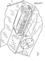
- FIGS. 1 to 5 The invention is described below with reference to an exemplary embodiment shown in FIGS. 1 to 5.
- a two-part plastic housing 1 and 2 is arranged in the interior of a passenger car directly behind the windshield 3.
- An approximately rectangular window area 4 is provided on the front side of the upper housing part 1, which is designed to be translucent.
- a so-called "door spy” 7 is provided as a wide-angle objective.
- an alarm button is designated.
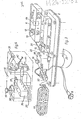
- FIG. 2 the parts corresponding to the parts according to FIG. 1 are provided with the same reference symbols.
- the photographic camera 6 is held by holders 9 and 10 provided on the lower housing part 2. 11 with an adjusting screw is referred to which is brought into its working position when the camera 6 is inserted into the holders 9 and 10 and in this case actuates the trigger designated with 12.
- an electric motor is provided within the photographic camera 6, through which the film can be transported on the one hand and through which on the other hand after each shot the shutter is tightened again.
- a series key is designated, which has two working positions. In the pressed position, single shots can be taken with the help of the photographic camera. With the series button 13 disengaged, it is in the second working position for continuous shooting.
- the series button 13 is transferred from its first working position into the second (disengaged working position) by simply pressing it.
- the series button is unlocked and can move into the disengaged position with the help of a spring acting on it.
- a compression spring 14 acts on the series button 13.
- the series button is connected to a locking element 15.
- a switch 16 is located below the membrane trigger 12.
- a flash lamp arrangement 17 is attached to the camera.
- 18 denotes a timer relay circuit, the time effect of which can be adjusted by means of a handle 19.
- An electrical line 24 leads from the alarm pressure switch 8 to the interior of the housing. Likewise, a line leads from the car battery 25 into the interior of the housing 1, 2.
- the upper housing part is provided on the opposite narrow sides with an opening 26 for a plug lock 27.
- An associated opening 28 is provided on the lower part of the housing at the corresponding points. This has a backward rotation 29 in order to enable a secure locking of the plug lock 27. Designated by 30 the assigned socket wrench.
- FIG. 3 the parts corresponding to the parts according to FIGS. 1 and 2 are provided with the same reference symbols.
- a connector 31, 32 is provided on the lower housing part 2, which connects the alarm switch 8 and the battery 25 to the so-called timer trigger circuit 18.
- This timer circuit 18 has a connection socket 33 for a plug 34, from which a line 35 leads to the camera 6.
- the timer circuit 18 consists of a monostable multivibrator 36, the time-determining element of which has a capacitor 37 and a variable resistor 38.
- the resistor 38 can be changed with the help of the rotary handle 19.
- the control input of the multivibrator 36, designated 39, can be connected to the alarm switch 8. From the output of the multivibrator, two lines lead to the coil 40 of a relay, the armature 41 of which is under the action of a spring 42 and by means of which a switch 43 can be actuated. With the help of the switch 43, the negative pole of the battery 25 can be connected to a connection of the plug socket 33. The other connection of the plug socket 33 is connected directly to the positive pole of the battery 25.
- the monostable multivibrator 36 Upon actuation of the alarm button, the monostable multivibrator 36 8.er proceedings a control pulse, which causes the energization of the relay 40 and thus the ⁇ closure of the switch 43.
- the relay 40 During a predetermined time period that is dependent remains on the position of the rotary knob 19 the relay 40 is energized, and so that the switch 43 is closed.
- the motor not shown, is energized in the camera 6 and causes a predetermined number of pictures to be taken.
- an actuating screw denoted by 44 is like this screwed far down that the camera trigger 12 is in the pressed position.
- the shutter of the camera can be actuated as often as required simply by actuating the alarm button 8 with the aid of the built-in motor, without the need for mechanical actuation means which are guided to the outside.
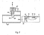
- an actuating device according to FIG. 5 which has the particular advantage that the series button 13 and the trigger 12 are automatically actuated when the camera is inserted or inserted into the brackets 9 and 10.
- the holder designated 10 ' has a bow-like attachment 45 in which an actuating element 46 is movably mounted.
- This actuating pin 46 is under the action of a spring 47 whose ⁇ force is greater than the force of the spring 14 of the series button 13 and greater than the actuating force of the trigger 12.
- This actuating pin 46 has a control slope 48 which is inclined so that the Pin 46 can be moved effortlessly in the direction of the arrow B when the camera is inserted in the direction of the arrow A into the holder 10 '.
- the actuating pin 46 has a rounded actuating area 49 adjacent to the control bevels 48.
- the actuating pin 46 When the camera 6 is inserted into the holder 10 ', the actuating pin 46 is moved in the direction of arrow B through the front edge of the camera via the control bevels 48. When pushed in further, the head 49 of the actuating pin 46 comes into operative connection with the series key 13 and presses it in the direction of arrow C. Here, the series key 13 is unlocked or uncoupled via the part 15. When the camera is pushed in further, the operative connection between the actuating pin 46 and serial button 13 is released, so that the se under the action of their spring 14 moves against the arrow direction C in the working position for continuous shooting.
Landscapes
- Physics & Mathematics (AREA)
- General Physics & Mathematics (AREA)
- Engineering & Computer Science (AREA)
- Multimedia (AREA)
- Studio Devices (AREA)
- Fittings On The Vehicle Exterior For Carrying Loads, And Devices For Holding Or Mounting Articles (AREA)
- Cameras Adapted For Combination With Other Photographic Or Optical Apparatuses (AREA)
Applications Claiming Priority (2)
| Application Number | Priority Date | Filing Date | Title |
|---|---|---|---|
| DE8033306U | 1980-12-15 | ||
| DE8033306 | 1980-12-15 |
Publications (1)
| Publication Number | Publication Date |
|---|---|
| EP0054977A1 true EP0054977A1 (fr) | 1982-06-30 |
Family
ID=6721414
Family Applications (2)
| Application Number | Title | Priority Date | Filing Date |
|---|---|---|---|
| EP81110779A Pending EP0054977A1 (fr) | 1980-12-15 | 1981-12-05 | Appareil de surveillance photographique pour voiture |
| EP82900098A Expired EP0066599B1 (fr) | 1980-12-15 | 1981-12-05 | Dispositif photographique pour la surveillance de l'interieur d'un vehicule automobile |
Family Applications After (1)
| Application Number | Title | Priority Date | Filing Date |
|---|---|---|---|
| EP82900098A Expired EP0066599B1 (fr) | 1980-12-15 | 1981-12-05 | Dispositif photographique pour la surveillance de l'interieur d'un vehicule automobile |
Country Status (4)
| Country | Link |
|---|---|
| EP (2) | EP0054977A1 (fr) |
| DE (1) | DE3166877D1 (fr) |
| ES (1) | ES262021Y (fr) |
| WO (1) | WO1982002099A1 (fr) |
Cited By (1)
| Publication number | Priority date | Publication date | Assignee | Title |
|---|---|---|---|---|
| GB2224358A (en) * | 1988-10-31 | 1990-05-02 | Michael Jefferson Lawrence | "vehicle security camera" |
Families Citing this family (1)
| Publication number | Priority date | Publication date | Assignee | Title |
|---|---|---|---|---|
| US4855770A (en) * | 1988-09-09 | 1989-08-08 | Polaroid Corporation | Vehicle identification camera |
Family Cites Families (3)
| Publication number | Priority date | Publication date | Assignee | Title |
|---|---|---|---|---|
| DE1167575B (de) * | 1957-10-22 | 1964-04-09 | Robot Berning & Co | Photographische Raumueberwachungsvorrichtung |
| US3349679A (en) * | 1965-04-07 | 1967-10-31 | Iii Joseph A Lohman | Photo identification apparatus |
| US3752047A (en) * | 1971-12-13 | 1973-08-14 | L Gordon | Surveillance camera |
-
1981
- 1981-12-05 EP EP81110779A patent/EP0054977A1/fr active Pending
- 1981-12-05 EP EP82900098A patent/EP0066599B1/fr not_active Expired
- 1981-12-05 WO PCT/EP1981/000190 patent/WO1982002099A1/fr not_active Ceased
- 1981-12-05 DE DE8282900098T patent/DE3166877D1/de not_active Expired
- 1981-12-14 ES ES1981262021U patent/ES262021Y/es not_active Expired
Cited By (2)
| Publication number | Priority date | Publication date | Assignee | Title |
|---|---|---|---|---|
| GB2224358A (en) * | 1988-10-31 | 1990-05-02 | Michael Jefferson Lawrence | "vehicle security camera" |
| GB2224358B (en) * | 1988-10-31 | 1992-02-26 | Michael Jefferson Lawrence | Vehicle security camera |
Also Published As
| Publication number | Publication date |
|---|---|
| WO1982002099A1 (fr) | 1982-06-24 |
| EP0066599A1 (fr) | 1982-12-15 |
| ES262021U (es) | 1982-07-16 |
| DE3166877D1 (en) | 1984-11-29 |
| ES262021Y (es) | 1983-02-01 |
| EP0066599B1 (fr) | 1984-10-24 |
Similar Documents
| Publication | Publication Date | Title |
|---|---|---|
| DE2812952B2 (de) | Photoelektrischer Schalter | |
| DE3425108C1 (de) | Verriegelungsvorrichtung fuer Schloesser der Hintertueren eines Kraftfahrzeuges | |
| EP0878600B1 (fr) | Dispositif d'ouverture basculante pour portes ou fenêtres actionné par un moteur électrique | |
| DE3501345C2 (de) | Profilzylinder | |
| DE2223662A1 (de) | Alarmvorrichtung gegen Einbruch und Diebstahl | |
| DE2630331A1 (de) | Vorrichtung zur diebstahlsicherung elektrisch betriebener geraete, insbesondere in kraftfahrzeugen | |
| EP0066599B1 (fr) | Dispositif photographique pour la surveillance de l'interieur d'un vehicule automobile | |
| DE69819436T2 (de) | Multifunktioneller Verschlussauslöser | |
| EP1400936B2 (fr) | Dispositif de surveillance et de sécurité pour portes, fenêtres et similaires | |
| DE3826108C2 (fr) | ||
| DE2946281A1 (de) | Elektronisches messgeraet in modul- bauweise | |
| DE3047201A1 (de) | Fotografische raumueberwachungseinrichtung | |
| DE8033306U1 (de) | Fotografische Raumüberwachungseinrichtung | |
| DE2841648B2 (de) | Betätigungshandhabe für eine fotografische Kamera mit einer mittels der Handhabe betätigbaren Einstellvorrichtung | |
| DE4207128C2 (de) | Kontaktvorrichtung zur elektrischen Überwachung von Eingangstüren | |
| DE2836974C2 (de) | Innenleuchte | |
| DE2948720C2 (fr) | ||
| EP0621617A1 (fr) | Disjoncteur à dispositif additionel | |
| DE4241543A1 (en) | Adjustment device for motor vehicle's rear=view mirrors - has remotely controlled drive for tilting each reflector rapidly and precisely between operative and dipped positions | |
| DE3740025C2 (fr) | ||
| DE2909895C2 (de) | Aus Funktionsgruppen zusammengesetzte Fernsehkamera | |
| DE1809389C3 (de) | Kinematographische Kamera | |
| DE29517876U1 (de) | Überwachungsgerät mit einem Gehäuse und Anschlußklemmen | |
| DE8413850U1 (de) | Einbau-Zeitschaltuhr | |
| DE19624217C2 (de) | Saugsteckdose, insbesondere für Zentralstaubsauganlagen |
Legal Events
| Date | Code | Title | Description |
|---|---|---|---|
| PUAI | Public reference made under article 153(3) epc to a published international application that has entered the european phase |
Free format text: ORIGINAL CODE: 0009012 |
|
| AK | Designated contracting states |
Designated state(s): IT |
|
| STAA | Information on the status of an ep patent application or granted ep patent |
Free format text: STATUS: REQUEST FOR EXAMINATION WAS MADE |
|
| 17P | Request for examination filed |
Effective date: 19820716 |
|
| XX | Miscellaneous (additional remarks) |
Free format text: VERFAHREN ABGESCHLOSSEN INFOLGE VERBINDUNG MIT 82900098.3/66599 (EUROPAEISCHE ANMELDENUMMER/VEROEFFENTLICHUNGSNUMMER) VOM 23.02.83. |
|
| ITF | It: translation for a ep patent filed | ||
| RIN1 | Information on inventor provided before grant (corrected) |
Inventor name: MOSKOVITS, FRANCISC |