EP0054985A1 - Dispositif pour armer manuellement une arme à feu automatique - Google Patents
Dispositif pour armer manuellement une arme à feu automatique Download PDFInfo
- Publication number
- EP0054985A1 EP0054985A1 EP81201227A EP81201227A EP0054985A1 EP 0054985 A1 EP0054985 A1 EP 0054985A1 EP 81201227 A EP81201227 A EP 81201227A EP 81201227 A EP81201227 A EP 81201227A EP 0054985 A1 EP0054985 A1 EP 0054985A1
- Authority
- EP
- European Patent Office
- Prior art keywords
- locking
- drive shaft
- housing
- locking bolt
- holder
- Prior art date
- Legal status (The legal status is an assumption and is not a legal conclusion. Google has not performed a legal analysis and makes no representation as to the accuracy of the status listed.)
- Granted
Links
- 230000000903 blocking effect Effects 0.000 claims description 2
- 208000027418 Wounds and injury Diseases 0.000 abstract description 2
- 230000006378 damage Effects 0.000 abstract description 2
- 208000014674 injury Diseases 0.000 abstract description 2
- 230000002028 premature Effects 0.000 abstract description 2
- 238000006073 displacement reaction Methods 0.000 description 1
- 230000002349 favourable effect Effects 0.000 description 1
- 238000010304 firing Methods 0.000 description 1
- 230000002787 reinforcement Effects 0.000 description 1
Images

Classifications
-
- F—MECHANICAL ENGINEERING; LIGHTING; HEATING; WEAPONS; BLASTING
- F41—WEAPONS
- F41A—FUNCTIONAL FEATURES OR DETAILS COMMON TO BOTH SMALLARMS AND ORDNANCE, e.g. CANNONS; MOUNTINGS FOR SMALLARMS OR ORDNANCE
- F41A7/00—Auxiliary mechanisms for bringing the breech-block or bolt or the barrel to the starting position before automatic firing; Drives for externally-powered guns; Remote-controlled gun chargers
- F41A7/02—Machine gun rechargers, e.g. manually operated
Definitions
- the invention relates to a manual tensioning device for an automatic firearm, with a driver which can be moved via a tensioning chain for retrieving a breech against the force of its retraction means, with a chain wheel which is in engagement with the tensioning chain and which is operatively connected to a drive shaft which can be driven via a removable crank handle.
- a closure tensioning device of this type is known from CH-PS 459 000. This device has the disadvantage that if the hand crank is released prematurely before the lock is caught by the trigger in its rearmost position, the lock is prematurely accelerated forward and the shooter is endangered, not least because of the rapidly rotating hand crank.
- the invention solves the problem of creating an easy-to-use manual clamping device in which the risk of premature closure advance is eliminated.
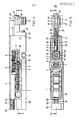
- a manual tensioning device attached to an automatic firearm in a manner not shown in detail on an automatic firearm has an endless tensioning chain 1 which is in engagement with two chain wheels 2, 3. 3, the front sprocket 2 is rotatably mounted in a front deflection housing 5 via a shaft 4.
- the rear sprocket 3 is arranged on a square shaft 7 rotatably mounted in a housing 6.
- a gear 8 is also rotatably mounted, which is in engagement with a drive shaft 10 assigned drive wheel 9.
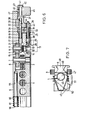
- the drive shaft 10 rotatably mounted in the housing 6 has two square parts 11, 12. On one square part 11, a ratchet wheel 15 is placed next to the drive wheel 9 and positioned via a pin 16.
- the shape of the ratchet wheel 15 can be seen particularly in FIG. 5.
- the ratchet wheel 15 is provided with teeth 15a with tooth flanks 15b, 15c of different steepness.
- the other rectangular portion 12 of the drive shaft 10 is designed for a hand crank 13 which is shown schematically in phantom in Fg. 6 and via which the drive of the hand tensioning device.
- crank handle 13 is associated with a safety cam 25, which can be seen in FIG.
- the crank handle 13 is axially secured on the square part 12 via a nose 26 of the securing bolt 25 and a flange 14 of the crank handle 13.
- the ratchet wheel 15 is assigned a ratchet pin 17 which is perpendicular to the drive shaft 10, i.e. parallel to the locking pin 25 in the housing 6 is mounted for longitudinal displacement (FIGS. 5 and 6).
- a part 18 of the locking bolt 17 with a reduced diameter projects through a bore 34 in a housing part 33 which can be removed from the housing 6 and into a blind bore 38 in a holder 37.
- a spring 19 is arranged around this part 18 of the locking bolt 17 and is supported on the one hand on a shoulder 20 of the locking bolt 17 and on the other hand on the housing part 33.
- the locking pin 17 also has a nose 21 which engages with the toothing 15a of the locking wheel 15 according to FIG.
- Ratchet wheels are able to cause a short lifting of the locking bolt 17 against the force of the spring 19.
- the stroke of the locking pin 17 is limited by a recess or a slot 22 in the same and a cross pin 39 fastened in the holder 37.
- the holder 37 has a cylindrical extension 40 which is provided with two parallel surfaces 41 and which is closed off by a head 42.
- a handle 45 is provided with a slot 46 offset by 90 ° with respect to the surfaces 41, the position of the slot 46 preventing the handle 45 from falling out in the assembled position.
- two flat recesses 28 are laterally made in a part 27 of the securing bolt 25 with a diameter, in which a fork-shaped part 43 of the holder 37 engages.
- the part 27 of the securing bolt 25 is surrounded by a spring 29 which is supported on the one hand on a shoulder 30 of the securing bolt 25 and on the other hand on the housing part 33.
- the part 27 is guided in a longitudinally displaceable manner through a bore 35 in the housing part 33.
- the holder 37 In the first position shown in FIGS. 4 to 6, the holder 37 is supported on the housing 6, more precisely on the housing part 33, via its front end face 44.
- the locking bolt 17, which is in axial connection with the holder 37, and also the locking bolt 25 are in engagement with the locking wheel 15 or with the hand crank 13.
- the holder 37 can be adjusted into a second position via the handle 45, the locking bolt 17 are brought against the force of the springs 19 and 29 via the cross pin 39 and the slot 22 and the securing bolt 25 via the fork-shaped part 43 of the holder 37 and the reinforcements 28 from the engagement with the ratchet wheel 15 or the hand crank 13.
- the holder 37 with the locking and securing bolt 17 or 25 In the second, rear position, the holder 37 with the locking and securing bolt 17 or 25 can be pivoted by a dash-dotted line in FIGS. 5 and 7 of the handle 45 are locked.
- An end face 47 (FIGS. 6 and 7) made on the handle 45 is pushed behind a rear face 48 of the housing 6 and the handle 45 is supported on an inclined surface 49 of the housing 6.
- a rod 56 is inserted, on which a driver 57 connected to the tension chain 1 is guided in a longitudinally displaceable manner.
- the driver 57 shown in FIGS. 1 and 3, with its nose 58 (FIGS. 1 and 2), is operatively connected to the closure, not shown, in a manner known per se and therefore not explained in detail.
- a forward spring 61 of the driver 57 arranged around the rod 56 is supported.
- An impact ring 53 is mounted on the rod 56 between the driver 57 and the front deflection housing 5. By inserting further impact rings, the starting position can be restored if the tension chain 1 is later stretched.
- the connection of the driver 57 to the tension chain 1 takes place via a tab 63 shown in FIGS. 2 and 3, which is connected to the driver 57 via a pin 62 and fastened to the two chain links 64, 65 (FIG. 2) of the tension chain 1 are.
- a side cover 50 is guided on the deflection housing 5 and fastened to the housing 6, the lower part 51 of which is arranged below the tension chain 1, as can be seen particularly from FIG. 7.
- a locking lever 67 which can be pivoted about an axis 66 and is loaded by a spring 69 and which engages with its nose 68 in a recess 70 of the driver 57.
- the driver 57 is also provided with a catch nose 71 which is brought forward to the recess 70 or closes it off at the front.
- the weapon breech Before firing, the weapon breech must be brought into its rear position using the hand-held clamping device shown and the forward spring of the weapon breech must be tensioned.
- the drive shaft 10 is rotated clockwise according to FIG. 5 via the hand crank 13, the locking bolt 17 being gradually raised against the force of the spring 19 by the less steep tooth flanks 15c of the locking wheel 15 rotating with the drive shaft 10 and the teeth of the Locking wheel 15 slide under the nose 21 of the locking pin 17.
- the holder 37 with the handle 45 is in the first position shown in FIGS. 4 to 6.
- the crank handle 13 is secured against falling out, since the nose 26 of the securing bolt 25 is located in front of the flange 14 of the crank handle 13 (FIG. 6).
- the gear 8 Via the drive wheel 9 assigned to the drive shaft 9, the gear 8 is driven with a favorable gear ratio and, via the square shaft 7, the rear sprocket 3 is also driven counterclockwise according to FIG. 5 and the tension chain 1 is set in motion.
- the driver 57 is pulled backwards via the chain links 64, 65 and the link plate 63 (FIG. 2).
- the catch nose 71 of the driver 57 presses the nose 68 of the in FIG. 3 at the beginning of this movement shown locking lever 67 out of the recess 70 and the locking lever 67 is pivoted against the force of the spring 69 the driver 57 out of the way.
- the weapon breech not shown, or its forward spring, are taken back or tensioned over the nose 58 of the catch 57, the forces of the forward spring 61 and the forward spring of the breech having to be overcome.
- the locking bolt 17 ensures that the forward spring 61, but above all the forward spring of the closure, is not able to move the catch 57 with the closure back into the forward position, even if the hand crank 13 should be let go for some reason.
- the nose 21 of the locking pin 71 blocks the ratchet wheel 15 in the reverse direction of the drive direction of rotation via the steeper tooth flank 15b. This prevents the breech from advancing prematurely, which would pose a great danger to the shooter.
- the driver 57 When the closure reaches its rearmost position, in which it is caught by a trigger pawl in a manner known per se and not shown in detail, the driver 57, which has thus fulfilled its function, can be returned to its front position.
- the blocking of the ratchet wheel 15 by the locking pin 17 is released in the direction of rotation reversed in the direction of rotation of the drive and the driver 57 by the forward spring 61 is pushed forward.
- the forward spring of the closure remains tensioned due to the locking of the closure on the trigger and does not participate in the forward movement of the driver 57.
- crank handle 13 is not also accelerated and rotated, which would pose a risk of injury to the shooter and would also unnecessarily increase the inertia of the mass to be accelerated, at the same time the pulling away of the locking pin 17 from the ratchet wheel 15, the locking pin 25 is pushed away from the hand crank 13 via the holder 37, and the hand crank 13 is removed.
- the driver 57 is in turn caught in the front position by the locking lever 67 acting as a rebound lock.
- the driver 57 can also be slowly moved forward with the lock (not shown) via the hand crank 13 in an emergency, e.g. to fix certain faults.
Landscapes
- Engineering & Computer Science (AREA)
- General Engineering & Computer Science (AREA)
- Devices For Conveying Motion By Means Of Endless Flexible Members (AREA)
Applications Claiming Priority (2)
| Application Number | Priority Date | Filing Date | Title |
|---|---|---|---|
| CH934180 | 1980-12-18 | ||
| CH9341/80 | 1980-12-18 |
Publications (2)
| Publication Number | Publication Date |
|---|---|
| EP0054985A1 true EP0054985A1 (fr) | 1982-06-30 |
| EP0054985B1 EP0054985B1 (fr) | 1984-09-05 |
Family
ID=4350954
Family Applications (1)
| Application Number | Title | Priority Date | Filing Date |
|---|---|---|---|
| EP81201227A Expired EP0054985B1 (fr) | 1980-12-18 | 1981-10-30 | Dispositif pour armer manuellement une arme à feu automatique |
Country Status (3)
| Country | Link |
|---|---|
| US (1) | US4421006A (fr) |
| EP (1) | EP0054985B1 (fr) |
| DE (1) | DE3165865D1 (fr) |
Cited By (1)
| Publication number | Priority date | Publication date | Assignee | Title |
|---|---|---|---|---|
| GB2248915A (en) * | 1982-05-08 | 1992-04-22 | Heckler & Koch Gmbh | Self-loading hand weapon |
Families Citing this family (2)
| Publication number | Priority date | Publication date | Assignee | Title |
|---|---|---|---|---|
| DE102010052536B3 (de) * | 2010-11-25 | 2012-03-08 | Blaser Finanzholding Gmbh | Kammer für ein Repetiergewehr |
| US9188400B2 (en) * | 2014-03-24 | 2015-11-17 | The United States Of America As Represented By The Secretary Of The Navy | System and method for charging a weapon |
Citations (4)
| Publication number | Priority date | Publication date | Assignee | Title |
|---|---|---|---|---|
| DE721590C (de) * | 1934-08-16 | 1942-06-10 | Rheinmetall Borsig Ag | Hebelspannvorrichtung fuer selbsttaetige Feuerwaffen |
| DE954824C (de) * | 1952-04-20 | 1956-12-20 | Winden U Maschb Josef Gressbac | Sicherheitsklinkengesperre fuer Winden mit mehreren Achsen |
| GB963119A (en) * | 1961-06-02 | 1964-07-08 | Brevets Aero Mecaniques | Improvements in automatic firearms with recoiling barrel, and in particular in heavy achine guns |
| CH459000A (de) * | 1965-09-29 | 1968-06-30 | Stoner Eugen Morrison | Automatisches Geschütz |
Family Cites Families (5)
| Publication number | Priority date | Publication date | Assignee | Title |
|---|---|---|---|---|
| DE289053C (fr) * | ||||
| US2408110A (en) * | 1944-07-10 | 1946-09-24 | United Shoe Machinery Corp | Gun-charging mechanism |
| US2845001A (en) * | 1955-11-30 | 1958-07-29 | Robert L Hillberg | Manual charger for a firearm |
| US3386336A (en) * | 1966-03-30 | 1968-06-04 | Colt S Inc | Convertible machine gun for rightand left-hand cartridge feed and operation |
| GB1255924A (en) * | 1966-11-29 | 1971-12-01 | Secr Defence | Improvements in or relating to cocking mechanisms for guns |
-
1981
- 1981-10-30 DE DE8181201227T patent/DE3165865D1/de not_active Expired
- 1981-10-30 EP EP81201227A patent/EP0054985B1/fr not_active Expired
- 1981-11-30 US US06/325,906 patent/US4421006A/en not_active Expired - Fee Related
Patent Citations (4)
| Publication number | Priority date | Publication date | Assignee | Title |
|---|---|---|---|---|
| DE721590C (de) * | 1934-08-16 | 1942-06-10 | Rheinmetall Borsig Ag | Hebelspannvorrichtung fuer selbsttaetige Feuerwaffen |
| DE954824C (de) * | 1952-04-20 | 1956-12-20 | Winden U Maschb Josef Gressbac | Sicherheitsklinkengesperre fuer Winden mit mehreren Achsen |
| GB963119A (en) * | 1961-06-02 | 1964-07-08 | Brevets Aero Mecaniques | Improvements in automatic firearms with recoiling barrel, and in particular in heavy achine guns |
| CH459000A (de) * | 1965-09-29 | 1968-06-30 | Stoner Eugen Morrison | Automatisches Geschütz |
Cited By (2)
| Publication number | Priority date | Publication date | Assignee | Title |
|---|---|---|---|---|
| GB2248915A (en) * | 1982-05-08 | 1992-04-22 | Heckler & Koch Gmbh | Self-loading hand weapon |
| GB2248915B (en) * | 1982-05-08 | 1992-09-16 | Heckler & Koch Gmbh | Self-loading hand weapon |
Also Published As
| Publication number | Publication date |
|---|---|
| DE3165865D1 (en) | 1984-10-11 |
| EP0054985B1 (fr) | 1984-09-05 |
| US4421006A (en) | 1983-12-20 |
Similar Documents
| Publication | Publication Date | Title |
|---|---|---|
| DE1453913C3 (de) | Abzugsvorrichtung für automatische Feuerwaffen | |
| DE2133551A1 (de) | Sicherungsvorrichtung fur den Schlag bolzen von Handfeuerwaffen | |
| EP0065101B1 (fr) | Limiteur de rafale pour armes à feu automatiques à percussion par chien | |
| DE2754761C2 (de) | "Abzugsvorrichtung für eine halbautomatische Schußwaffe" | |
| DE2757663A1 (de) | Doppel-sternradgurtzufuehrer fuer eine automatische feuerwaffe | |
| DE886706C (de) | Automatische Feuerwaffe | |
| EP0054985B1 (fr) | Dispositif pour armer manuellement une arme à feu automatique | |
| DE2332273C3 (de) | Fangvorrichtung für selbsttätige Feuerwaffe | |
| DE2362464A1 (de) | Schlagbolzensicherungseinrichtung fuer handfeuerwaffen | |
| EP0272247B1 (fr) | Arme à feu | |
| DE68909032T2 (de) | Automatische Sicherheitsvorrichtung für Feuerwaffen. | |
| DE2044920A1 (de) | Bolzensetzgerät mit Kartuschenmagazin | |
| DE607587C (de) | Feuerwaffe mit auswechselbarem Lauf | |
| DE69513449T2 (de) | Abfeuerungsvorrichtung für Geschütz durch den Schlag eines Zünders und Geschütz mit einer solcher Vorrichtung | |
| DE2365902B2 (de) | Selbsttaetige feuerwaffe | |
| DE957648C (de) | Zahnradgetriebe für Schaftmaschinen und Schützenwechselvorrichtungen an Webstühlen | |
| DE1453926C (de) | Zuführeinrichtung fur eine automatische Feuerwaffe, in die wahlweise ein Magazin und eine Gurtfuhrung einsetzbar sind | |
| DE1803814C3 (de) | Abzugsvorrichtung für eine mehrläufige Kippiaufwaffe mit Einabzug | |
| DE614813C (de) | Zuenderstellmaschine | |
| DE2621860C2 (de) | Verschlußmechanismus für eine Kamera | |
| DE210629C (fr) | ||
| DE11201C (de) | Neuerungen an Hinteriadungs- und Magazin-Feuerwaffen | |
| AT26847B (de) | Mehrladegewehr mit Trommelmagazin. | |
| DE174158C (fr) | ||
| DE557078C (de) | Leichtes Maschinengewehr mit gleitendem Lauf |
Legal Events
| Date | Code | Title | Description |
|---|---|---|---|
| PUAI | Public reference made under article 153(3) epc to a published international application that has entered the european phase |
Free format text: ORIGINAL CODE: 0009012 |
|
| AK | Designated contracting states |
Designated state(s): CH DE FR IT SE |
|
| 17P | Request for examination filed |
Effective date: 19820914 |
|
| ITF | It: translation for a ep patent filed | ||
| GRAA | (expected) grant |
Free format text: ORIGINAL CODE: 0009210 |
|
| AK | Designated contracting states |
Designated state(s): CH DE FR IT LI SE |
|
| REF | Corresponds to: |
Ref document number: 3165865 Country of ref document: DE Date of ref document: 19841011 |
|
| ET | Fr: translation filed | ||
| PLBE | No opposition filed within time limit |
Free format text: ORIGINAL CODE: 0009261 |
|
| STAA | Information on the status of an ep patent application or granted ep patent |
Free format text: STATUS: NO OPPOSITION FILED WITHIN TIME LIMIT |
|
| 26N | No opposition filed | ||
| PGFP | Annual fee paid to national office [announced via postgrant information from national office to epo] |
Ref country code: FR Payment date: 19911007 Year of fee payment: 11 |
|
| PGFP | Annual fee paid to national office [announced via postgrant information from national office to epo] |
Ref country code: SE Payment date: 19911014 Year of fee payment: 11 |
|
| PGFP | Annual fee paid to national office [announced via postgrant information from national office to epo] |
Ref country code: CH Payment date: 19911015 Year of fee payment: 11 |
|
| PGFP | Annual fee paid to national office [announced via postgrant information from national office to epo] |
Ref country code: DE Payment date: 19911021 Year of fee payment: 11 |
|
| ITTA | It: last paid annual fee | ||
| PG25 | Lapsed in a contracting state [announced via postgrant information from national office to epo] |
Ref country code: SE Effective date: 19921031 Ref country code: LI Effective date: 19921031 Ref country code: CH Effective date: 19921031 |
|
| PG25 | Lapsed in a contracting state [announced via postgrant information from national office to epo] |
Ref country code: FR Effective date: 19930630 |
|
| REG | Reference to a national code |
Ref country code: CH Ref legal event code: PL |
|
| PG25 | Lapsed in a contracting state [announced via postgrant information from national office to epo] |
Ref country code: DE Effective date: 19930701 |
|
| REG | Reference to a national code |
Ref country code: FR Ref legal event code: ST |
|
| EUG | Se: european patent has lapsed |
Ref document number: 81201227.6 Effective date: 19930510 |